

Page 1
DATA SHEET
DATE: April, 1939
No. 185
SUBJECT:
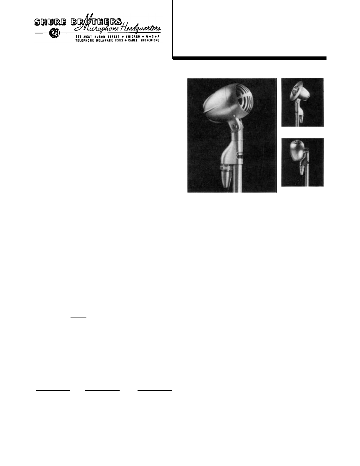
50 Series "Rocket" Dynamic Microphones
GENERAL:
tional pickup characteristics. The three models differ
only in output impedance as described under "Connections" below.
The microphones operate on the principle of a moving-conductor in a magnetic field. A high flux magnet
is used in the magnetic circuit, which together with a
specially designed moving system and associated acoustic network, provides high efficiency and smooth peak
free response.
The case is attractively streamlined for improved
acoustical performance and for modern appearance. Each
microphone is provided with a built-in receptacle and
shielded rubber jacketed cable with microphone plug
attached.
APPLICATIONS:
ment, and similar applications. Extreme ruggedness and
immunity to severe temperature and humidity conditions
are inherent in the design. The frequency response
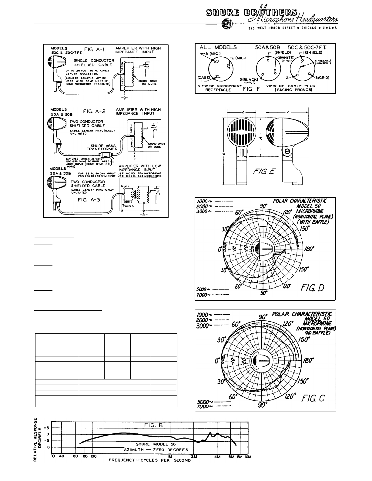
characteristic is wide range (see Fig. B) providing
high quality reproduction of sound from 70 to 7,000
cycles. The pickup characteristic is of the conventional semi-directional type. (See "Acoustic Consider-
ations"). A swivel is provided which permits pointing
the microphone toward the source of sound. A removable
directional baffle (Model A91A) is available for the
705A which increases discrimination against high-frequency sounds coming from the rear. When turned to the
vertical position (without baffle) the microphone becomes non-directional in the horizontal plane and
artists may be placed all around it without frequency
discrimination.
INSTALLATION: All microphones have thestandard 5/8"-27
floor stands are especially recommended because of the
effective isolation against floor vibration which they
provide. For overhead suspension, an A35B Suspension
Adapter may be used.
CONNECTIONS:
transformer with high permeability core. The output
impedances and cables furnished with the three models
are listed below:
Model
50A
50B
50C
50C-7FT high impedance
Low impedance models 50A and 50B are recommended
where long cable lengths are required. The permissible
line length is practically unlimited since neither the
level nor the frequency response is appreciably affected by reasonable lengths of line. As shown in the table
below the cable loss is very small. When long lines
are used,
parallel A.C. power lines for long distances to avoid
A.C. hum induction.
Cable Length Loss in Level*
25
ft.
250
ft.
500
ft.
1000
ft.
2000
ft.
(* Based on 2-conductor #20 equivalent, twisted and
shielded)
Low impedance models 50A and 50B may be fed into a
standard low impedance input amplifier (as shown in
Fig. A-3) or into an amplifier with high impedance
Copyright, Shure Brothers, 1939.
Models 50A, 50B, and 50C are pressure
dynamic microphones with wide-range frequency response and typical semi-direc-
Models 50A, 50B and 50C are suitable for
public address, recording, call systems,
communications radio telephone equip-
input (Fig. A-2). In the latter case Shure Model A86A
Cable-Type Transformer is available for coupling the
low impedance line to amplifier. The double-winding
primary permits coupling a 35-50 ohm line or 200-250
ohm line to the high impedance input of the amplifier.
with any crystal microphone amplifier or other ampli-
fier with an input impedance of 100,000 ohms or more
(see Fig. A-1). For best high frequency response the
total cable length should not exceed 25 feet; longer
cable lengths may be used with some loss of high frequency response. The additional loss at 5,000 cycles
thread and may be mounted on any Shure
desk, banquet, or floor stand. Shure
Due to the very low impedance of the
moving conductor, all models include an
internal high-quality vacuum-impregnated
Impedance
35-50 ohm
200-250 ohm
high impedance 25 ft. single-conductor
care should be taken that the cable does not
Model 50A Model SOB
25 ft. two-conductor
25 ft. two-conductor
7 ft. single-conductor
0
db
0.4 db
0.8
db
1.6
db
2.9
db
Cable
Loss in Level*
0
db
0
db
0.2 db
0.4 db
0.7 db
is of the order of 2.5 db for an additional 25 ft.
length of cable (50 ft. total) and 6 db for an additional 50 foot length (75 ft. total).
OPERATION:
will operate efficiently and dependably under all ordinary conditions in hot and cold climates. To retain
the full strength of the highly efficient permanent
magnet and to maintain alignment of structure, dropping
or other severe mechanical shocks should be avoided.
ACOUSTIC
CONSIDERATION:
cellent for high-quality reproduction of music and
speech. 50 Series microphones may be termed semidirectional with polar characteristic as shown in
Fig. C. Note the smooth contours at all frequencies,
due to acoustic streamlining. The pickup angle is un-
usually wide; it is permissible to include the sources
of sound within an angle of approximately 140° at the
front of the microphone without introducing appreciable
frequency discrimination.
creases the discrimination against high frequency
sounds coming from the rear of the microphone, thus
decreasing feedback tendency and cutting down high
frequency room noise pickup. (See Fig. D.) In cases
where this type of discrimination is not sufficient, a
true uni-directional microphone, which will provide
marked directional discrimination throughout the entire
audio frequency range, is recommended. Sure Models &A,
55B and 55C "Unidyne" Uni-directional Dynamic Microphones, or the 730A "Uniplex" or 720B "Tri-Polar"
Crystal microphones are suggested.
phone is substantially non-directional in the horizontal plane.
(over)
High impedance model 50C (or 50C-7FT.) may be used
The addition of the A91A Directional Baffle in-
When turned to the vertical position, the micro-
Models 50A, 50B, 50C
"Rocket" Dynamic Microphones
No special precautions beyond ordinary
care are necessary in the operation of
50 Series Dynamic microphones. They
A frequency response curve typical of
all models is shown in Fig. B. The
smooth wide-range characteristic is ex-
Printed in U.S.A.
Page 2
No. 185
DATA SHEET
SPECIFICATIONS
Voltage Sensitivity:
Model 50A
Model 50B
91 db below 1 volt per bar open circuit
at 400 cycles. This is closely equivalent to 67 db below 6 milliwatts for 10
bar signal when loaded with 35 to 50 ohms.
82 db below 1 volt per bar open circuit
at 400 cycles. This is closely equiva-
lent to 67 db below 6 milliwatts for 10
bar signal when loaded with 200 to 250
ohms.
Model 50C
63 db below 1 volt per bar when loaded
with 100,000 ohms or more. This is
equivalent to 0.7 millivolts per bar
across 100,000 ohms or more.
Recommended Load Impedance:
Model 50A 35 to 50 ohms
Model 50B
Model 50C 100,000 ohms or more.
Model 50A and 50B 50C
List Price . . . . .
Net Weight.
Less Cable. . . . .
Shipping Weight. . .
Cable
. . . . . . . .
Code Word. . . . . . RUDAD RUDAG
Height, overall
Height, case
Width
Thickness
Finish . . . . . . .
* See Fig. E.
200 to 250 ohms
$27.50
1¼ lb.
2½ lb. 2¼ lb. 1¾ lb.
25. ft. two
conductor
(a)*
(h)*
(b)*
(c)*
$27.50
1¼ lb.
25. ft.
single con- single
ductor
RUDAC
5½"
3-3/16"
2-3/8”
3-7/16"
satin chrome
50C-7FT. A91A Baffle
$26.00
1¼ lb.
7 ft.
conductor
RUDAB
$ 2.50
2 oz.
6 oz.
. . . . . .
RUBAB
. . . . . .
. . . . . .
4" diam.
1/16”
Alumilite
GUARANTEE:
defects for a period of one year from
date of shipment from the factory, pro-
vided all instructions are complied
with fully. In case of damage, return
the microphone to the factory for repairs. Our guarantee is voided if the
microphone case is opened.
Each microphone is guaranteed to be free from
electrical and mechanical
 Loading...