

Page 1
I
222 HARTREY AVE.. EVANSTON. IL. 60204 U.S.A.
D
Q
MICROPHONES AND ELECTRONIC COMPONENTS
AREA CODE 3121866-2200 CABLE: SHUREMlCRO
TWX: 910-231-0048 TELEX: 72-4381
1
DATA
SHEET
I
MODEL
507B
DYNAMIC HAND-HELD PAGING MICROPHONE
APPLICATION
The Model 507B microphone is highly recommended
for all types of mobile communications; for hams;
industrial and commercial paging; outdoor public
address systems; and all applications where a rugged
hand microphone is required. The Model 507B is a low
impedance microphone and is recommended where
long cable lengths are required.
l NSTALLATION
A mounting bracket for permanent installation is
supplied with each microphone. The bracket has
6
mounting holes with clearance for No.
screws. (see Figure
1).
or No.
8
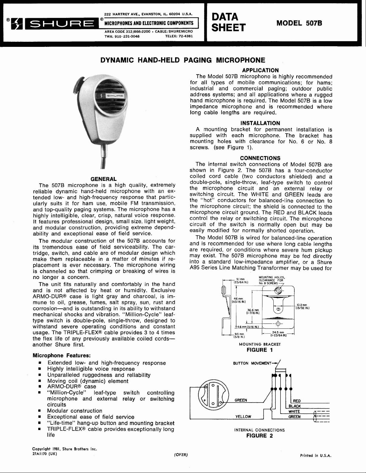
GENERAL
The 5078 microphone is a high quality, extremely
reliable dynamic hand-held microphone with an extended low- and high-frequency response that particularly suits it for ham use, mobile FM transmission,
and top-quality paging systems. The microphone has a
highly intelligible, clear, crisp, natural voice response.
It features professional design, small size, light weight,
and modular construction, providing extreme dependability and exceptional ease of field service.
The modular construction of the 507B accounts for
its tremendous ease of field serviceability. The cartridge, switch, and cable are of modular design which
make them replaceable in a matter of minutes if replacement is ever necessary. The microphone wiring
is channeled so that crimping or breaking of wires is
no longer a concern.
The unit fits naturally and comfortably in the hand
and is not affected by heat or humidity. Exclusive
ARMO-DUR@ case is light gray and charcoal, is immune to oil, grease, fumes, salt spray, sun, rust and
corrosion-and is outstanding in its ability to withstand
mechanical shocks and vibration. "Million-Cycle"
type switch is double-pole, single-throw, designed to
withstand severe operating conditions and constant
usage. The TRIPLE-FLEX@ cable provides
the flex life of any previously available coiled
another Shure first.
Microphone Features:
Extended low- and high-frequency response
Highly intelligible voice response
Unparalleled ruggedness and reliability
Moving coil (dynamic) element
ARMO-DUR@ case
"Million-Cycle" leaf-type switch controlling
microphone and external relay or switching
circuits
Modular construction
Exceptional ease of field service
"Life-time" hang-up button and mounting bracket
TRIPLE-FLEX@ cable provides exceptionally long
life
3
leaf-
to 4 times
cords-
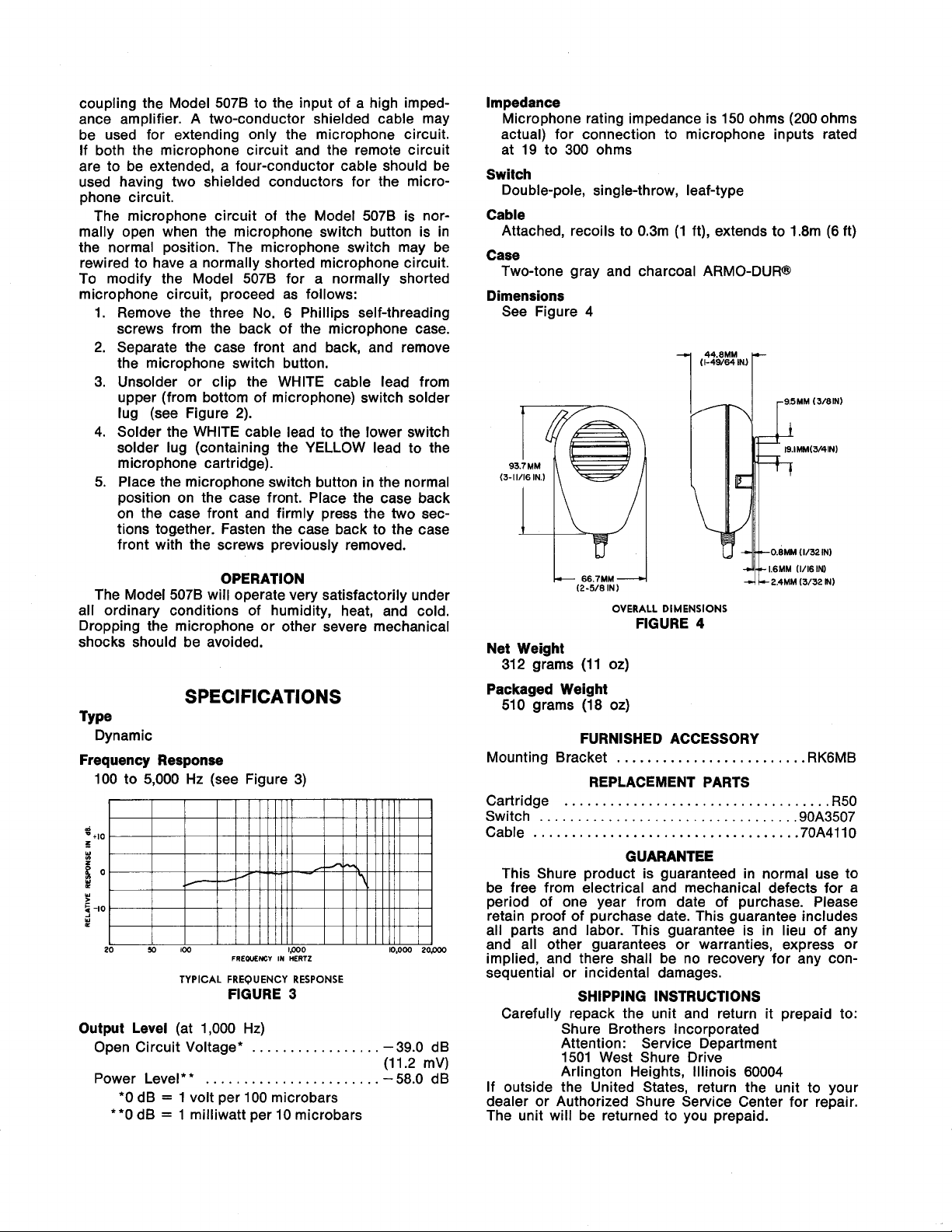
The internal switch connections of Model 507B are
shown in Figure
coiled cord cable (two conductors shielded) and a
double-pole, single-throw, leaf-type switch to control
the microphone circuit and an external relay or
switching circuit. The WHITE and GREEN leads are
the "hot" conductors for balanced-line connection to
the microphone circuit; the shield is connected to the
microphone circuit ground. The RED and BLACK leads
control the relay or switching circuit. The microphone
circuit of the switch is normally open but may be
easily modified for normally shorted operation.
The Model 507B is wired for balanced-line operation
and is recommended for use where long cable lengths
are required, or conditions where severe hum pickup
may exist. The 507B microphone may be fed directly
into a standard low-impedance amplifier, or a Shure
A95 Series Line Matching Transformer may be used for
CONNECTIONS
2.
The 507B has a four-conductor
MOUNTING HOLES,
CLEARANCE FOR
No.
B
SCREWS
-
MOUNTING
BUTTON
BRACKET
FIGURE
MOVEMENT--r
1
k,
1
YELLOW
INTERNAL
FIGURE 2
I
CONNECTIONS
Copyright
27A1170
1981,
(UK)
Shure
Brothers
Inc.
(OVER)
Printed
in
U.S.A.
Page 2
coupling the Model 507B to the input of a high impedance amplifier. A two-conductor shielded cable may
be used for extending only the microphone circuit.
If both the microphone circuit and the remote circuit
are to be extended, a four-conductor cable should be
used having two shielded conductors for the microphone circuit.
The microphone circuit of the Model 507B is normally open when the microphone switch button is in
the normal position. The microphone switch may be
rewired to have a normally shorted microphone circuit.
To modify the Model 507B for a normally shorted
microphone circuit, proceed as follows:
1.
Remove the three No. 6 Phillips self-threading
screws from the back of the microphone case.
2. Separate the case front and back, and remove
the microphone switch button.
3. Unsolder or clip the WHITE cable lead from
upper (from bottom of microphone) switch solder
lug (see Figure 2).
4. Solder the WHITE cable lead to the lower switch
solder lug (containing the YELLOW lead to the
microphone cartridge).
5. Place the microphone switch button in the normal
position on the case front. Place the case back
on the case front and firmly press the two sections together. Fasten the case back to the case
front with the screws previously removed.
Impedance
Microphone rating impedance is 150 ohms (200 ohms
actual) for connection to microphone inputs rated
at 19 to 300 ohms
Switch
Double-pole, single-throw, leaf-type
Cable
Attached, recoils to 0.3m (1 ft), extends to 1.8m (6 ft)
Case
Two-tone gray and charcoal ARMO-DUR@
Dimensions
See Figure
4
(I-49/64
INJ
-I
44.mM
r
OPERATION
The Model 5078 will operate very satisfactorily under
all ordinary conditions of humidity, heat, and cold.
Dropping the microphone or other severe mechanical
shocks should be avoided.
SPECIFICATIONS
TY pe
Dynamic
Frequency Response
100 to 5,000 Hz (see Figure 3)
6
-
+I0
Z
-
s
o
C
W
cj
-I0
W
L
L
20
I I I I l I lllll
50
100 lpO0 lO.000
TYPICAL
FREQUENCY
FREQUENCY
FIGURE
Output Level
Open Circuit Voltage*
Power Level**
*O dB = 1 volt per 100 microbars
**0 dB
(at 1,000 Hz)
.......................
=
1 milliwatt per 10 microbars
.................
IN
HERTZ
RESPONSE
3
I
I l llllll I
J
Pop00
-39.0 dB
(11.2
mV)
-
58.0 dB
OVERALL DIMENSIONS
FIGURE
4
Net Weight
312 grams (11 oz)
Packaged Weight
510 grams (18 oz)
FURNISHED ACCESSORY
Mounting Bracket
.........................
RK6MB
REPLACEMENT PARTS
Cartridge
Switch
Cable
...................................
..................................
...................................
90A3507
70A4110
R50
GUARANTEE
This Shure product is guaranteed in normal use to
be free from electrical and mechanical defects for a
period of one year from date of purchase. Please
retain proof of purchase date. This guarantee includes
all parts and labor. This guarantee is in lieu of any
and all other guarantees or warranties, express or
implied, and there shall be no recovery for any consequential or incidental damages.
SHIPPING INSTRUCTIONS
Carefully repack the unit and return it prepaid to:
Shure Brothers Incorporated
Attention: Service Department
1501 West Shure Drive
Arlington Heights, Illinois 60004
If outside the United States, return the unit to your
dealer or Authorized Shure Service Center for repair.
The unit will be returned to you prepaid.
 Loading...