

Page 1
SHUmB
WE
YWNO
OF
THE
PROfEYlONALS@
MICROPHONES
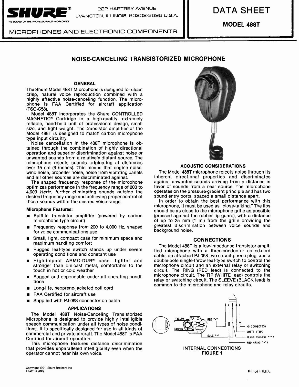
The Shure Model 488T Microphone is designed for clear,
crisp, natural voice reproduction combined with a
highly effective noise-canceling function. The microphone is FAA Certified for aircraft application
(TSO-C58).
Model 488T incorporates the Shure CONTROLLED
MAGNETIC@ Cartridge in a high-quality, extremely
reliable, hand-held unit of professional design, small
size, and light weight. The transistor amplifier of the
Model 488T is designed to match carbon microphone
type input circuitry.
Noise cancellation in the 488T microphone is obtained through the combination of highly directional
operation and superior discrimination against noise or
unwanted sounds from a relatively distant source. The
microphone rejects sounds originating at distances
over 15 cm (6 inches). This means that engine noise,
wind noise, propeller noise, noise from vibrating panels
and all other sources are discriminated against.
The shaped frequency response of the microphone
optimizes performance in the frequency range of 200 to
4,000
desired frequency range and achieving proper control of
those sounds within the desired voice range.
Microphone Features:
Built-in transistor amplifier (powered by carbon
microphone type circuit)
w
Frequency response from 200 to 4,000 Hz, shaped
for voice communications use
Small, light, compact case for minimum space and
maximum handling comfort
Rugged leaf-type switch stands up under severe
operating conditions and constant use
High-impact ARMO-DURB case-lighter and
stronger than die-cast metal, comfortable to the
touch in hot or cold weather
tions
w
Long-life, neoprene-jacketed coil cord
FAA Certified for aircraft use
Supplied with PJ-068 connector on cable
The Model 488T Noise-Canceling Transistorized
Microphone is designed to provide highly intelligible
speech communication under all types of noise
tions. It is specifically designed for use in all kinds of
commercial and private aircraft. The Model 488T is FAA
Certified for aircraft operation.
This microphone features distance discrimination
that provides unparalleled intelligibility even when the
operator cannot hear his own voice.
UIORLWIDE
Hertz, further eliminating sounds outside the
and
222
HARTREY AVENUE
EVANSTON, ILLINOIS 60202-3696 ".s.A.
AND
ELECTRONIC
COMPONENTS
NOISE-CANCELING TRANSISTORIZED MICROPHONE
GENERAL
ACOUSTIC CONSIDERATIONS
The Model 488T microphone rejects noise through its
inherent directional properties and discriminates
against unwanted sounds arriving from a distance in
favor of sounds from a near source. The microphone
operates on the pressure-gradient principle and has two
sound entry ports, spaced a small distance apart.
In order to obtain the best performance with this
microphone, it must be used as "close-talking." The lips
should be as close to the microphone grille as possible
(pressed against the rubber lip guard), with a distance
of up to 25 mm (1 in.) from the grille providing the
greatest discrimination between voice sounds and
background noise.
CONNECTIONS
The Model 488T is a low-impedance transistor-amplified microphone with a three-conductor coiled-cord
cable, an attached PJ-068 two-circuit phone plug, and a
double-pole single-throw leaf-type switch to control the
dependable
APPLICATIONS
under
all
operating
condi.
condi-
microphone circuit and an external relay or switching
circuit. The
microphone circuit.
relay or switching circuit. The SLEEVE (BLACK lead) is
common to the microphone and relay circuits.
RING (RED lead) is connected to the
he
INTERNAL CONNECTIONS
FIGURE
DATA SHEET
MODEL
TIP (WHITE lead) controls the
1
488T
NO CONNECTION
WHITE (TIP)
BLACK (SLEEUE
RED (RING
-+.)
"-"
)
Copyright 1991, Shure Brothers
27A2517
(KK)
Inc.
Printed in U.S.A.
Page 2
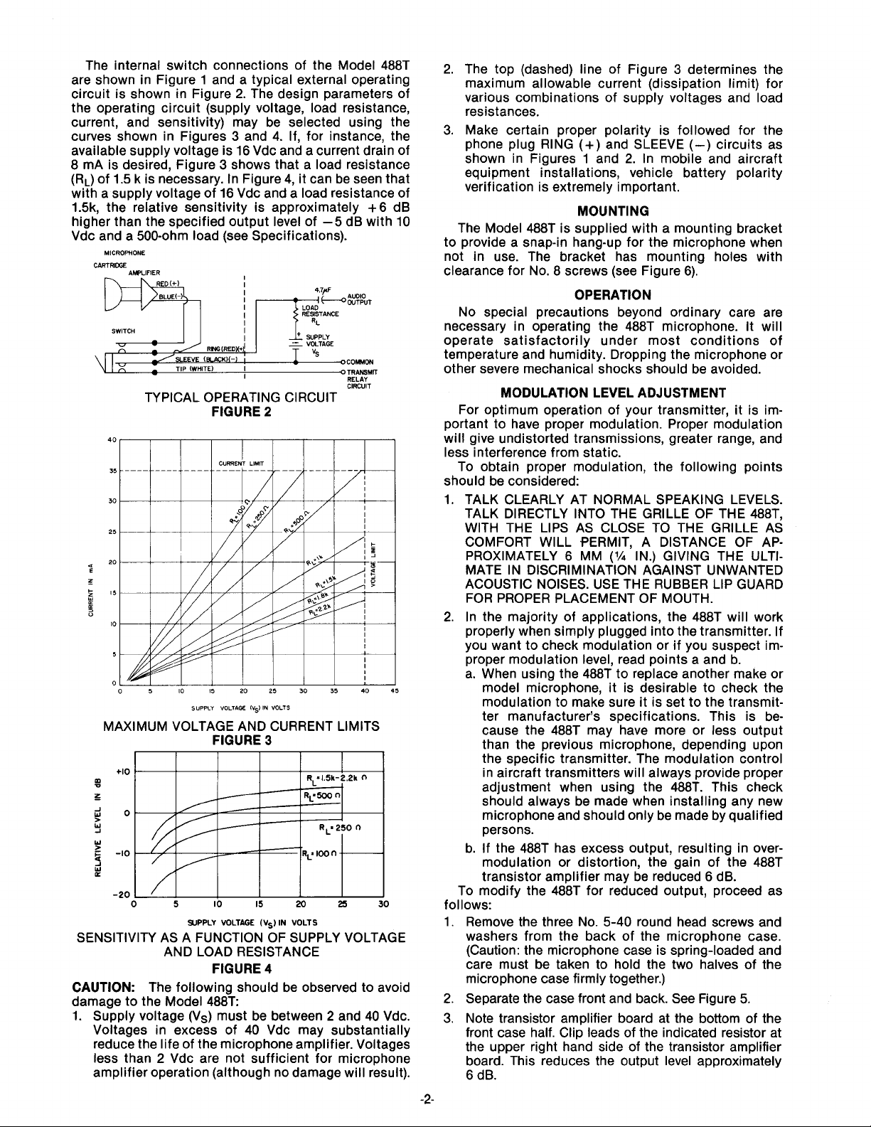
The internal switch connections of the Model 488T
are shown in Figure 1 and a typical external operating
2.
circuit is shown in Figure
The design parameters of
the operating circuit (supply voltage, load resistance,
current, and sensitivity) may be selected using the
3
curves shown in Figures
and 4. If, for instance, the
available supply voltage is 16 Vdc and a current drain of
mA is desired, Figure 3 shows that a load resistance
8
(RL) of 1.5 k is necessary. In Figure 4, it can be seen that
with a supply voltage of 16 Vdc and a load resistance of
1.5k, the relative sensitivity is approximately + 6 dB
higher than the specified output level of -5 dB with 10
Vdc and a 500-ohm load (see Specifications).
MICROPHONE
CARTMOOE
AMPLIFIER
mT
RED(+)
BLUE(-)
1
m:-&?PuT
I
I
REsIsTwE
-
VOLTAGE
-
4.7pF
OCOMMON
0
TRANSMIT
RELAY
rlfftll~
-
.. . - -. .
TYPICAL OPERATING CIRCUIT
FIGURE
SUPFVY
VOLTAGE iVs)
2
IN
VOLTS
MAXIMUM VOLTAGE AND CURRENT LIMITS
FIGURE 3
I
SUPPLY VOLTAGE (VS)
IN
VOLTS
1
SENSITIVITY AS A FUNCTION OF SUPPLY VOLTAGE
AND LOAD RESISTANCE
CAUTION:
The following should be observed to avoid
damage to the Model
FIGURE
488T:
4
1. Supply voltage (Vs) must be between 2 and 40 Vdc.
Voltages in excess of 40 Vdc may substantially
reduce the life of the microphone amplifier. Voltages
less than
2
Vdc are not sufficient for microphone
amplifier operation (although no damage will result).
2.
The top (dashed) line of Figure 3 determines the
maximum allowable current (dissipation limit) for
various combinations of supply voltages and load
resistances.
3.
Make certain proper polarity is followed for the
phone plug
shown in Figures 1 and
RING
(+)
and SLEEVE
(-)
circuits as
2.
In mobile and aircraft
equipment installations, vehicle battery polarity
verification is extremely important.
MOUNTING
The Model 488T is supplied with a mounting bracket
to provide a snap-in hang-up for the microphone when
not in use. The bracket has mounting holes with
clearance for No. 8 screws (see Figure 6).
OPERATION
No special precautions beyond ordinary care are
necessary in operating the 488T microphone. It will
operate satisfactorily under most conditions of
temperature and humidity. Dropping the microphone or
other severe mechanical shocks should be avoided.
MODULATION LEVEL ADJUSTMENT
For optimum operation of your transmitter, it is important to have proper modulation. Proper modulation
will give undistorted transmissions, greater range, and
less interference from static.
To obtain proper modulation, the following points
should be considered:
1. TALK CLEARLY AT NORMAL SPEAKING LEVELS.
TALK DIRECTLY INTO THE GRILLE OF THE
WITH THE LIPS AS CLOSE TO THE GRILLE AS
COMFORT
PROXIMATELY 6 MM
WILL PERMIT, A DISTANCE OF AP-
('A
IN.) GIVING THE ULTI-
MATE IN DISCRIMINATION AGAINST UNWANTED
ACOUSTIC NOISES. USE THE RUBBER LIP GUARD
FOR PROPER PLACEMENT OF MOUTH.
2.
In the majority of applications, the 488T will work
properly when simply plugged into the transmitter. If
you want to check modulation or if you suspect im-
proper modulation level, read points a and b.
a. When using the 488T to replace another make or
model microphone, it is desirable to check the
modulation to make sure it is set to the transmitter manufacturer's specifications. This is because the 488T may have more or less output
than the previous microphone, depending upon
the specific transmitter. The modulation control
in aircraft transmitters will always provide proper
adjustment when using the
488T. This check
should always be made when installing any new
microphone and should only be made by qualified
persons.
b. If the 488T has excess output, resulting in
modulation or distortion, the gain of the 488T
transistor amplifier may be reduced 6 dB.
To modify the 488T for reduced output, proceed as
follows:
1. Remove the three No. 5-40 round head screws and
washers from the back of the microphone case.
(Caution: the microphone case is spring-loaded and
care must be taken to
hold the two halves of the
microphone case firmly together.)
2.
Separate the case front and back. See Figure
3.
Note transistor amplifier board at the bottom of the
front case half. Clip leads of the indicated resistor at
the upper right hand side of the transistor amplifier
board. This reduces the output level approximately
6
dB.
-2-
488T,
over-
5.
Page 3

To reassemble microphone proceed as follows:
1. Be certain that the cartridge shield retaining springs
are in proper position.
2. Place case back on case front and firmly press
cases together; fasten with the three No. 5-40
screws and washers previously removed.
DC Supply Voltage and Current
2 to 40 Vdc (see Figure 3)
*
*I0
SWITCH BUTTON
CASE BACK CASE FRONT
\
Ld
MU-METAL
SHIELD^
FIGURE
TRANSISTOR WPLlFlER
BOARD
5
/
OUTPUT LEVEL
FAA CERTIFICATION
The Model 488T is FAA certified for aircraft use and is
within the FAA
TSO-C58 requirements. To maintain this
FAA certification, any service required for the Model
488T must be performed by Shure Brothers Inc. or by an
FAA approved service facility.
m(293)zlN
)
MOUNTING HOLES,
CLEaRdKF
8
SCREWS
FOR
-
--
-
k
Q
%
-10
L
PO
Y)
IM)
FREWNCY
IN
+Po0
HERTZ
TYPICAL FREQUENCY RESPONSE
FIGURE
7
Switch
Double-pole, single-throw, leaf-type, push-to-talk
Cable
Nondetachable,
1.7m (5% ft), 3-conductor, tinsel,
neoprene-jacketed, coil cord with PJ-068 2-circuit
phone plug on equipment end
Case
High-impact
ARMO-DUR@ with perforated steel grille
and rubber lip guard
Dimensions
See Figure 8
MOUNTING BRACKET
FIGURE
6
SPECIFICATIONS
TY pe
CONTROLLED MAGNETIC@, Noise-Canceling (with
transistor amplifier)
Frequency Response
200 to 4,000 Hz (see Figure
Load Impedance Range
100 to 2,200 ohms (see Figures
Output level (at 1,000 Hz, 5116 in.)
-5.0 dB
(560 V) with 10 Vdc, 500-ohm load
(0 dB = 1 volt per 100 microbars) (See Figure 4)
7)
3
and 4)
OVERALL DIMENSIONS
FIGURE
8
Net Weight
340 grams (12
oz)
Packaged Weight
510 grams (18 oz)
Certification
FAA certified for aircraft use within TSO-C58
FURNISHED ACCESSORY
Mounting Bracket
(3
in kit).
...................
RK6MB
REPLACEMENT PARTS
Cartridge Assembly R88T
Switch
Cable C22C
.................................
.....................................
.........................
90A2990
 Loading...