

Page 1
A
222 HARTREY AVE.. EVANSTON, IL. 60204 U.S.A.
8
AREA CODE 312/866-2200 . CABLE: SHUREMICRO
TWX: 910.231-0048 TELEX: 72.4381
DATA
SHEET
MODELS 407A
CONTROLLED MAGNETIC@ HAND MICROPHONES
inputs, the 4078 for amplifiers with low-impedance inputs.
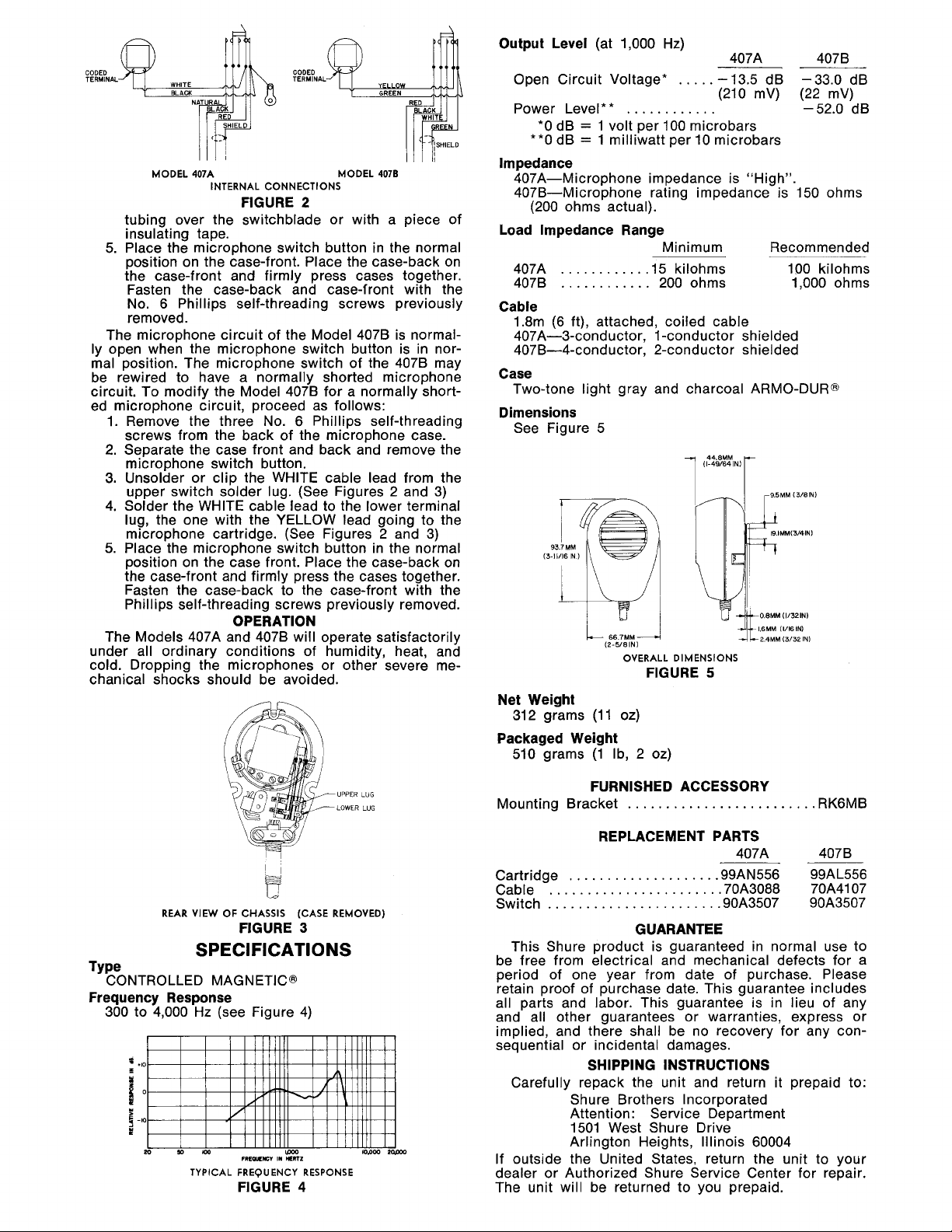
supplied with each microphone. (See Figure
INSTALLATION AND CONNECTIONS
A mounting bracket for permanent installation is
MOUNTING HOLES,
CLEARANCE FOR
No.
8
SCREWS
and
4078
1)
7
10.2
rnrn
(13/32
IN.)
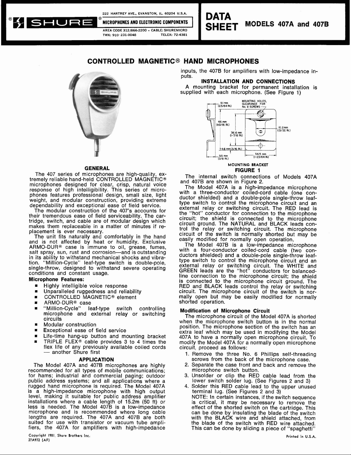
GENERAL
The 407 series of microphones are high-quality, ex-
tremely reliable hand-held CONTROLLED
MAGNETIC@
microphones designed for clear, crisp, natural voice
response of high intelligibility. This series of microphones features professional design, small size, light
weight, and modular construction, providing extreme
dependability and exceptional ease of field service.
The modular construction of the 407's accounts for
their tremendous ease of field serviceability. The cartridge, switch, and cable are of modular design which
makes them replaceable in a matter of minutes if replacement is ever necessary.
The unit fits naturally and comfortably in the hand
and is not affected by heat or humidity. Exclusive
ARMO-DUR@ case is immune to oil, grease, fumes,
salt spray, sun, rust and corrosion-and is outstanding
in its ability to withstand mechanical shocks and vibration. "Million-Cycle" leaf-type switch is double-pole,
single-throw, designed to withstand severe operating
conditions and constant usage.
Microphone Features:
Highly intelligible voice response
Unparalleled ruggedness and reliability
=
CONTROLLED MAGNETIC@ element
=
ARMO-DURe case
"Million-Cycle" leaf-type switch controlling
microphone and external relay or switching
circuits
Modular construction
Exceptional ease of field service
Life-time hang-up button and mounting bracket
TRIPLE FLEX@ cable provides 3 to 4 times the
flex life of any previously available coiled cords
-
another Shure first
APPLICATION
The Model 407A and 407B microphones are highly
recommended for all types of mobile communications;
for hams; industrial and commercial paging; outdoor
public address systems; and all applications where a
rugged hand microphone is required. The Model 407A
is a high-impedance microphone with high output
level, making it suitable for public address amplifier
installations where a cable length of
15.2m (50 ft) or
less is needed. The Model 407B is a low-impedance
microphone and is recommended where long cable
lengths are required. The 407A and 407B are both
suited for use with transistor or vacuum tube amplifiers, the 407A for amplifiers with high-impedance
Copyright 1981, Shure Brothers
27A972 (AF)
Inc.
MOUNTING BRACKET
FIGURE
1
The internal switch connections of Models 407A
and 407B are shown in Figure 2.
The Model 407A is a high-impedance microphone
with a three-conductor coiled-cord cable (one conductor shielded) and a double-pole single-throw leaftype switch to control the microphone circuit and an
external relay or switching circuit. The RED lead is
the "hot" conductor for connection to the microphone
circuit; the shield is connected to the microphone
circuit ground. The NATURAL and BLACK leads control the relay or switching circuit. The microphone
circuit of the switch is normally shorted but may be
easily modified for normally open operation.
The Model 407B is a low-impedance microphone
with a four-conductor coiled-cord cable (two conductors shielded) and a double-pole single-throw leaftype switch to control the microphone circuit and an
external relay or switching circuit. The WHITE and
GREEN leads are the "hot" conductors for
balancedline connection to the microphone circuit; the shield
is connected to the microphone circuit ground. The
RED and BLACK leads control the relay or switching
circuit. The microphone circuit of the switch is normally open but may be easily modified for normally
shorted operation.
Modification of Microphone Circuit
The microphone circuit of the Model 407A is shorted
when the microphone switch button is in the normal
position. The microphone section of the switch has an
extra leaf which may be used in modifying the Model
407A to have a normally open microphone circuit. To
modify the Model 407A for a normally open microphone
circuit, proceed as follows:
1.
Remove the three No. 6 Phillips self-threading
screws from the back of the microphone case.
2. Separate the case front and back and remove the
microphone switch button.
3. Unsolder or clip the RED cable lead from the
lower switch solder lug. (See Figures 2 and 3)
4. Solder this RED cable lead to the upper unused
2
terminal lug. (See Figures
and 3)
NOTE: In certain instances, if the switch sequence
is critical, it may be necessary to remove the
effect of the shorted switch on the cartridge. This
can be done by insulating the blade of the switch
with the BLACK wire and shield attached, from
the blade of the switch with RED wire attached.
This can be done by sliding a piece of "spaghetti"
Printed
in
U.S.A.
Page 2
CODED
TERMINAL
MODEL
407A
INTERNAL
CONNECTIONS
MODEL
4078
FIGURE 2
tubing over the switchblade or with a piece of
insulating tape.
5.
Place the microphone switch button in the normal
position on the case-front. Place the case-back on
the case-front and firmly press cases together.
Fasten the case-back and case-front with the
No. 6 Phillips self-threading screws previously
removed.
The microphone circuit of the Model
4078 is normally open when the microphone switch button is in normal position. The microphone switch of the
4078 may
be rewired to have a normally shorted microphone
circuit. To modify the Model 407B for a normally shorted microphone circuit, proceed as follows:
1. Remove the three No.
6
Phillips self-threading
screws from the back of the microphone case.
2. Separate the case front and back and remove the
microphone switch button.
3.
Unsolder or clip the WHITE cable lead from the
upper switch solder lug. (See Figures 2 and 3)
4. Solder the WHITE cable lead to the lower terminal
lug, the one with the YELLOW lead going to the
microphone cartridge. (See Figures 2 and 3)
5.
Place the microphone switch button in the normal
position on the case front. Place the case-back on
the case-front and firmly press the cases together.
Fasten the case-back to the case-front with the
Phillips self-threading screws previously removed.
OPERATION
The Models 407A and 4078 will operate satisfactorily
under all ordinary conditions of humidity, heat, and
cold. Dropping the microphones or other severe mechanical shocks should be avoided.
Output Level
(at 1,000
Hz)
407A 4078
Open Circuit Voltage*
Power Level
*
*
............
.....
-13.5 dB -33.0 dB
(210
mV) (22 mV)
-52.0 dB
*O dB = 1 volt per 100 microbars
**0 dB
=
1 milliwatt per 10 microbars
Impedance
407A-Microphone impedance is "High".
407B-Microphone rating impedance is 150 ohms
(200 ohms actual).
Load lmpedance Range
Minimum Recommended
407A
407B
...........
.15 kilohms 100 kilohms
............
200 ohms 1,000 ohms
Cable
1.8m
(6
ft), attached, coiled cable
407A-3-conductor, 1-conductor shielded
407B-4-conductor, 2-conductor shielded
Case
Two-tone light gray and charcoal ARMO-DUR@
Dimensions
See Figure 5
Ak
~MM (11161N)
(2-5/81Nl
OVERALL
DIMENSIONS
24MM (3/32 IN1
FIGURE 5
Net Weight
312 grams (1 1 oz)
Packaged Weight
510 grams (1 Ib, 2 oz)
F
REAR
VIEW
OF
CHASSIS
FIGURE
SPECIFICATIONS
Frequency Response
300 to 4,000 Hz (see Figure 4)
=
.,o
1
o
5
-10
TYPICAL
FREOUW
FREQUENCY
FIGURE
I*
lpoo
*Lmz
(CASE
4
UPPER LUG
LOWER LUG
REMOVED)
3
RESPONSE
FURNISHED ACCESSORY
Mounting Bracket
.........................
RK6MB
REPLACEMENT PARTS
407A 4078
Cartridge .99AN556 99AL556
Cable .70A3088 70A4107
Switch .90A3507 90A3507
...................
......................
......................
GUARANTEE
This Shure product is guaranteed in normal use to
be free from electrical and mechanical defects for a
period of one year from date of purchase. Please
retain proof of purchase date. This guarantee includes
all parts and labor. This guarantee is in lieu of any
and all other guarantees or warranties, express or
implied, and there shall be no recovery for any consequential or incidental damages.
SHIPPING INSTRUCTIONS
Carefully repack the unit and return it prepaid to:
Shure Brothers Incorporated
Attention: Service Department
1501 West Shure Drive
Arlington Heights, Illinois 60004
If outside the United States, return the unit to your
dealer or Authorized Shure Service Center for repair.
The unit will be returned to you prepaid.
 Loading...