

Page 1
SMU-
THE SOUND OF THE PROFESSIONALSS WORLDWIDE
MICROPHONES
J
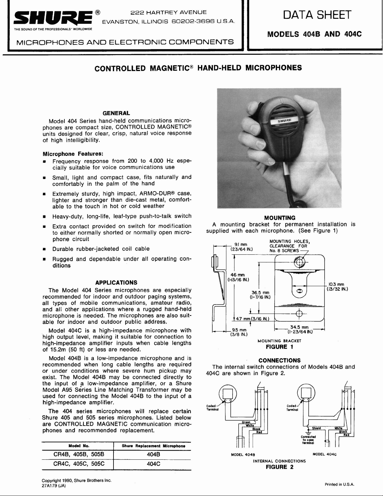
Model 404 Series hand-held communications microphones are compact size, CONTROLLED MAGNETIC@
units designed for clear, crisp, natural voice response
of high intelligibility.
Microphone Features:
Frequency response from 200 to 4,000 Hz especially suitable for voice communications use
Small, light and compact case, fits naturally and
comfortably in the palm of the hand
=
Extremely sturdy, high impact, ARMO-DURB case,
lighter and stronger than die-cast metal, comfortable to the touch in hot or cold weather
Heavy-duty, long-life, leaf-type push-to-talk switch
Extra contact provided on switch for modification
to either normally shorted or normally open micro-
phone circuit
Durable rubber-jacketed coil cable
D
Rugged and dependable under all operating conditions
The Model 404 Series microphones are especially
recommended for indoor and outdoor paging systems,
all types of mobile communications, amateur radio,
and all other applications where a rugged hand-held
microphone is needed. The microphones are also suit-
able for indoor and outdoor public address.
Model 404C is a high-impedance microphone with
high output level, making it suitable for connection to
high-impedance amplifier inputs when cable lengths
15.2m (50 ft) or less are needed.
of
Model 4048 is a low-impedance microphone and is
recommended when long cable lengths are required
or under conditions where severe hum pickup may
exist. The Model 4048 may be connected directly to
the input of
Model A95 Series Line Matching Transformer may be
used for connecting the Model 4048 to the input of a
high-impedance amplifier.
The 404 series microphones will replace certain
Shure 405 and 505 series microphones. Listed below
are CONTROLLED MAGNETIC communication microphones and recommended replacement.
222
HARTREY AVENUE
@
EVANSTON. ILLINOIS 60202-3696 U.S.A.
MODELS 404B AND 404C
AND
ELECTRONIC COMPONENTS
CONTROLLED MAGNETIC' HAND-HELD MICROPHONES
GENERAL
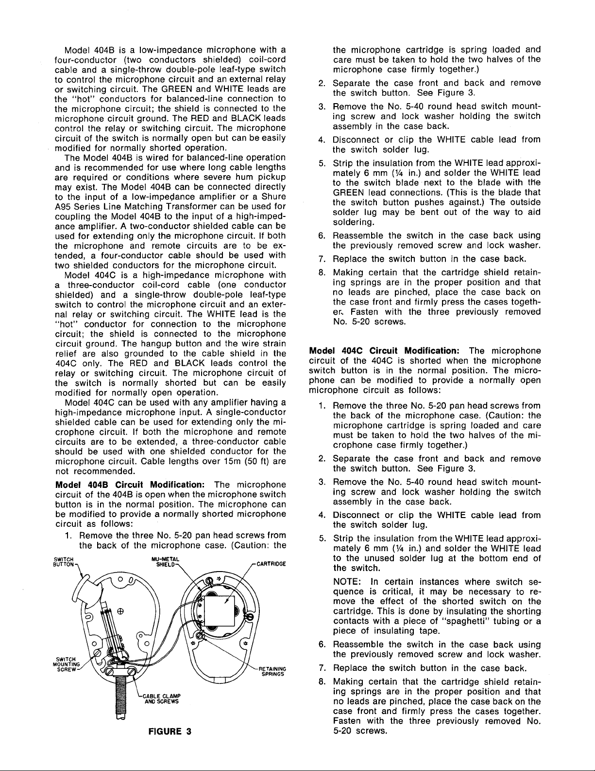
MOUNTING
A mounting bracket for permanent installation is
supplied with each microphone. (See Figure
MOUNTING
CLEARANCE
No.
46
mm
APPLICATIONS
a
low-impedance amplifier, or a Shure
404C are shown in Figure 2.
(C13/16 IN.)
36.5
mm
(1-7116 IN.)
4.7
mm
(3/16 IN.)
t
/l~
The internal switch connections of Models 4048 and
mm
(3/8 IN.) c(l-23/64
MOUNTING
FIGURE
CONNECTIONS
DATA
HOLES,
SCREWS
FOR
7
8
-
34.5
mm
BRACKET
1
SHEET
10.3
(13/32 IN.)
J
4
INI
1)
mm
Model No.
CR4B, 4058, 5058
CR4C, 405C, 505C
Copyright 1990, Shure Brothers
27A179 (JA)
Shure Replacement Microphone
4048
404C
Inc
MODEL 404B MODEL 404C
INTERNAL
CONNECTIONS
FIGURE
2
Printed
in
U.S.A.
Page 2
Model 4048 is a low-impedance microphone with a
four-conductor (two conductors shielded) coil-cord
cable and a single-throw double-pole leaf-type switch
to control the microphone circuit and an external relay
or switching circuit. The GREEN and WHlTE leads are
the "hot" conductors for balanced-line connection to
the microphone circuit; the shield is connected to the
microphone circuit ground. The RED and BLACK leads
control the relay or switching circuit. The microphone
circuit of the switch is normally open but can be easily
modified for normally shorted operation.
The Model 4048 is wired for balanced-line operation
and is recommended for use where long cable lengths
are required or conditions where severe hum pickup
may exist. The Model 4048 can be connected directly
to the input of a low-impedance amplifier or a Shure
A95 Series Line Matching Transformer can be
coupling the Model 4048 to the input of a
used for
high-impedance amplifier. A two-conductor shielded cable can be
used for extending only the microphone circuit. If both
the microphone and remote circuits are to be extended, a four-conductor cable should be used with
two shielded conductors for the microphone circuit.
Model 404C is a high-impedance microphone with
a three-conductor coil-cord cable (one conductor
shielded) and a single-throw double-pole leaf-type
switch to control the microphone circuit and an external relay or switching circuit. The WHlTE lead is the
"hot" conductor for connection to the microphone
circuit; the shield is connected to the microphone
circuit ground. The
hangup button and the wire strain
relief are also grounded to the cable shield in the
404C only. The RED and BLACK leads control the
relay or switching circuit. The microphone circuit of
the switch is normally shorted but can be easily
modified for normally open operation.
Model 404C can be used with any amplifier having a
high-impedance microphone input. A single-conductor
shielded cable can be used for extending only the microphone circuit. If both the microphone and remote
circuits are to be extended, a three-conductor cable
should be used with one shielded conductor for the
microphone circuit. Cable lengths over
15m (50 ft) are
not recommended.
Model
circuit of the
4048
Circuit Modification:
The microphone
4048 is open when the microphone switch
button is in the normal position. The microphone can
be modified to provide a normally shorted microphone
circuit as follows:
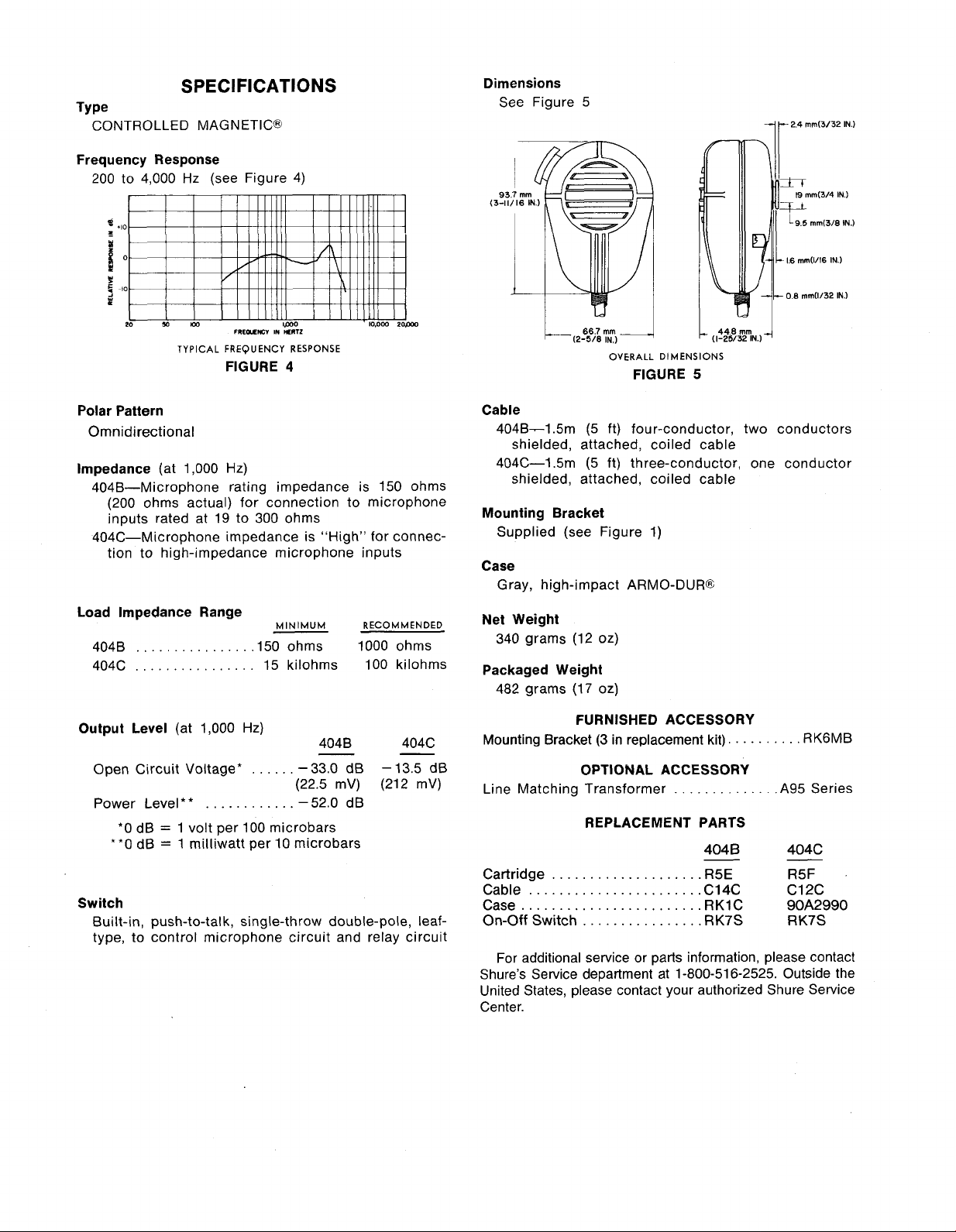
1.
Remove the three No. 5-20 pan head screws from
the back of the microphone case. (Caution: the
SWITCH
BUTTON,
w
MU-METAL
SHIELD7
FIGURE
3
the microphone cartridge is spring loaded and
care must be taken to hold the two halves of the
microphone case firmly together.)
2. Separate the case front and back and remove
the switch button. See Figure
3.
Remove the No. 5-40 round head switch mount-
3.
ing screw and lock washer holding the switch
assembly in the case back.
4. Disconnect or clip the WHlTE cable lead from
the switch solder lug.
5. Strip the insulation from the WHITE lead approxi-
6
mm
(Y4
mately
to the switch blade next to the blade with
in.) and solder the WHlTE lead
ttle
GREEN lead connections. (This is the blade that
the switch button pushes against.) The outside
solder lug may be bent out of the way to aid
soldering.
6.
Reassemble the switch in the case back using
the previously removed screw and lock washer.
7.
Replace the switch button in the case back.
8.
Making certain that the cartridge shield retaining springs are in the proper position and that
no leads are pinched, place the case back on
the case front and firmly press the cases together.. Fasten with the three previously removed
No. 5-20 screws.
Model
404C
Circuit Modification:
The microphone
circuit of the 404C is shorted when the microphone
switch button is in the normal position. The microphone can be modified to provide a normally open
microphone circuit as follows:
1. Remove the three No. 5-20 pan head screws from
the back of the microphone case. (Caution: the
microphone cartridge is spring loaded and care
must be taken to hold the two halves of the mi-
crophone case firmly together.)
2. Separate the case front and back and remove
the switch button. See Figure
3.
Remove the No. 5-40 round head switch mount-
3.
ing screw and lock washer holding the switch
assembly in the case back.
4. Disconnect or clip the WHlTE cable lead from
the switch solder lug.
5. Strip the insulation from the WHlTE lead approxi-
6
mm
(Y4
mately
in.) and solder the WHlTE lead
to the unused solder lug at the bottom end of
the switch.
NOTE: In certain instances where switch se-
quence is critical, it may be necessary to re-
move the effect of the shorted switch on the
cartridge. This is done by insulating the shorting
contacts with a piece of "spaghetti" tubing or a
piece of insulating tape.
6.
Reassemble the switch in the case back using
the previously removed screw and lock washer.
7.
Replace the switch button in the case back.
8. Making certain that the cartridge shield retaining springs are in the proper position and that
no leads are pinched, place
€he case back on the
case front and firmly press the cases together.
Fasten with the three previously removed No.
5-20 screws.
Page 3
SPECIFICATIONS
TY Pe
CONTROLLED MAGNETIC@
Frequency Response
200 to 4,000 Hz (see Figure 4)
FRLOTNC*
TYPICAL
FREQUENCY
FIGURE
IN
lERlZ
RESPONSE
4
Dimensions
See Figure 5
OVERALL
FIGURE
DIMENSIONS
5
7
t
2.4 mm(3/32 IN.)
0.8
mm(1/32 IN.)
Polar Pattern
Omnidirectional
lmpedance
(at 1,000 Hz)
404B-Microphone rating impedance is 150 ohms
(200 ohms actual) for connection to microphone
inputs rated at 19 to 300 ohms
404C-Microphone impedance is "High" for connec-
tion to high-impedance microphone inputs
Load lmpedance Range
404B
...............
................
404C
Output Level
(at 1,000
Open Circuit Voltage*
Power Level**
*O
dB = 1 volt per 100 microbars
**0 dB
............
=
1 milliwatt per 10 microbars
MINIMUM
RECOMMENDED
,150 ohms 1000 ohms
15 kilohms 100 kilohms
Hz)
404B 404C
......
-
-
33.0 dB - 13.5 dB
(22.5
mV) (212 mV)
-
-52.0 dB
Switch
Built-in, push-to-talk, single-throw double-pole, leaftype, to control microphone circuit and relay circuit
Cable
404B-1.5m (5 ft) four-conductor, two conductors
shielded, attached, coiled cable
404C-1.5m (5 ft) three-conductor, one conductor
shielded, attached, coiled cable
Mounting Bracket
Supplied (see Figure 1)
Case
Gray, high-impact ARMO-DUR@
Net Weight
340 grams (12 oz)
Packaged Weight
482 grams (17 oz)
FURNISHED ACCESSORY
Mounting Bracket
(3
in replacement kit).
.........
RK6MB
OPTIONAL ACCESSORY
Line Matching Transformer .A95 Series
.............
REPLACEMENT PARTS
404
Cartridge
Cable
Case
On-Off
....................
.......................
........................
Switch
................
B
-
R5E R5F
C14C C12C
RK1C
RK7S RK7S
404C
-
90A2990
For additional service or parts information, please contact
Shure's Service department at 1-800-51 6-2525. Outside the
United
States, please contact your authorized Shure Service
Center.
 Loading...