

Page 1

222HARTREYAVENUE
SHUeB
THE
SOUNO
OF THE
PAOFESSlONALS~
UlORLWlDE
EVANSTON, ILLINOIS 80202-3696 U.S.A.
MICROPHONES AND ELECTRONIC COMPONENTS
_t
CONTROLLED MAGNETICB COMMUNICATIONS MICROPHONES
GENERAL
The Shure 401 Series hand-held communications
microphones are compact size, CONTROLLED
MAGNETIC@ units designed for clear, crisp, natural
voice response of high intelligibility.
Microphone Features:
w
Frequency response from 200 to 4,000 Hz especially
suitable for voice communications use
w
Small, light and compact case, fits comfortably and
firmly in the palm of the hand
w
Extremely sturdy, high impact, ARMO-DUR@ case,
lighter and stronger than die-cast metal, comfortable
to the touch in hot or cold weather
w
Heavy-duty, long-life, push-to-talk switch
w
Durable rubber-jacketed coil cable
w
Rugged and dependable under all operating conditions
APPLICATIONS
The 401 Series microphones are especially recommended for all types of outdoor-indoor communication
activity: in mobile and fixed station use (as in police,
fire, utility, forestry, and transportation services), and in
commercial and industrial applications-including
radiotelephone, amateur radio, and similar uses. The
microphones are also suitable for indoor and outdoor
public address.
The 401A is a high-impedance microphone with high
10.3
(13/32
mm
IN.)
high-
output level, making it suitable for connection to
impedance amplifier inputs when cable lengths of
15.2m (50 ft) or less are needed.
The 401B is a low-impedance microphone and is
recommended when long cable lengths are required or
under conditions where severe hum pickup may exist.
4018 can be connected directly to the input of a
The
low-impedance amplifier, or a Shure A95 Series Line
Matching Transformer can be used for connecting the
401B to the input of a high-impedance amplifier (additional connector required).
MOUNTING
A mounting bracket for permanent installation is sup-
-
mm
IN)
1)
4
plied with each microphone. (See Figure
MOUNTING HOLES,
CLEARANCE FOR
No
8
SCREWS
19.5
mm
(3/8
IN.)
MOUNTING BRACKET
L(1-23/64
FIGURE
34.5
1
DATA
MODELS
CONNECTIONS
The internal switch connections of the 401A and 401 B
are shown in Figure
MODEL 401A MODEL 4010
The 401A is a high-impedance microphone with a
three-conductor, coiled-cord cable (one conductor
shielded), and a double-pole, double-throw switch to
control the microphone circuit and an external relay or
switching circuit. The WHITE lead is the "hot" conductor for connection to the microphone circuit ground. The
RED and BLACK leads control the relay or switching cir-
cuit.
4018 is a low-impedance microphone with a four-
The
conductor, coiled-cord cable (two conductors shielded),
and a double-pole double-throw switch to control the
microphone circuit and an external relay or switching
circuit. The GREEN and WHITE leads are the "hot" conductors for balanced-line connection to the microphone
circuit; the shield is connected to the microphone circuit ground. The RED and BLACK leads control the relay
or switching circuit.
2.
INTERNAL CONNECTIONS
FIGURE
2
SHEET
401A
and
401
B
Copyright 1993, Shure Brothers Inc.
27A198
(MD)
Printed in U.S.A.
Page 2
OPERATION
No special precautions beyond ordinary care are
necessary in operation of 401 microphones. They will
function very satisfactorily under all ordinary conditions of humidity, heat, and cold. Dropping the
microphones or other severe mechanical shocks should
be avoided.
SPECIFICATIONS
Type
CONTROLLED MAGNETICB
Frequency Response
200 to 4,000 Hz (see Figure 3)
I
I
Y
I
1
I
20 50 100 lpo0 l0.000
111111
FREQUENCY
IN
HERTZ
I
l
1
llllll
1
I
now
Cable
401A-1.5m (5 ft) three-conductor, one conductor
shielded, attached, coiled cable
401 B
-
1.8m (6 ft) four-conductor, two conductors
shielded, attached, coiled cable
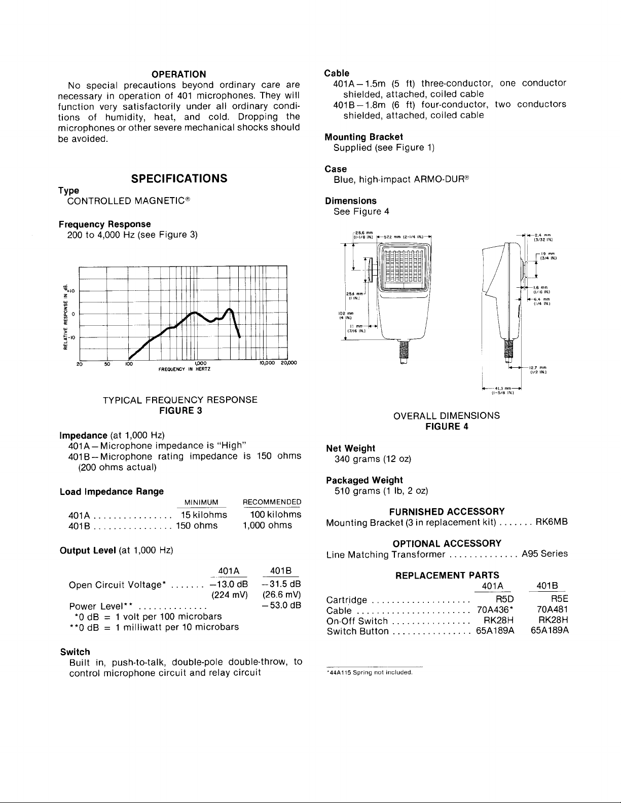
Mounting Bracket
Supplied (see Figure 1)
Case
Blue, high-impact ARMO-DURn
Dimensions
See Figure 4
TYPICAL FREQUENCY RESPONSE
lmpedance
FIGURE
(at 1,000 Hz)
3
401A- Microphone impedance is "High"
401B-Microphone rating impedance is 150 ohms
(200 ohms actual)
Load lmpedance Range
MINIMUM
................
401A 15 kilohms 100 kilohms
................
4018 150 ohms 1,000 ohms
Output Level
Open Circuit Voltage* -13.0 dB -31.5 dB
(at 1,000 Hz)
.......
(224
Power Level
*
*
..............
RECOMMENDED
A01 A 401 B
-
mV) (26.6 mV)
-
53.0 dB
*O dB = 1 volt per 100 microbars
**0 dB
=
1 milliwatt per 10 microbars
Switch
Built in, push-to-talk, double-pole double-throw, to
control microphone circuit and relay circuit
OVERALL DIMENSIONS
FIGURE
4
Net Weight
340 grams (12 oz)
Packaged Weight
510 grams (1 Ib, 2 oz)
FURNISHED ACCESSORY
Mounting Bracket (3 in replacement kit)
.......
RK6MB
OPTIONAL ACCESSORY
Line Matching Transformer A95 Series
..............
REPLACEMENT PARTS
401 A 401 B
-
Cartr,idge
Cable
On-Off Switch
Switch Button 65A189A 65A189A
'44A115
....................
.......................
................
................
Spr~ng not included.
R5D R5E
70A436* 70A481
RK28H R K28 H
-
 Loading...