

Page 1
Beta 53
User Guide
HEADWORN MICROPHONES
2002, Shure Incorporated
27C3115 (BF)
Printed in U.S.A.
Page 2

ENGLISH
GENERAL
The Shure Beta 5 3 i s a s ubminiature, e lectret c ondenser headworn m icrophone. It is
intended for w ireless u se i n s ound r einforcement a pplications t hat r equire m inimal v isibility and maximum mobility, such as stage performances.
Despite its small size, the microphone element provides full, articulate reproduction
of speech and vocals, and features an omnidirectional pick-up pattern.
The Bet a 5 3 c o n si s ts of an adjustable wireframe a nd boom that allows flexible p lacement of t he m icrophone c artridge. It is a ls o s upplied w ith t wo d ifferent e qualization c aps
that tailor the microphone’s high-frequency response. Acoustic windscreens are supplied to minimize wind noise.
MODEL VARIATIONS
WBH53B: Black microphone with 5’ cable, terminated with a TA4F connector.
WBH53BX: Black microphone with 10’ cable, no connector.
WBH53T: Beige microphone with 5’ cable, terminated with a TA4F connector.
WBH53TX: Beige microphone with 10’ cable, no connector.
FEA TURES
S Interchangeable equalization caps that tailor the microphone’s frequency
response
S Cable clips provide cable management and strain relief
S Offered in black or beige with matching accessories
S Adjustable headband
S Adjustable boom mounts on either side of the head
ACCESSORIES
Windscreens. Acoustic foam windscreens are supplied to help reduce undesirable
wind and breath noise.
Equalization Caps. The Beta 53 is supplied with two types of equalization caps for
high frequency response shaping. The caps differ in response between the frequency range of 5,000 to 20,000 Hz (see Figure 8), and can be distinguished by their
mesh color . The mild boost equalization cap has a silver mesh screen, while the high
boost equalization cap has a gold mesh screen.
Clothing Clip. A clothing clip is supplied with the Beta 53 for cable management
and additional strain relief.
3
Page 3
ENGLISH
USING THE BETA 53 IN HARDWIRED APPLICATIONS
An in-line preamplifier (Shure part no. RPM626) may b e u sed w ith t he B e ta 5 3. T his
device requires phantom power ranging from 11 to 52 Vdc.
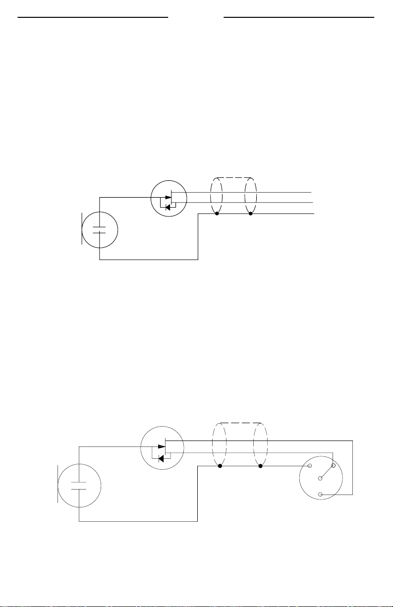
USING THE BETA 53 WITH OTHER BODYPACK TRANSMITTERS
If connecting the microphone to anything OTHER than a Shure wireless bodypack,
make sure it provides a regulated +5 Vdc source (130
mA minimum) to the red con-
ductor, as shown in Figure 1.
CONDENSER
CARTRIDGE
IMPEDANCE
CONVERTER
G
D+
S
RED
BLK
SHIELD
+5 Vdc (130 mA min.)
Audio Out
MICROPHONE WIRING DIAGRAM
FIGURE 1
USING THE BETA 53 WITH THE TA4F CONNECTOR
The following diagram shows how the Beta 53 is wired to the TA4F connector.
IMPEDANCE
CONVERTER
CONDENSER
CARTRIDGE
G
D
S
RED
BLK
SHIELD
+5 Vdc
Audio Out
1
4
2
3
TA4F CONNECTOR WIRING DIAGRAM
FIGURE 2
4
TA4F (solder side view)
Page 4

MICROPHONE PARTS
ENGLISH
Å
Ä
Æ
À Microphone Cartridge
Á Microphone Boom
À
Á
Ã
Â
 Boom Clip (rotates as shown)
à Cable
Ä Wireframe
Å Strain relief clips
Æ Earforms
WBH53 HEADWORN MICROPHONE PARTS
FIGURE 3
REVERSIBLE AND ADJUSTABLE BOOM
The Beta 53 boom can be placed on either side of the wireframe. Snap the boom
into the boom clip, which can be rotated as shown in Figure 3. The boom can also
slide forward and backward in the boom clip to adjust the microphone-to-mouth distance. CAUTION! Do not attempt to bend the boom itself. Adjust the boom by rolling
it closer to or further away from the mouth.
WEARING THE WBH53
Place the wireframe around your head so the earforms go over the ears from behind
and the wireframe lays horizontally across the base of the skull (see Figure 4).
WEARING THE BETA 53
FIGURE 4
5
Page 5

ENGLISH
POSITIONING THE MICROPHONE
For best performance, the Beta 53 microphone should be placed at the corner of the
mouth, and as close to the mouth as possible without touching any skin or facial hair
(see Figure 5). If necessary, the boom can be “rolled away” from the mouth to avoid
contact with facial hair (see Figures 6 and 7).
CORRECT POSITIONING OF THE MICROPHONE
FIGURE 5
INCORRECT POSITIONING OF THE MICROPHONE
FIGURE 6
“ROLLING” THE MICROPHONE BOOM
FIGURE 7
6
Page 6

ENGLISH
SPECIFICATIONS
(measured with a standard test circuit, see Figure 9 on page 33).
+20
+10
0
–10
–20
RELATIVE RESPONSE IN dB
–40
500 1,000 2,000 5,000 10,000 20,00050 100 20020
FREQUENCY IN Hz
High Boost Equalization Cap
Mild Boost Equalization Cap
TYPICAL FREQUENCY RESPONSE
FIGURE 8
Type
Condenser (electret bias)
Frequency Response
20 to 20,000 Hz (see Figure 8)
Polar Pattern
Omnidirectional
Recommended Minimum
Input Impedance
20 kW
Output Level
Open Circuit Voltage
-54 dBV/Pa
1 Pascal = 94 dB SPL
Maximum Sound Pressure Level
142 dB at 1% THD/1 kW load
Dynamic Range
103 dB
Output Noise
(equivalent SPL, A-weighted)
39 dB typical; 42 dB maximum
Signal-to-Noise Ratio
55 dB at 94 dB SPL
Current Drain
60–130 mA
Polarity
Positive pressure on the diaphragm
produces a positive voltage at pin 3
relative to pin 1 at the output connector of the microphone.
Power Requirements
+5 Vdc on pin 2, return on pin 1
(ground)
Environmental Conditions
Operating Temperatures:
_
_
-18
to 57
Storage Temperatures:
_
-29
to 74
C (0
_
C (-20
_
to 135
_
to 165
_
F)
_
F)
Humidity: 0 to 95%
Cable
1.5 m (5 ft), small-diameter, shielded, with mini 4–pin connector
(TA4F), or 3 m (10 ft.) small-diameter, shielded, no connector.
Net Weight
35.35 g (1.25 oz.) with cable and
TA4F connector.
7
Page 7

ENGLISH
Certification
Eligible to bear CE marking. Conforms to European EMC directive 89/336/EEC.
Meets applicable tests and performance criteria in European EMC Standard EN
55103 (1996) parts 1 and 2, for residential (E1) and light industrial (E2) environments. Meets applicable test and performance criteria in European wireless microphone EMC standard ETS 300445 (1996) as an “ancilliary device.”
FURNISHED ACCESSORIES
Foam windscreens (2 pcs.), black or beige
High Boost Equalization Caps (2 pcs.), black or beige
Mild Boost Equalization Caps (2 pcs.), black or beige
Swiveling Lapel Clip (1 pc.), black or beige
Plastic Carrying Case, black
OPTIONAL ACCESSORIES
In-line Preamplifier RPM626. . . . . . . . . . . . . . . . . . . . . . . . . . . . . . . . . . . . . . . . . . . . . .
Phantom Power Supply (requires the use of an in-line preamplifier) PS1A. . . . . . .
Battery Operated Preamplifier MX1BP. . . . . . . . . . . . . . . . . . . . . . . . . . . . . . . . . . . . . .
REPLACEMENT PARTS
High Boost Equalization Cap (5 pcs.)
Black RPM208. . . . . . . . . . . . . . . . . . . . . . . . . . . . . . . . . . . . . . . . . . . . . . . . . . . . . . .
Beige RPM212. . . . . . . . . . . . . . . . . . . . . . . . . . . . . . . . . . . . . . . . . . . . . . . . . . . . . .
Mild Boost Equalization Cap (5 pcs.)
Black RPM220. . . . . . . . . . . . . . . . . . . . . . . . . . . . . . . . . . . . . . . . . . . . . . . . . . . . . . .
Beige RPM214. . . . . . . . . . . . . . . . . . . . . . . . . . . . . . . . . . . . . . . . . . . . . . . . . . . . . .
Swiveling Lapel Clip (5 pcs.)
Black RPM510. . . . . . . . . . . . . . . . . . . . . . . . . . . . . . . . . . . . . . . . . . . . . . . . . . . . . . .
Beige RPM512. . . . . . . . . . . . . . . . . . . . . . . . . . . . . . . . . . . . . . . . . . . . . . . . . . . . . .
Boom Holder and Logo Pad (2 pcs.)
Black RPM570. . . . . . . . . . . . . . . . . . . . . . . . . . . . . . . . . . . . . . . . . . . . . . . . . . . . . . .
Beige RPM580. . . . . . . . . . . . . . . . . . . . . . . . . . . . . . . . . . . . . . . . . . . . . . . . . . . . . .
Foam Windscreens (5 pcs.)
Black RPM304. . . . . . . . . . . . . . . . . . . . . . . . . . . . . . . . . . . . . . . . . . . . . . . . . . . . . . .
Beige RPM306. . . . . . . . . . . . . . . . . . . . . . . . . . . . . . . . . . . . . . . . . . . . . . . . . . . . . .
Plastic Carrying Case for Beta 53, black 95A2180. . . . . . . . . . . . . . . . . . . . . . . . . . . .
Replacement Headband for Beta 53
Black RPM550. . . . . . . . . . . . . . . . . . . . . . . . . . . . . . . . . . . . . . . . . . . . . . . . . . . . . . .
Beige RPM560. . . . . . . . . . . . . . . . . . . . . . . . . . . . . . . . . . . . . . . . . . . . . . . . . . . . . .
Mini 4–pin Connector (TA4F) WA330. . . . . . . . . . . . . . . . . . . . . . . . . . . . . . . . . . . . . .
Microphone and Boom Assembly for Beta 53, Mini 4–pin Connector (TA4F)
Black RPM132. . . . . . . . . . . . . . . . . . . . . . . . . . . . . . . . . . . . . . . . . . . . . . . . . . . . . . . . . .
Beige RPM134. . . . . . . . . . . . . . . . . . . . . . . . . . . . . . . . . . . . . . . . . . . . . . . . . . . . . . . . . .
Microphone and Boom Assembly for Beta 53, Tinned Leads (No Connector)
Black RPM136. . . . . . . . . . . . . . . . . . . . . . . . . . . . . . . . . . . . . . . . . . . . . . . . . . . . . . . . . .
Beige RPM138. . . . . . . . . . . . . . . . . . . . . . . . . . . . . . . . . . . . . . . . . . . . . . . . . . . . . . . . . .
8
Page 8

20 k
1.0 uf
3
1
4
2
5 Vdc
100 k
STANDARD TEST CIRCUIT S CIRCUIT D’ESSAI S PRUFSCHALTUNG S
CIRCUITO DE PRUEBA S CIRCUITO DI PROVA
FIGURE 9 S FIGURE 9 S ABBILDUNG 9 S FIGURA 9 S FIGURA 9
33
Page 9

Patent Notice: Patent Des. 451,902
SHURE Incorporated Web Address: http://www.shure.com
222 Hartrey Avenue, Evanston, IL 60202–3696, U.S.A.
Phone: 847-866–2200 Fax: 847-866-2279
In Europe, Phone: 49-7131-72140 Fax: 49-7131-721414
In Asia, Phone: 852-2893-4290 Fax: 852-2893-4055
Elsewhere, Phone: 847-866–2200 Fax: 847-866-2585
 Loading...