

Page 1
Shure SLX Wireless
SLX Wireless System
SLX sans fil de Shure
Sistema inalámbrico Shure SLX
Shure SLX Sem Fio
©2012 Shure Incorporated
27A15631 (Rev. 2)
Printed in U.S.A.
Page 2
12–18 V
INSTRUMENT OUT
INSTRUMENT OUT
160 mA
BALANCED
LOW Z
POWER
ANTENNA B
SHURE INCORPORATED
NILES, IL 60714
UNBALANCED
SLX4 RECEIVER
HIGH Z
N108
IC: 616A–SLX4
MIC OUT INSTRUMENT OUTVOLUME ANTENNA A
Page 3
Page 4
SLX
mute select
Shure SLX Wireless
Smart, Hard-working Wireless
Congratulations! Welcome to Shure SLX Wireless. Your new system is rugged, reliable, easy to set up and
operate, and produces outstanding audio clarity. Whether you’re a vocalist, guitarist, or instrumentalist, your
SLX Wireless system will show you how easy wireless can be, and how good wireless can sound.
Welcome to the world of SLX: smart, hard-working wireless.
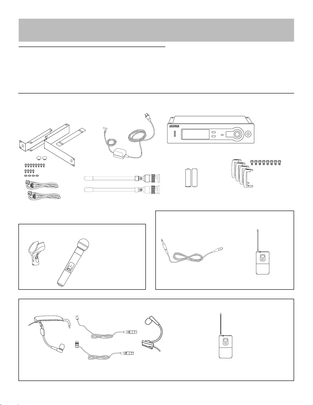
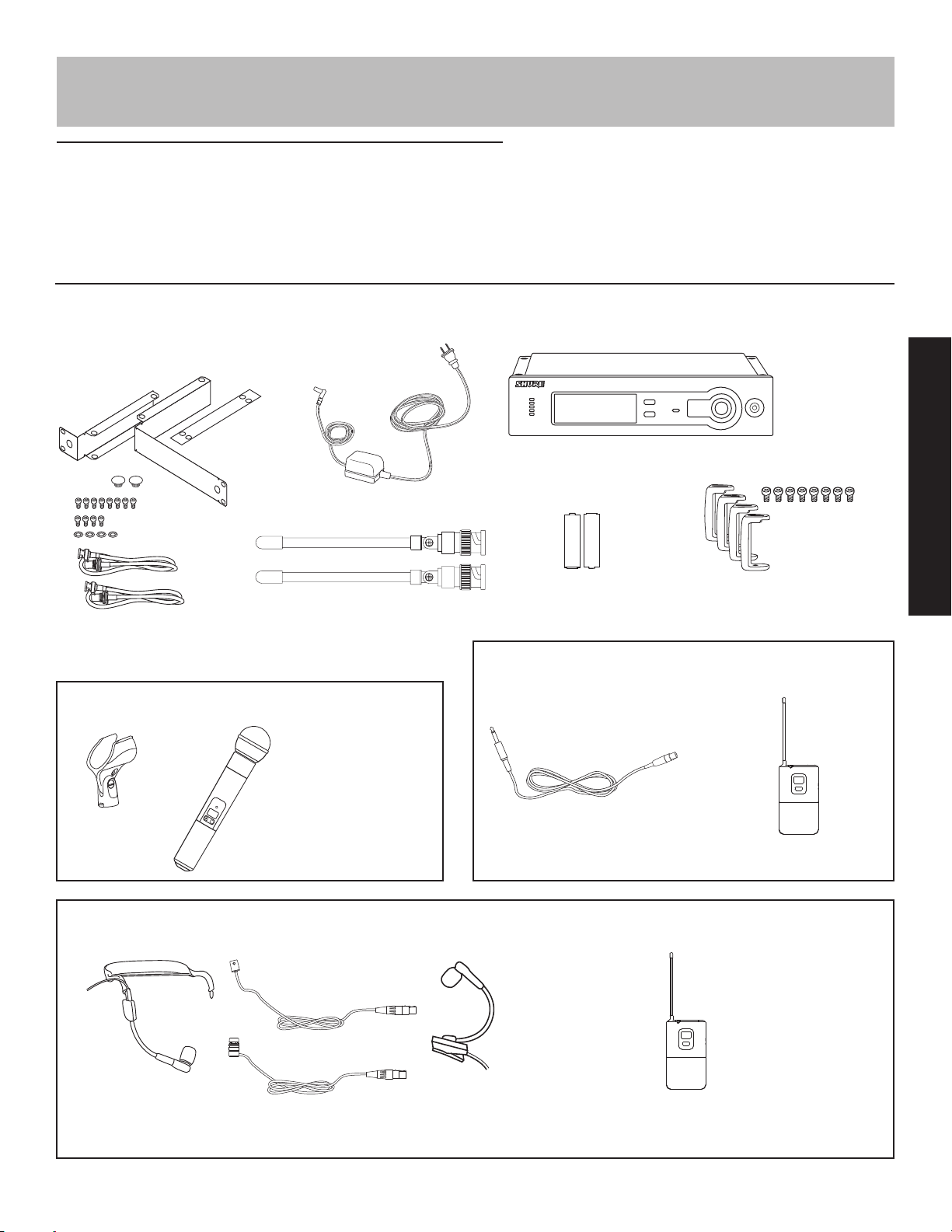
System Components
All systems include:
Power supply
+
SLX4 receiver
-
2 1/4 Wave Antennas
Rack mount supplies
Vocalist system includes:
Microphone Head (choice of
SM58®, SM86, Beta 58A®, Beta
87A™, or Beta 87C™)
Microphone clip
SLX2 handheld transmitter
Lavalier, Headworn, and Instrument systems include:
WL93
-
+
2 AA batteries (4 in combo systems)
Guitar system includes:
1/4” to mini 4-pin guitar cable
Protective bumpers with 8 screws
SLX1 bodypack transmitter
WH30
WL184/
WL185
Microphone (choice of WL93 , WL184 or WL185 , WH30 , or Beta 98H/C™ )
Beta 98H/C™
SLX1 bodypack transmitter
4
Page 5
ANTENNA B
POWER
MIC OUT LINE OUT VOLUME ANTENNA A
BALANCED
LOW Z
UNBALANCED
HIGH Z
12–18 V
170 mA
SHURE INCORPORATED
NILES, IL 60714
SLX4 RECEIVER
IC: 616A–SLX4
N108
• 1 x UA844
• 1 x UA844
ANTENNA B
POWER
MIC OUT LINE OUT VOLUME ANTENNA A
BALANCED
LOW Z
UNBALANCED
HIGH Z
12–18 V
170 mA
SHURE INCORPORATED
NILES, IL 60714
SLX4 RECEIVER
IC: 616A–SLX4
N108
ANTENNA B
POWER
MIC OUT LINE OUT VOLUME ANTENNA A
BALANCED
LOW Z
UNBALANCED
HIGH Z
12–18 V
170 mA
SHURE INCORPORATED
NILES, IL 60714
SLX4 RECEIVER
IC: 616A–SLX4
N108
ANTENNA B
POWER
MIC OUT LINE OUT VOLUME ANTENNA A
BALANCED
LOW Z
UNBALANCED
HIGH Z
12–18 V
170 mA
SHURE INCORPORATED
NILES, IL 60714
SLX4 RECEIVER
IC: 616A–SLX4
N108
• 1 x UA221
ANTENNA B
POWER
MIC OUT LINE OUT VOLUME ANTENNA A
BALANCED
LOW Z
UNBALANCED
HIGH Z
12–18 V
170 mA
SHURE INCORPORATED
NILES, IL 60714
SLX4 RECEIVER
IC: 616A–SLX4
N108
ANTENNA B
POWER
MIC OUT LINE OUT VOLUME ANTENNA A
BALANCED
LOW Z
UNBALANCED
HIGH Z
12–18 V
170 mA
SHURE INCORPORATED
NILES, IL 60714
SLX4 RECEIVER
IC: 616A–SLX4
N108
• 1 x UA221
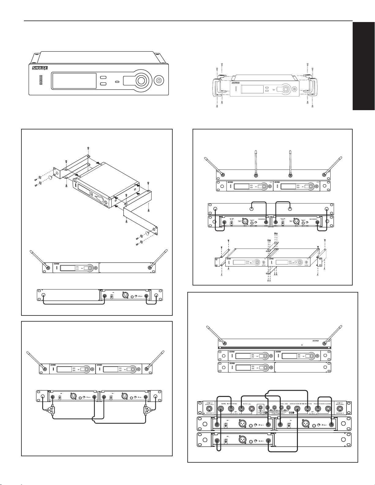
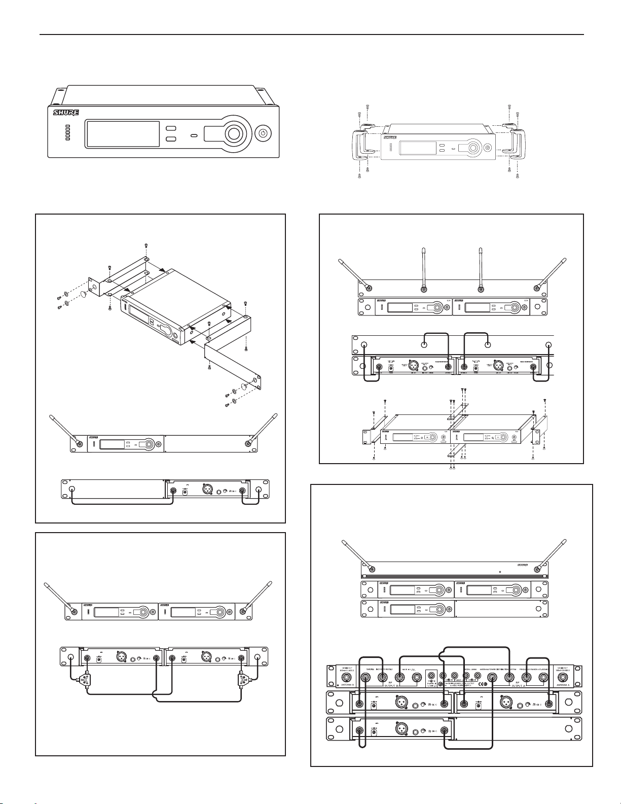
SLX4 Receiver
Rack-Mounting SLX Receivers
ENGLISH
Adding protective bumpers
Recommended if receiver is not rack mounted. Use supplied screws.
One Receiver
• All accessories supplied
Two Receivers
• Required Accessories: 1 x UA440
UA440
SLX4
12–18 V
170 mA
BALANCED
LOW Z
POWER
ANTENNA B
SHURE INCORPORATED
NILES, IL 60714
UNBALANCED
SLX4 RECEIVER
HIGH Z
N108
IC: 616A–SLX4
MIC OUT LINE OUT VOLUME ANTENNA A
Three or Four Receivers
• Required Accessories: 1 x UA844
Two Receivers with UA221 Antenna Splitter/Combiner Kit
• Required Accessories: 1 x UA221
SLX4 SLX4
12–18 V
170 mA
BALANCED
LOW Z
POWER
ANTENNA B
SHURE INCORPORATED
NILES, IL 60714
UNBALANCED
SLX4 RECEIVER
HIGH Z
IC: 616A–SLX4
MIC OUT LINE OUT VOLUME ANTENNA A
12–18 V
170 mA
BALANCED
N108
LOW Z
POWER
ANTENNA B
SHURE INCORPORATED
NILES, IL 60714
UNBALANCED
SLX4 RECEIVER
HIGH Z
N108
IC: 616A–SLX4
MIC OUT LINE OUT VOLUME ANTENNA A
UA221
UA844
UHF ANTENNA / POWER DISTRIBUTION SYSTEM
SLX4 SLX4
SLX4
12–18 V
170 mA
BALANCED
LOW Z
POWER
ANTENNA B
12–18 V
170 mA
BALANCED
LOW Z
POWER
ANTENNA B
SHURE INCORPORATED
NILES, IL 60714
UNBALANCED
SLX4 RECEIVER
HIGH Z
N108
IC: 616A–SLX4
MIC OUT LINE OUT VOLUME ANTENNA A
SHURE INCORPORATED
NILES, IL 60714
UNBALANCED
SLX4 RECEIVER
HIGH Z
N108
IC: 616A–SLX4
MIC OUT LINE OUT VOLUME ANTENNA A
12–18 V
170 mA
POWER
ANTENNA B
UA844
POWER
UNBALANCED
BALANCED
HIGH Z
LOW Z
MIC OUT LINE OUT VOLUME ANTENNA A
SHURE INCORPORATED
NILES, IL 60714
SLX4 RECEIVER
IC: 616A–SLX4
N108
5
Page 6
ANTENNA A
SHURE INCORPORATED
NILES, IL 60714
SLX4 RECEIVER
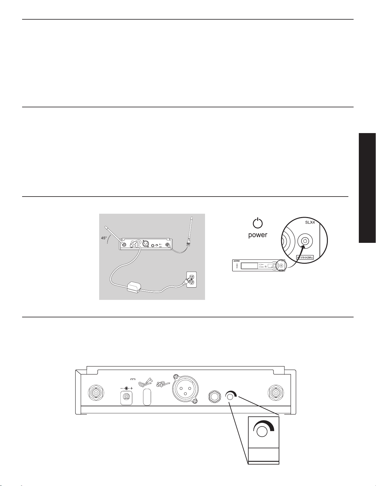
Single System Setup
Follow these steps when using a single SLX system:
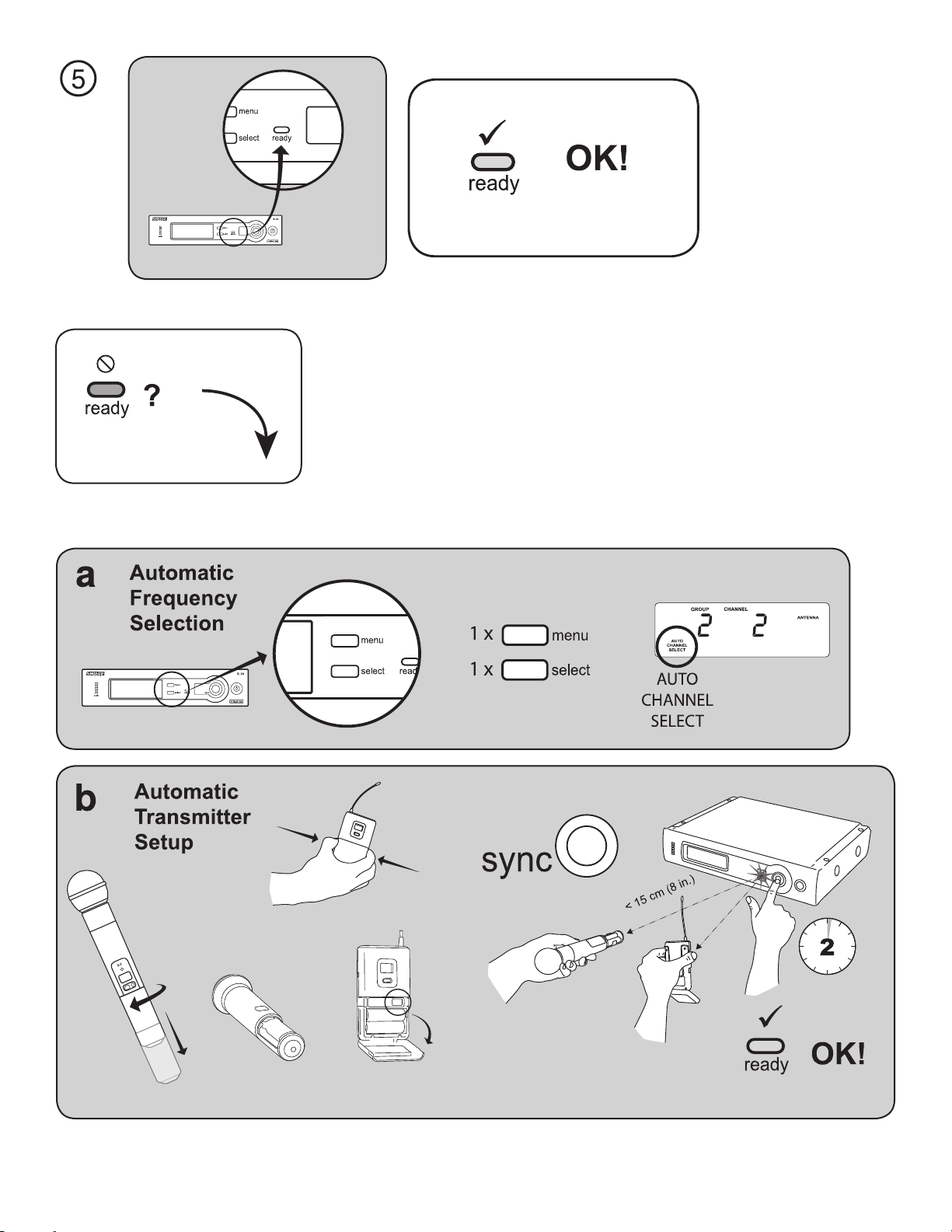
Automatic Frequency Selection
Scans for an available channel and sets the receiver to that channel.
Automatic Transmitter Setup
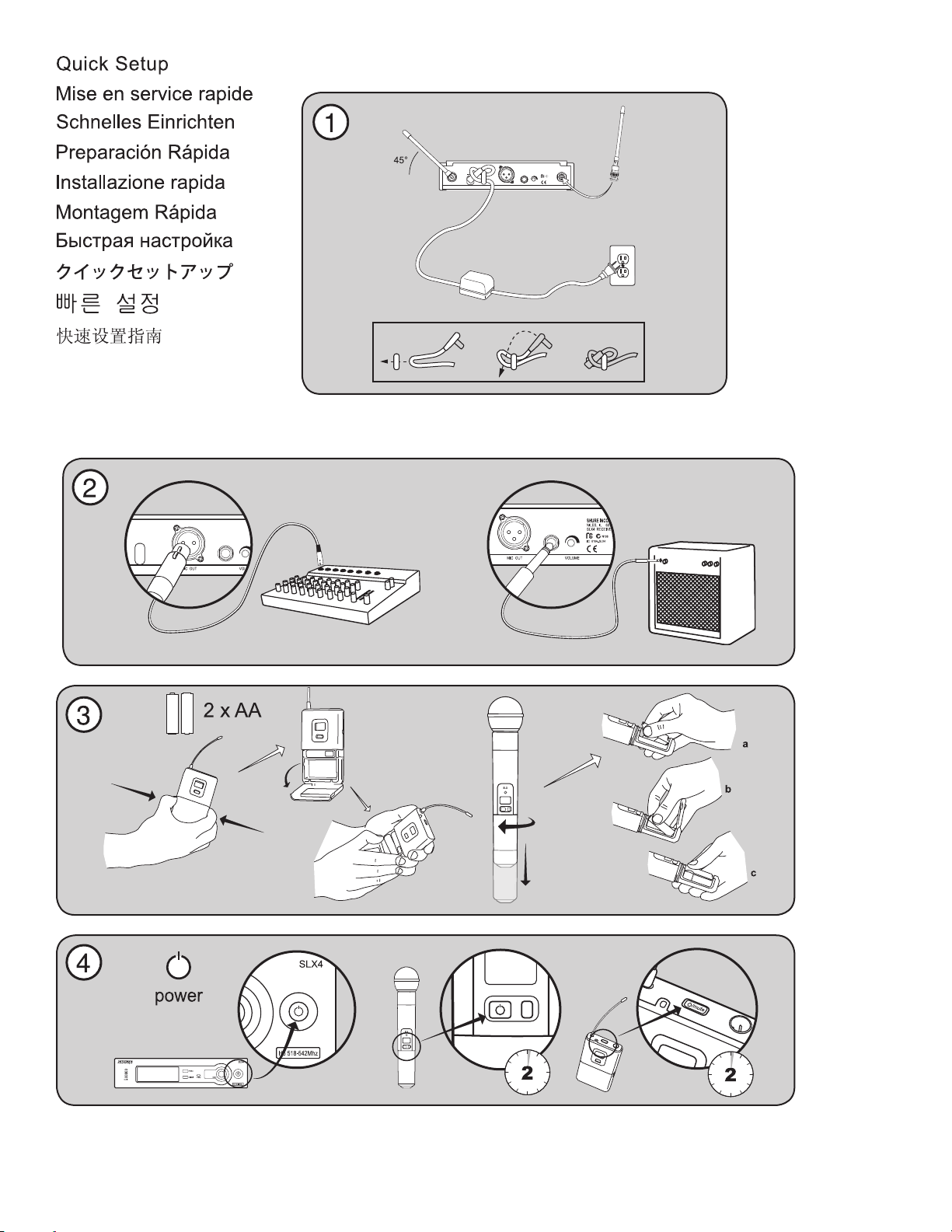
1. Turn On the transmitter.
2. Open the transmitter battery compartment to display the infrared (IR) port
3. With the IR port exposed to the receiver, press sync.
4. Hold the sync button until the red light stops flashing on both receiver and transmitter.
5. When the receiver ready light glows, the system is ready for use.
6. Close the transmitter battery compartment.
Multiple System Setup
Follow these steps when using multiple SLX systems in a single installation:
1. Turn all receivers on and all transmitters off.
2. Set all receivers to the same frequency group
3. Perform Automatic Frequency Selection from the Single System Setup section above.
4. Turn on the first transmitter.
5. Perform Automatic Transmitter Setup from the Single System Setup section above.
6. Repeat for each system.
Be sure that only one transmitter’s IR port is exposed when synchronizing a system.
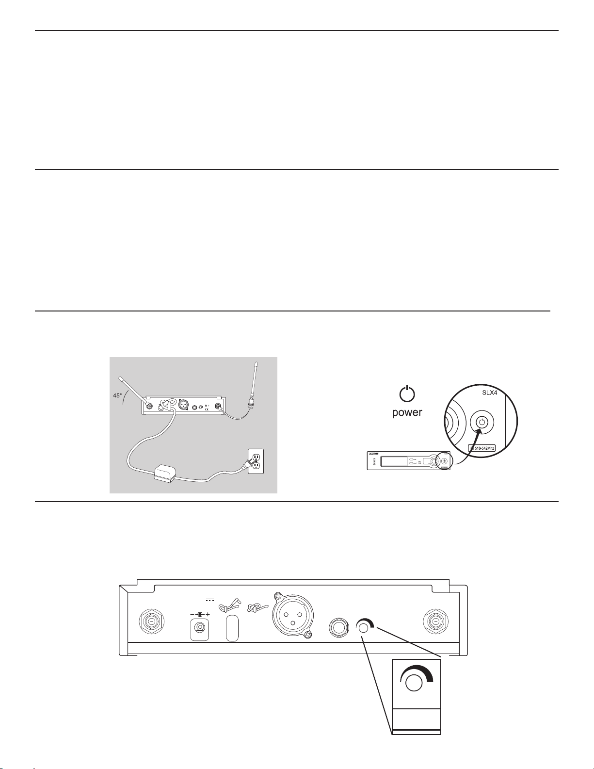
On/Off switch
Tap to turn on, hold to turn off.
12–18 V
160 mA
BALANCED
LOW Z
POWER
ANTENNA B
SHURE INCORPORATED
NILES, IL 60714
UNBALANCED
SLX4 RECEIVER
HIGH Z
N108
IC: 616A–SLX4
MIC OUT INSTRUMENT OUTVOLUME ANTENNA A
Receiver Volume Control
The volume control dial should generally be left in the clockwise position. Turning the dial
counter-clockwise decreases receiver output level.
If adjustments are necessary, use a small screwdriver to turn the dial.
12–18 V
160 mA
SHURE INCORPORATED
NILES, IL 60714
SLX4 RECEIVER
6
ANTENNA B
POWER
MIC OUT INSTRUMENT OUT VOLUME ANTENNA A
VOLUME
Page 7
888.888
GROUP
CHANNEL
AUTO
CHANNEL
SELECT
GROUP
SELECT
MANUAL
CHANNEL
SELECT
DISPLAY
FREQUENCY
SELECT
EXIT
MASTER
LIST
MASTER LIST
MHz
LOW BATT
888.888
GROUP
CHANNEL
AUTO
CHANNEL
SELECT
GROUP
SELECT
MANUAL
CHANNEL
SELECT
DISPLAY
FREQUENCY
SELECT
EXIT
MASTER
LIST
ANTENNA
A
B
MASTER LIST
MHz
888.888
GROUP
CHANNEL
AUTO
CHANNEL
SELECT
MANUAL
CHANNEL
SELECT
DISPLAY
FREQUENCY
SELECT
EXIT
MASTER
LIST
ANTENNA
A
B
MASTER LIST
MHz
LOW BATT
888.888
GROUP
CHANNEL
AUTO
CHANNEL
SELECT
GROUP
SELECT
MANUAL
CHANNEL
SELECT
DISPLAY
FREQUENCY
SELECT
EXIT
MASTER
LIST
ANTENNA
A
B
MASTER LIST
MHz
LOW BATT
888.888
GROUP
CHANNEL
AUTO
CHANNEL
SELECT
GROUP
SELECT
MANUAL
CHANNEL
SELECT
EXIT
MASTER
LIST
ANTENNA
A
B
MASTER LIST
MHz
LOW BATT
888.888
GROUP
CHANNEL
AUTO
CHANNEL
SELECT
GROUP
SELECT
MANUAL
CHANNEL
SELECT
DISPLAY
FREQUENCY
SELECT
EXIT
MASTER
LIST
ANTENNA
A
B
MASTER LIST
MHz
LOW BATT
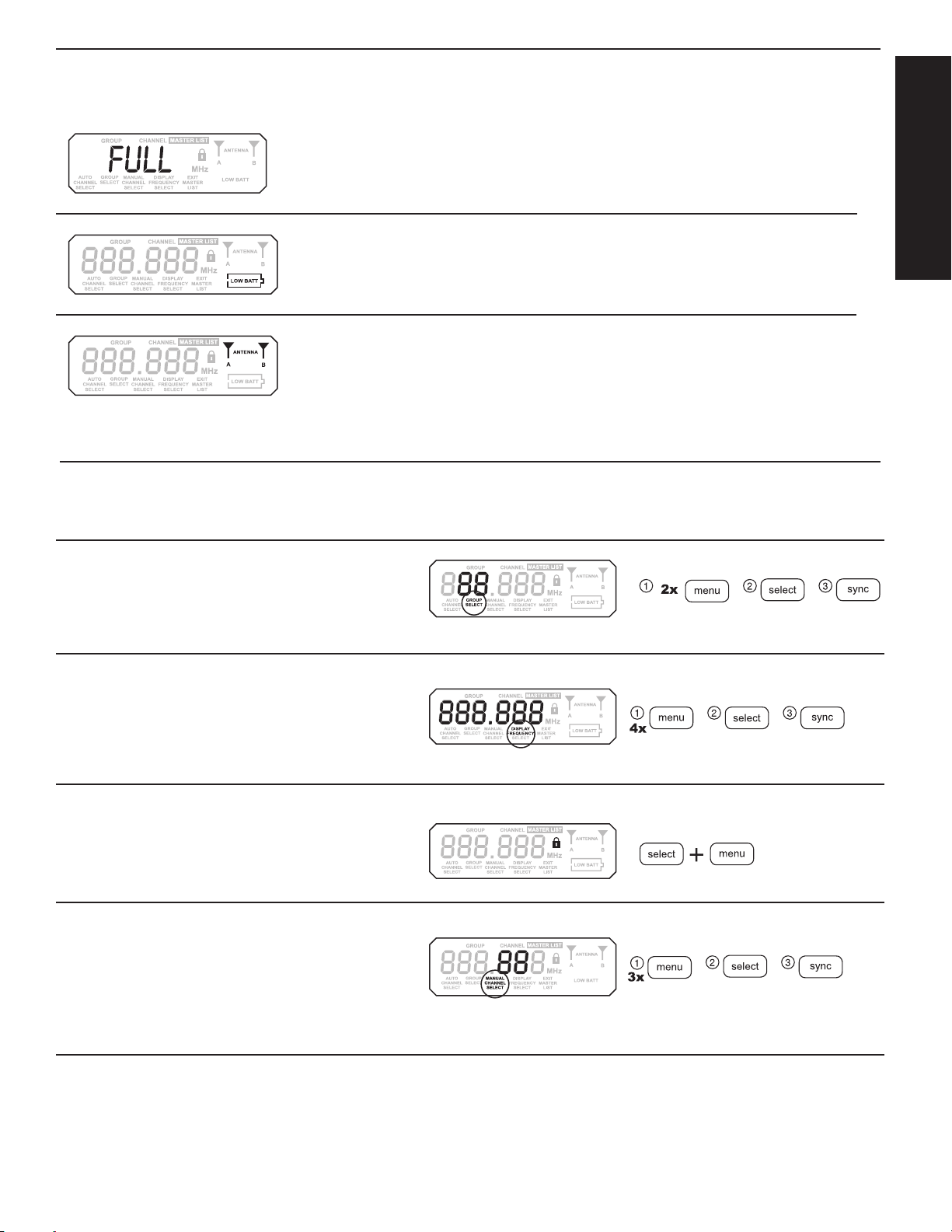
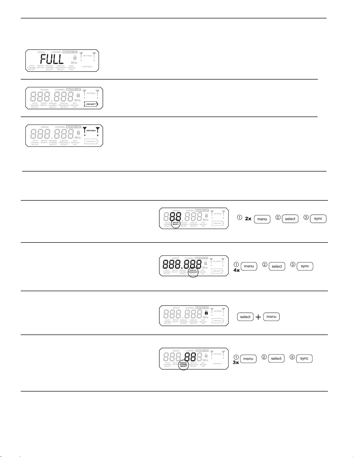
SLX4 LCD
Full Group Warning
The FULL warning indicates that all available channels in the currently selected group are in
use. When this occurs, reprogram all systems to an alternate group.
Press either the menu or select button to exit the warning screen.
Transmitter Battery Status
Indicates a low transmitter battery charge.
Antenna Status
Indicates RF activity. Only one antenna is active at any one time.
SLX4 Receiver Programming
Any option displayed on screen will generally “time out” after five seconds.
ENGLISH
Group Selection
Allows manual selection of a frequency group. Pressing select increases the group
number by one. When the correct frequency is displayed, either wait five seconds
for the screen to time out, or press sync. For best results when operating multiple
systems, set all systems to a single group; then set each system to a unique channel
within that group.
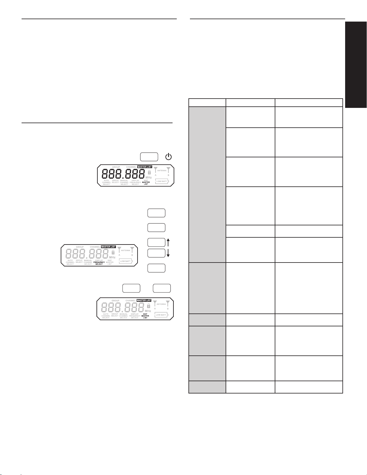
Display Frequency
Displays the current frequency in MHz for approximately 5 seconds. Press and
hold to increase display length.
Lock or Unlock Receiver Settings
Hold down the select key and press menu to lock or unlock the receiver. When
locked, the current receiver settings cannot be changed.
Manual Channel Selection
Allows manual selection of a frequency channel. Pressing select increases the
channel number by one. When the correct frequency is displayed, either wait
five seconds for the screen to time out, or press sync.
GROUP
SELECT
MANUAL
CHANNEL
SELECT
DISPLAY
FREQUENCY
7
Page 8
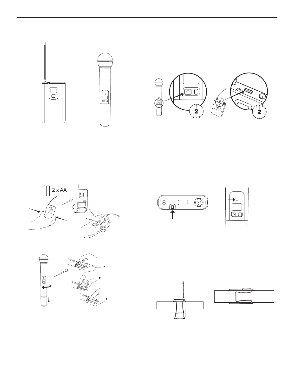
SLX1 & SLX2 Transmitters
SLX2
SLX
SLX1
Changing Batteries
• Expected life for an Alkaline battery is approximately 8 hours.
• When the transmitter light glows red, the batteries should be changed immediately, as
shown on the left.
mute select
On-off / mute switch
Press and hold to turn on or off. Press and release to mute or unmute.
To avoid accidentally muting the microphone during a performance, lock the front panel while the
microphone is in use.
Power / Infrared (IR) / Mute indicator
Green: ready
Amber: mute on
Flashing red: IR transmission in process
Glowing red: battery power low
Pulsing red: battery dead (transmitter cannot be turned on until batteries are changed)
SLX
mute select
Wearing the Bodypack Transmitter
Clip the transmitter to a belt or slide a guitar strap through the transmitter clip as shown.
For best results, slide the transmitter until the belt is pressed against the base of the clip.
8
Page 9
i8 i8
Incompatible
CHANNEL
i8 i8
MASTER LIST
Incompatible
GROUP
i8 i8
Incompatible
GROUP
CHANNEL
i8 i8
GROUP
CHANNEL
i8 i8
GROUP
CHANNEL
i8 i8
Incompatible
GROUP
CHANNEL
If the receiver LED indicates the input volume is
overloading the receiver, try switching the gain to
a lower setting.
SLX2
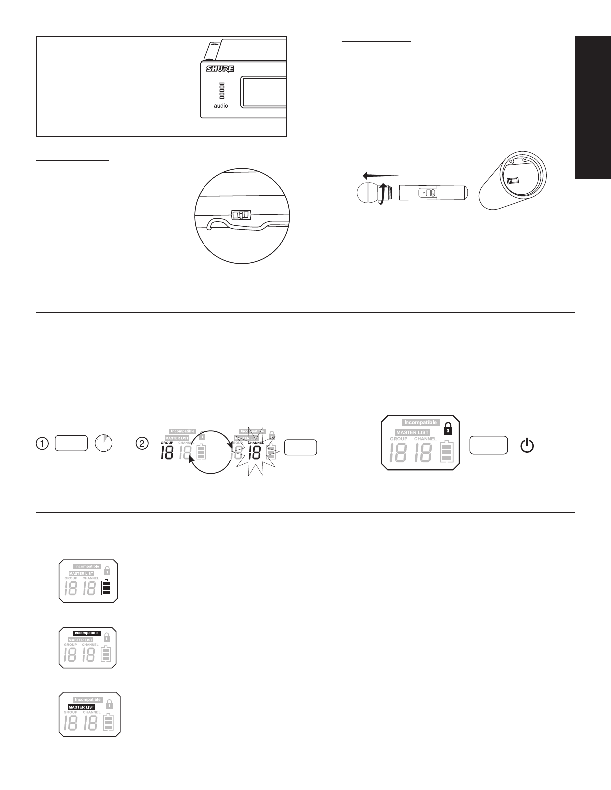
Adjusting Gain
Access the gain adjustment switch by unscrewing the head of
the microphone.
Two gain settings are available on the SLX2. Choose a setting
appropriate for vocal volume and for the performing environment. Use the tip of a pen or a small screwdriver to move the
switch.
• 0dB: For quiet to normal vocal performance.
• –10dB: For loud vocal performance.
ENGLISH
SLX1
Adjusting Gain
Three gain settings are available on the SLX1. Choose
the appropriate setting for your instrument.
• mic: Microphone (higher amplification)
• 0: Guitar with passive pickups (medium amplification)
• –10: Guitar with active pickups (lower amplification)
SLX1 and SLX2 Transmitter Programming
Manually Select a Group and/or Channel
1. Press and hold the select button until the GROUP and CHANNEL displays alternate.
2. To change the group setting, release the select button while GROUP is displayed. While GROUP is
flashing, pressing select increases the group setting.
3. To change the channel setting, release the select button while CHANNEL is displayed. While CHANNEL
is flashing, pressing select increases the channel setting.
select
5
-10 0 mic
select
BIAS
AUDIO
0dB
select
-10dB
+
SLX
mute select
Lock or Unlock Transmitter Settings
Press the mute and select buttons simultaneously to lock or unlock the transmitter settings. When locked, the current settings
cannot be changed manually. Locking the transmitter does
not disable infrared synchronization.
SLX1 & SLX2 LCD
Battery Status
Indicates charge remaining in transmitter batteries.
INCOMPATIBLE Frequency Warning
The INCOMPATIBLE warning indicates that the receiver and transmitter
are set to incompatible frequency bands. Contact your Shure retailer for
assistance.
Master List Indicator
Indicates that a master list frequency is currently in use. No group or
channel information is displayed.
Note: the transmitter cannot be used to change master list settings.
9
Page 10
SLX
Working Range
Line of Sight
Audio Frequency Response
Total Harmonic Distortion
Ref. ±38 kHz deviation with 1 kHz
tone
Dynamic Range
Operating Temperature Range
Transmitter Audio Polarity
100 m (300 ft)
Note: Actual range depends on RF signal absorption,
reflection and interference.
45–15000 Hz
Note: Dependent on microphone type
<0.5%, typical
>100 dB, A-weighted
-18°C (0°F) to +50°C (122°F)
Note: Battery characteristics may limit this range.
Positive pressure on microphone diaphragm (or
positive voltage applied to tip of WA302 phone plug)
produces positive voltage on pin 2 (with respect to
pin 3 of low-impedance output) and the tip of the high
impedance 1/4-inch output.
SLX1
Audio Input Level gain position
mic:
−10dBVmaximum
0dB:
+10dBVmaximum
–10dB:
+20dBVmaximum
Gain Adjustment Range
Input Impedance
RF Output Power
Pin Assignments
TA4M
Dimensions
Weight
Housing
Power Requirements
Battery Life
30 dB
1MΩ
10–30 mW
varies by region
1:
ground (cable shield)
2:
+5VBias
3:
audio
4:
Tied through active load
to ground (On instrument adapter cable, pin
4 floats)
108mm x 64mm x 19mm (H x W x D)
81 g (3 oz.), without batteries
galvanized steel
2 "AA" size alkaline or rechargeable batteries
up to 8 hours (alkaline)
SLX2
Maximum Input Level at –10 dB gain
at 0 dB gain setting:
Gain Adjustment Range
RF Output Power
Dimensions
Weight
Housing
Power Requirements
Battery Life
10 dB
10–30 mW
varies by region
254mm X 51mm dia. (10 X 2in.)
290 g (10.2oz.) (without batteries)
Molded PC/ABS handle and battery cup
2 "AA" size alkaline or rechargeable batteries
up to 8 hours (alkaline)
setting:
+2dBV
–8dBV
SLX4
Dimensions
Weight
Housing
Sensitivity
Power Requirements
Configuration
Maximum Audio Output Level
Ref. ±38 kHz deviation with 1 kHz
tone
Impedance XLR connector:
Pin Assignments XLR connector:
Image Rejection
Volume Adjustment Range
42mm X 197mm X 134mm (H x W x D)
816 g (1 lb 13oz.)
galvanized steel
-105 dBm for 12 dB SINAD, typical
12–18VDC@150mA,suppliedbyexternal
power supply (tip positive)
Impedance balanced
XLR connector:
6.35 mm (1/4")
connector:
6.35 mm (1/4")
connector:
6.35 mm (1/4")
connector:
>70 dB, typical
0 dB to -25 dB
–13dBV(into600Ω
load)
–2dBV(into3kΩload)
200Ω
1kΩ
1=ground, 2=audio,
3=no audio
Tip=audio, Ring=no audio, Sleeve=ground
Frequency Range and Transmitter
Output Level
Band Range Output Power
G4 470 to 494 MHz 30 mW
G4E 470 to 494 MHz 30 mW
G5 494 to 518 MHz 30 mW
G5E 494 to 518 MHz 30 mW
G8 494.200 to 509.825 MHz 30 mW
H5 518 to 542 MHz 30 mW
J3 572 to 596 MHz 30 mW
L4 638 to 662 MHz 30 mW
L4E 638 to 662 MHz 30 mW
P4 702 to 726 MHz 30 mW
R13 794 to 806 MHz 20 mW
R5 800 to 820 MHz 20 mW
X4 925 to 932 MHz 10 mW
S6 838 to 865 MHz 10 mW
S10 823 to 832 MHz 10 mW
JB 806 to 810 MHz 10 mW
R19 794 to 806 MHz 10 mW
Q4 740 to 752 MHz 10 mW
K3E 606 to 630 MHz 10 mW
NOTE:
This Radio equipment is intended for use in musical professional entertainment
and similar applications.
This Radio apparatus may be capable of operating on some frequencies not
authorized in your region. Please contact your national authority to obtain information on authorized frequencies and RF power levels for wireless microphone
products.
10
Page 11
888.888
GROUP
CHANNEL
AUTO
CHANNEL
SELECT
GROUP
SELECT
MANUAL
CHANNEL
SELECT
DISPLAY
FREQUENCY
SELECT
ANTENNA
A
B
MASTER LIST
MHz
LOW BATT
888.888
GROUP
CHANNEL
AUTO
CHANNEL
SELECT
GROUP
SELECT
MANUAL
CHANNEL
SELECT
DISPLAY
FREQUENCY
SELECT
EXIT
MASTER
LIST
ANTENNA
A
B
MASTER LIST
MHz
LOW BATT
Frequency Band Selection
Most countries closely regulate the radio frequencies used in the transmission of wireless information. These regulations state which devices can use which frequencies, and help to limit the
amount of RF (radio frequency) interference in all wireless communications.
To be flexible enough to operate worldwide, SLX receivers are available in a number of models,
each with a unique frequency range. Each frequency range, or band, spans up to 24 MHz of the
wireless broadcast spectrum.
To facilitate system setup and protect against RF interference, each system comes with multiple
predefined frequency groups and channels.
When using a single SLX system, the operating frequency will generally not have to be changed.
In an installation with multiple receiver/transmitter systems, each system must operate on a separate channel. The group and channel system provides an optimum frequency spread when using
multiple systems.
Within a single frequency band, up to 12 individual transmitter/receiver systems may be used in
a single installation. In regions where additional frequency bands are available, it is possible to
operate up to 20 systems simultaneously. Check with your local Shure retailer for information on
which bands are available in your area.
The Master Frequency List
Using the Master List
The “Master List” of frequencies should be
accessed only by experienced users in situations which call for precise frequency selection. The “Master List” is a comprehensive
index of all available frequencies in 25 kHz
increments. (125 kHz increments in the JB
band.)
To access the Master List, hold down the
menu button while powering on the SLX
receiver.
Select Frequencies in the Master List
While FREQUENCY SELECT is flashing, the select button scrolls
down through all available frequencies; the menu button scrolls up.
Press and release to change the frequency in 25 kHz increments;
press and hold to scroll quickly.
When the correct frequency is displayed, either wait five seconds for
the screen to time out, or press sync.
Exit the Master List
To exit the Master List and return to normal system operations, press menu, then select.
2x
menu select
menu
+
menu
select
select
menu
sync
Tips for Improving System
Performance
• Maintain a line of sight between transmitter and antenna
• Avoid placing the receiver near metal surfaces or any digital equipment (CD
players, computers, etc.)
• Secure the AC adapter cable to the receiver using the cable retainer loop
• If rack-mounting the receiver, front-mount the antennas
Issue Indicator Status Solution
No sound or faint
sound
Distortion or
unwanted noise
bursts
Distortion level increases gradually
Sound level different from cabled
guitar or microphone, or when
using different
guitars
FULL warning displays on receiver
Cannot turn transmitter off
Transmitter power light off •Turn transmitter on
Receiver LCD off •Make sure AC adapter is securely
Receiver display indicates
antenna activity
Receiver display indicates
no antenna activity; transmitter and receiver power
lights glowing
Transmitter power light
glowing or flashing red
INCOMPATIBLE warning
on transmitter
Receiver display indicates
antenna activity
Transmitter power light
glowing or flashing red
Transmitter light flashing red
•Make sure the +/- indicators on battery match the transmitter terminals
•Insert a fresh battery
plugged into electrical outlet and into
DC input connector on rear panel of
receiver
•Make sure AC electrical outlet works
and is supplying proper voltage
•Press mute switch on transmitter
•Turn up receiver volume control
•Increase transmitter gain switch
setting
•Check cable connection between
receiver and amplifier or mixer
•Extend receiver antennas vertically
•Move receiver away from metal
objects
•Check for line of sight between transmitter and receiver
•Move transmitter closer to receiver
•Check that receiver and transmitter
are using the same frequency
Replace transmitter batteries
The INCOMPATIBLE warning indicates that the receiver and transmitter
are set to incompatible frequency
bands. Contact your Shure retailer for
assistance.
•Remove nearby sources of RF
interference (CD players, computers, digital effects, in-ear monitor
systems, etc.)
•Change receiver and transmitter to a
different frequency
•Reduce transmitter gain
•Replace transmitter battery
•If using multiple systems, increase
the frequency spread between
systems.
Replace transmitter batteries
Adjust transmitter gain and receiver
volume as necessary
The FULL warning indicates that all
available channels in the currently
selected group are in use. When this
occurs, reprogram all systems to an
alternate group.
Replace transmitter batteries
ENGLISH
11
Page 12
Accessories and Parts
Optional Accessories
Black Grille for BETA 58A RK323G
Black Grille for BETA 87A and BETA 87C RK324G
Carrying Case WA610
CERTIFICATION
SLX1, SLX2, SLX4
This Class B digital apparatus complies with Canadian ICES-003.
Cet appareil numérique de la classe B est conforme à la norme NMB-003 du Canada.
Meets requirements of EMC standards EN 300 422 Parts 1 and 2 and EN 301 489 Parts 1 and 9.
Meets essential requirements of European R&TTE Directive 99/5/EC, eligible to bear the CE mark.
Replacement Parts
Microphone Stand Adapter (SLX2) WA371
Zipper Bag (SLX1) 26A13
Zipper Bag (SLX2) 26A14
Short Rack Bar 53A8611
Long Rack Bar 53A8612
Link Bar 53B8443
Antenna extension cables (2) 95A9023
Protective Bumpers (SLX4 Receiver) (4) 90A8977
ACAdapter(120VAC,60Hz) PS21
ACAdapter(220VAC,50Hz) PS21AR
ACAdapter(230VAC,50/60Hz,Europlug) PS21E
ACAdapter(230VAC,50/60Hz) PS21UK
ACAdapter(100VAC,50/60Hz) PS21J
SM58® Cartridge with Grille (SLX2/SM58) RPW112
SM86 Cartridge with Grille (SLX2/SM86) RPW114
BETA 58A® Cartridge with Grille (SLX2/BETA 58) RPW118
BETA 87A Cartridge with Grille (SLX2/BETA 87A) RPW120
BETA 87C Cartridge with Grille (SLX2/BETA 87C™) RPW122
Matte Silver Grille for SM58® (SLX2/SM58) RK143G
Matte Silver Grille for SM86 (SLX2/SM86) RPM226
Matte Silver Grille for BETA 58A® (SLX2/BETA 58) RK265G
Matte Silver Grille for BETA 87A (SLX2/BETA 87A) RK312
Matte Silver Grille for BETA 87C (SLX2/BETA 87C™) RK312
Belt Clip 44A8030
1/4-Wave Antenna (470 - 752 MHz) UA400B
1/4-Wave Antenna (774 - 952 MHz) UA400
Antenna Combiners and Accessories
Antennas and receivers must be from the same band.
The supplied 1/4 wave antennas can be used when mounted directly to the UA844. If antennas
are remote mounted, 1/2 wave antennas must be used.
Antennas and cables are for use with UA844, and cannot be used with stand-alone SLX receivers
Passive Antenna/Splitter Combiner Kit
(recommended for 2 receivers)
25’ Antenna Cable UA825
50’ Antenna Cable UA850
1/2 Wave Antenna Remote Mount Kit UA505
100’Antenna Cable UA100
UHF Antenna Power Distribution Amplifier
(recommended for 3 or more receivers)
U.S.A. UA844US
Europe UA844E
UK UA844UK
H5 Band UA820H
J3 Band UA820F
L4 Band UA820L
P4, Q4 Bands UA820B
R13, R5, S6, JB Bands UA820A
UA221
1/2 wave antenna
SLX1, SLX2
Certified under FCC Part 74. (FCC ID: DD4SLX1, DD4SLX2). Certified by IC in Canada under
RSS-123 and RSS-102. (IC: 616A-SLX1, 616A-SLX1G5, 616A-SLX2, 616A-SLX2G5).
SLX4
Approved under the Declaration of Conformity (DoC) provision of FCC Part 15. Certified in
Canada by IC to RSS-123. (IC: 616A-SLX4, 616A-SLX4G5).
Operation of this device is subject to the following two conditions: (1) this device may not cause interference, and (2) this device must accept any interference, including interference that may cause
undesired operation of the device.
The CE Declaration of Conformity can be obtained from Shure Incorporated or any of its European
representatives. For contact information please visit www.shure.com
The CE Declaration of Conformity can be obtained from: www.shure.com/europe/compliance
Authorized European representative:
Shure Europe GmbH
Headquarters Europe, Middle East & Africa
Department: EMEA Approval
Jakob-Dieffenbacher-Str.12,
75031 Eppingen, Germany
Phone: +49-7262-92490
Fax: +49-7262-9249114
Email:EMEAsupport@shure.de
LICENSING INFORMATION
Licensing: A ministerial license to operate this equipment may be required in certain areas.
Consult your national authority for possible requirements. Changes or modifications not expressly
approved by Shure Incorporated could void your authority to operate the equipment. Licensing of
Shure wireless microphone equipment is the user’s responsibility, and licensability depends on the
user’s classification and application, and on the selected frequency. Shure strongly urges the user
to contact the appropriate telecommunications authority concerning proper licensing, and before
choosing and ordering frequencies.
Information to the user
This equipment has been tested and found to comply with the limits for a Class B digital device,
pursuant to Part 15 of the FCC Rules. These limits are designed to provide reasonable protection
against harmful interference in a residential installation. This equipment generates uses and can
radiate radio frequency energy and, if not installed and used in accordance with the instructions,
may cause harmful interference to radio communications. However, there is no guarantee that
interference will not occur in a particular installation. If this equipment does cause harmful interference to radio or television reception, which can be determined by turning the equipment off
and on, the user is encouraged to try to correct the interference by one or more of the following
measures:
• Reorient or relocate the receiving antenna.
• Increase the separation between the equipment and the receiver.
• Connect the equipment to an outlet on a circuit different from that to which the receiver is
connected.
• Consultthedealeroranexperiencedradio/TVtechnicianforhelp.
Note: EMC conformance testing is based on the use of supplied and recommended cable types.
The use of other cable types may degrade EMC performance.
Changes or modifications not expressly approved by the manufacturer could void the
user’s authority to operate the equipment.
WARNING: Dispose of properly. Check with local vendor for proper disposal of used battery and
electronics.
12
Page 13
SLX
mute select
SLX sans fil de Shure
Des systèmes sans fil intelligents et
performants
Félicitations ! Bienvenue dans le monde des systèmes SLX sans fil de Shure. Ce nouveau système est
robuste, fiable, facile à mettre en service et à utiliser et génère un son d’une clarté exceptionnelle. Que l’on
soit chanteur, guitariste ou instrumentiste, le système SLX sans fil est la preuve-même que l’audio sans fil
peut être simple comme bonjour, tout en produisant un son remarquable.
Bienvenue dans le monde de SLX : des systèmes sans fil intelligents et performants.
Composants des systèmes
Tous les systèmes comprennent :
Bloc d’alimentation
Récepteur SLX4
-
+
Français
Accessoires de montage en rack
Le système pour chanteur comprend :
Capsule de microphone (choix
entre SM58®, SM86, Beta 58A®,
Beta 87A™ ou Beta 87C™)
Pince de microphone
Émetteur à main SLX2
Les systèmes à micro-cravate, à microphone de casque et
d’instrument comprennent :
WL93
-
+
2 piles AA (4 dans les systèmes
combinés)Deux antennes quart d’onde
Pare-chocs de protection avec 8 vis
Le système pour guitare comprend :
Câble de guitare de fiche 1/4 po à mini-
connecteur à 4 broches
Émetteur de poche SLX1
WH30
WL184/
WL185
Microphone (choix entre WL93, WL184 ou WL185, WH30 et Beta 98H/C™)
Beta 98H/C™
Émetteur de poche SLX1
13
Page 14
ANTENNA B
POWER
MIC OUT LINE OUT VOLUME ANTENNA A
BALANCED
LOW Z
UNBALANCED
HIGH Z
12–18 V
170 mA
SHURE INCORPORATED
NILES, IL 60714
SLX4 RECEIVER
IC: 616A–SLX4
N108
• 1 x UA844
• 1 x UA844
ANTENNA B
POWER
MIC OUT LINE OUT VOLUME ANTENNA A
BALANCED
LOW Z
UNBALANCED
HIGH Z
12–18 V
170 mA
SHURE INCORPORATED
NILES, IL 60714
SLX4 RECEIVER
IC: 616A–SLX4
N108
ANTENNA B
POWER
MIC OUT LINE OUT VOLUME ANTENNA A
BALANCED
LOW Z
UNBALANCED
HIGH Z
12–18 V
170 mA
SHURE INCORPORATED
NILES, IL 60714
SLX4 RECEIVER
IC: 616A–SLX4
N108
ANTENNA B
POWER
MIC OUT LINE OUT VOLUME ANTENNA A
BALANCED
LOW Z
UNBALANCED
HIGH Z
12–18 V
170 mA
SHURE INCORPORATED
NILES, IL 60714
SLX4 RECEIVER
IC: 616A–SLX4
N108
• 1 x UA221
ANTENNA B
POWER
MIC OUT LINE OUT VOLUME ANTENNA A
BALANCED
LOW Z
UNBALANCED
HIGH Z
12–18 V
170 mA
SHURE INCORPORATED
NILES, IL 60714
SLX4 RECEIVER
IC: 616A–SLX4
N108
ANTENNA B
POWER
MIC OUT LINE OUT VOLUME ANTENNA A
BALANCED
LOW Z
UNBALANCED
HIGH Z
12–18 V
170 mA
SHURE INCORPORATED
NILES, IL 60714
SLX4 RECEIVER
IC: 616A–SLX4
N108
• 1 x UA221
SLX4 Receiver
Montage en rack des récepteurs SLX
Un récepteur
• Tous les accessoires sont fournis
Ajout de pare-chocs de protection
Recommandé si le récepteur n’est pas monté en rack. Utiliser les vis fournies.
Deux récepteurs
• Accessoires nécessaires : 1 x UA440
UA440
SLX4
12–18 V
170 mA
BALANCED
LOW Z
POWER
ANTENNA B
SHURE INCORPORATED
NILES, IL 60714
UNBALANCED
SLX4 RECEIVER
HIGH Z
N108
IC: 616A–SLX4
MIC OUT LINE OUT VOLUME ANTENNA A
Deux récepteurs avec kit coupleur/combineur d’antennes
UA221
• Accessoires nécessaires : 1 x UA221
SLX4 SLX4
12–18 V
170 mA
BALANCED
LOW Z
POWER
ANTENNA B
SHURE INCORPORATED
NILES, IL 60714
UNBALANCED
SLX4 RECEIVER
HIGH Z
IC: 616A–SLX4
MIC OUT LINE OUT VOLUME ANTENNA A
12–18 V
170 mA
BALANCED
N108
LOW Z
POWER
ANTENNA B
SHURE INCORPORATED
NILES, IL 60714
UNBALANCED
SLX4 RECEIVER
HIGH Z
N108
IC: 616A–SLX4
MIC OUT LINE OUT VOLUME ANTENNA A
UA221
Trois ou quatre récepteurs
• Accessoires nécessaires : 1 x UA844
14
UA844
UHF ANTENNA / POWER DISTRIBUTION SYSTEM
SLX4 SLX4
SLX4
12–18 V
170 mA
BALANCED
LOW Z
POWER
ANTENNA B
12–18 V
170 mA
BALANCED
LOW Z
POWER
ANTENNA B
SHURE INCORPORATED
NILES, IL 60714
UNBALANCED
SLX4 RECEIVER
HIGH Z
N108
IC: 616A–SLX4
MIC OUT LINE OUT VOLUME ANTENNA A
SHURE INCORPORATED
NILES, IL 60714
UNBALANCED
SLX4 RECEIVER
HIGH Z
N108
IC: 616A–SLX4
MIC OUT LINE OUT VOLUME ANTENNA A
12–18 V
170 mA
POWER
ANTENNA B
UA844
POWER
UNBALANCED
BALANCED
HIGH Z
LOW Z
MIC OUT LINE OUT VOLUME ANTENNA A
SHURE INCORPORATED
NILES, IL 60714
SLX4 RECEIVER
IC: 616A–SLX4
N108
Page 15
ANTENNA A
SHURE INCORPORATED
NILES, IL 60714
SLX4 RECEIVER
Mise en service d’un système unique
Procéder comme suit lorsque l’on utilise un système SLX unique :
Sélection automatique des fréquences
Balaie les fréquences à la recherche d’un canal disponible et règle le récepteur sur ce canal.
Mise en service automatique de l’émetteur
1. Allumer l’émetteur.
2. Ouvrir le compartiment pile de l’émetteur pour exposer le port infrarouge (IR).
3. Lorsque le port IR est exposé en face du récepteur, appuyer sur sync.
4. Maintenir le bouton sync enfoncé jusqu’à ce que le témoin rouge arrête de clignoter sur le récepteur et sur l’émetteur.
5. Quand le témoin prêt du récepteur s’allume, le système est prêt à l’emploi.
6. Fermer la porte du compartiment pile de l’émetteur.
Mise en service de systèmes multiples
Procéder comme suit lorsque l’on utilise de multiples systèmes SLX dans une seule installation :
1. Mettre tous les récepteurs en marche et tous les émetteurs sur arrêt.
2. Régler tous les récepteurs sur le même groupe de fréquences.
3. Effectuer la procédure de sélection automatique des fréquences figurant dans la section « Mise en service d’un système unique » ci-dessus.
4. Mettre en marche le premier émetteur.
5. Effectuer la procédure de mise en service automatique de l’émetteur figurant dans la section « Mise en service d’un système unique » ci-dessus.
6. Répéter les étapes précédentes pour chaque système.
S’assurer que seul un port IR d’émetteur est exposé lorsque l’on synchronise un système.
Interrupteur marche/
arrêt
Appuyer brièvement pour mettre en
marche, maintenir enfoncé pour arrêter.
Français
12–18 V
160 mA
BALANCED
LOW Z
POWER
ANTENNA B
SHURE INCORPORATED
NILES, IL 60714
UNBALANCED
SLX4 RECEIVER
HIGH Z
N108
IC: 616A–SLX4
MIC OUT INSTRUMENT OUTVOLUME ANTENNA A
Commande de volume du récepteur
Le bouton de commande de volume doit normalement être laissé dans la position à fond
vers la droite. Le niveau de sortie du récepteur diminue si le bouton est tourné vers la
gauche.
S’il s’avère nécessaire de faire des réglages, tourner le bouton à l’aide d’un petit tournevis.
ANTENNA B
12–18 V
160 mA
POWER
MIC OUT INSTRUMENT OUT VOLUME ANTENNA A
SHURE INCORPORATED
NILES, IL 60714
SLX4 RECEIVER
VOLUME
15
Page 16
888.888
GROUP
CHANNEL
AUTO
CHANNEL
SELECT
GROUP
SELECT
MANUAL
CHANNEL
SELECT
DISPLAY
FREQUENCY
SELECT
EXIT
MASTER
LIST
MASTER LIST
MHz
LOW BATT
888.888
GROUP
CHANNEL
AUTO
CHANNEL
SELECT
GROUP
SELECT
MANUAL
CHANNEL
SELECT
DISPLAY
FREQUENCY
SELECT
EXIT
MASTER
LIST
ANTENNA
A
B
MASTER LIST
MHz
888.888
GROUP
CHANNEL
AUTO
CHANNEL
SELECT
MANUAL
CHANNEL
SELECT
DISPLAY
FREQUENCY
SELECT
EXIT
MASTER
LIST
ANTENNA
A
B
MASTER LIST
MHz
LOW BATT
888.888
GROUP
CHANNEL
AUTO
CHANNEL
SELECT
GROUP
SELECT
MANUAL
CHANNEL
SELECT
DISPLAY
FREQUENCY
SELECT
EXIT
MASTER
LIST
ANTENNA
A
B
MASTER LIST
MHz
LOW BATT
888.888
GROUP
CHANNEL
AUTO
CHANNEL
SELECT
GROUP
SELECT
MANUAL
CHANNEL
SELECT
EXIT
MASTER
LIST
ANTENNA
A
B
MASTER LIST
MHz
LOW BATT
888.888
GROUP
CHANNEL
AUTO
CHANNEL
SELECT
GROUP
SELECT
MANUAL
CHANNEL
SELECT
DISPLAY
FREQUENCY
SELECT
EXIT
MASTER
LIST
ANTENNA
A
B
MASTER LIST
MHz
LOW BATT
SLX4 LCD
Avertissement de groupe complet
L’avertissement FULL (complet) indique que tous les canaux disponibles dans le groupe actuellement sélectionné sont utilisés. Lorsque cela se produit, reprogrammer tous les systèmes
sur un autre groupe.
Appuyer sur le bouton menu ou bien sur le bouton select pour quitter l’écran d’avertissement.
État de charge des piles de l’émetteur
Indique que la charge des piles de l’émetteur est faible.
État des antennes
Indique l’activité RF. Une seule antenne est active à un instant donné.
Programmation du récepteur SLX4
Toute option affichée à l’écran « se mettra en veille » en général après cinq secondes.
Sélection du groupe
Permet la sélection manuelle d’un groupe de fréquences. Appuyer sur select pour
incrémenter d’une unité le numéro de groupe. Lorsque la fréquence correcte s’affiche,
attendre cinq secondes jusqu’à ce que l’écran se mette en veille, ou appuyer sur
sync. Pour obtenir les meilleurs résultats lorsque l’on utilise de multiples systèmes, les
régler tous sur un même groupe, puis associer chaque système à un canal distinct au
sein de ce groupe.
Affichage de la fréquence
Affiche la fréquence actuelle, en MHz, pendant environ 5 secondes. Appuyer sans
relâcher pour augmenter la durée d’affichage.
Verrouillage ou déverrouillage des réglages du
récepteur
Maintenir enfoncée la touche select et appuyer sur menu pour verrouiller ou
déverrouiller le récepteur. Lorsqu’il est verrouillé, les réglages en vigueur du récepteur ne peuvent pas être modifiés.
Sélection manuelle du canal
Permet la sélection manuelle d’un canal de fréquences. Appuyer sur select
pour incrémenter d’une unité le numéro de canal. Lorsque la fréquence correcte s’affiche, attendre cinq secondes jusqu’à ce que l’écran se mette en
veille, ou appuyer sur sync.
GROUP
SELECT
MANUAL
CHANNEL
SELECT
DISPLAY
FREQUENCY
16
Page 17

SLX1 & SLX2 Transmitters
SLX2
SLX
SLX1
Changement des piles
• L’autonomie estimée d’une pile alcaline est d’environ 8 heures.
• Lorsque le témoin de l’émetteur s’allume en rouge, les piles doivent être changées
immédiatement, comme indiqué sur la gauche.
mute select
Interrupteur marche-arrêt / coupure du son
Appuyer et maintenir enfoncé pour mettre en marche ou arrêter. Appuyer et relâcher pour activer
ou désactiver la coupure du son.
Pour éviter le déclenchement accidentel de la coupure du son au cours d’un spectacle, verrouiller
le panneau frontal lorsque le microphone fonctionne.
Témoin alimentation / infrarouge (IR) / coupure du son
Vert : prêt
Jaune : coupure du son activée
Rouge clignotant : Transmission IR en cours
Rouge allumé en permanence : énergie de la pile presque épuisée
Rouge s’allumant par impulsions : énergie de la pile épuisée (il faut changer les piles pour
pouvoir allumer l’émetteur)
Français
SLX
mute select
Port de l’émetteur de poche
Accrocher l’émetteur à une ceinture ou glisser une sangle de guitare dans l’attache de l’émetteur
comme illustré.
Pour obtenir les meilleurs résultats, faire glisser l’émetteur jusqu’à ce que la ceinture soit appuyée
contre la base de l’attache.
17
Page 18

i8 i8
Incompatible
CHANNEL
i8 i8
MASTER LIST
Incompatible
GROUP
i8 i8
Incompatible
GROUP
CHANNEL
i8 i8
GROUP
CHANNEL
i8 i8
GROUP
CHANNEL
i8 i8
Incompatible
GROUP
CHANNEL
Si le témoin DEL du récepteur indique une
surcharge de celui-ci du fait du volume d’entrée,
essayer de régler le gain plus bas.
SLX2
Réglage du gain
Pour accéder à l’interrupteur de réglage du gain, dévisser la
capsule du microphone.
Deux réglages de gain existent sur le SLX2. Choisir un réglage
adapté au volume des voix et à l’environnement du site de
spectacle. Déplacer le sélecteur de l’interrupteur à l’aide d’une
pointe de stylo ou d’un petit tournevis.
• 0 dB : Spectacles vocaux d’ambiance et normaux.
• –10 dB : Spectacles vocaux à volume élevé.
SLX1
Réglage du gain
Trois réglages de gain existent sur le SLX1. Choisir le
réglage adapté à l’instrument utilisé.
• Micro : Microphone (amplification élevée)
• 0: Guitare avec prises de son passives (amplification
moyenne)
• –10: Guitare avec prises de son actives (amplification
faible)
Programmation des émetteurs SLX1 et SLX2
Sélection manuelle d’un groupe et/ou d’un canal
1. Appuyer sans relâcher sur le bouton select jusqu’à ce que les mots GROUP et CHANNEL s’affichent en
alternance.
2. Pour changer le réglage du groupe, relâcher le bouton select lorsque le mot GROUP est affiché. Quand
le mot GROUP clignote, appuyer sur select pour incrémenter d’une unité le réglage du groupe.
3. Pour changer le réglage du canal, relâcher le bouton select lorsque le mot CHANNEL est affiché. Quand
le mot CHANNEL clignote, appuyer sur select pour incrémenter d’une unité le réglage du canal.
select
5
-10 0 mic
select
BIAS
AUDIO
0dB
SLX
mute select
-10dB
Verrouillage ou déverrouillage des réglages
de l’émetteur
Appuyer sur les boutons mute et select simultanément pour verrouiller ou déverrouiller les réglages de l’émetteur. Lorsqu’il est
verrouillé, les réglages en vigueur ne peuvent pas être modifiés
manuellement. Le verrouillage de l’émetteur ne désactive
pas la synchronisation par infrarouge.
select
+
SLX1 & SLX2 LCD
État de charge des piles
Indique la charge restante des piles de l’émetteur.
Avertissement de fréquence INCOMPATIBLE
L’avertissement INCOMPATIBLE indique que le récepteur et l’émetteur
sont réglés sur des bandes de fréquences incompatibles. Contacter le
détaillant Shure pour obtenir de l’aide.
Témoin Master List (Liste maîtresse)
Indique qu’une fréquence de la Liste maîtresse est en cours d’utilisation.
Aucune information sur le groupe ou le canal n’est affichée.
Remarque : les réglages de la Liste maîtresse ne peuvent pas être modifiés à l’aide de l’émetteur.
18
Page 19

SLX
SLX4
Plage de fonctionnement
Ligne de visée
Réponse en fréquence audio
Distorsion harmonique totale
Réf. ±38 kHz de déviation avec 1 kHz
de tonalité
Plage dynamique
Plage de températures de
fonctionnement
Polarité audio de l’émetteur
100 m (300 pi)
Remarque : La portée réelle dépend de
l’absorption et de la réflexion des signaux HF,
ainsi que des parasites.
45–15000 Hz
Remarque : dépend du type de microphone
<0.5%, typique
>100 dB, pondéré en A
-18°C (0°F) à +50°C (122°F)
Remarque : Les caractéristiques des piles peuvent limiter cette plage.
Une pression positive sur le diaphragme du
microphone (ou une tension positive appliquée à
la pointe du jack téléphone WA302) produit une
tension positive à la broche 2 (par rapport à la
broche 3 de la sortie basse impédance) et à la
pointe de la sortie haute impédance de 1/4 po.
SLX1
Niveau d’entrée audio position de gain
mic :
−10dBVmaximum
0dB :
+10dBVmaximum
–10dB :
+20dBVmaximum
Plage de réglage de gain
Impédance d’entrée
Puissance de sortie HF
Repérage des broches
TA4M
Dimensions
Poids
Boîtier
Alimentation
Autonomie des piles
30 dB
1MΩ
10–30 mW
varie suivant la région
1 :
masse (blindage du câble)
2 :
Polarisation+5V
3 :
audio
4 :
Charge active reliée à
la masse (Sur le câble
d’adaptateur d’instrument,
la broche 4 est isolée.)
108mm x 64mm x 19mm (H x L x P)
81 g (3 oz), sans piles
Acier galvanisé
2 piles alcalines ou rechargeables de taille AA
jusqu’à 8 heures (Alcaline)
SLX2
Niveau d’entrée maximum au réglage de
Plage de réglage de gain
Puissance de sortie HF
Dimensions
Poids
Boîtier
Alimentation
Autonomie des piles
gain de –10 dB :
au réglage de
gain de 0 dB :
10 dB
10–30 mW
varie suivant la région
254mm X 51mm diam. (10 X 2po)
290 g (10.2oz.) (sans piles)
Poignée et réceptacle des piles en PC/ABS
moulé
2 piles alcalines ou rechargeables de taille AA
jusqu’à 8 heures (Alcaline)
+2dBV
–8dBV
Dimensions
Poids
Boîtier
Sensibilité
Alimentation
Configuration
Niveau de sortie audio maximum
Réf. ±38 kHz de déviation avec 1 kHz
de tonalité
Impédance Connecteur XLR :
Repérage des broches Connecteur XLR :
Suppression de la fréquence image
Plage de réglage de volume
42mm X 197mm X 134mm (H x L x P)
816 g (1 lb 13oz.)
Acier galvanisé
-105 dBm pour 12 dB SINAD, typique
12–18Vc.c.@150mA,provenantd’unbloc
d’alimentation externe (pointe positive)
Impédance symétrique
Connecteur XLR :
Connecteur de 6,35
mm (1/4 po) :
Connecteur de 6,35
mm (1/4 po) :
Connecteur de 6,35
mm (1/4 po) :
>70 dB, typique
0 dB à -25 dB
–13dBV(dans600Ωde
charge)
–2dBV(dans3kΩde
charge)
200Ω
1kΩ
1 = masse, 2 = audio, 3 =
non audio
Pointe = audio, anneau =
non audio, corps = masse
Gamme de fréquences et puissance de
sortie de l’émetteur
Bandes Gamme Puissance de l'émetteur
G4 470 à 494 MHz 30 mW
G4E 470 à 494 MHz 30 mW
G5 494 à 518 MHz 30 mW
G5E 494 à 518 MHz 30 mW
G8 494.200 à 509.825 MHz 30 mW
H5 518 à 542 MHz 30 mW
J3 572 à 596 MHz 30 mW
L4 638 à 662 MHz 30 mW
L4E 638 à 662 MHz 30 mW
P4 702 à 726 MHz 30 mW
R13 794 à 806 MHz 20 mW
R5 800 à 820 MHz 20 mW
X4 925 à 932 MHz 10 mW
S6 838 à 865 MHz 10 mW
S10 823 à 832 MHz 10 mW
JB 806 à 810 MHz 10 mW
R19 794 à 806 MHz 10 mW
Q4 740 à 752 MHz 10 mW
K3E 606 à 630 MHz 10 mW
REMARQUE:
Ce matériel radio est prévu pour une utilisation en spectacles musicaux professionnels et applications similaires.
Il est possible que cet appareil radio soit capable de fonctionner sur certaines fréquences non
autorisées localement. Se mettre en rapport avec les autorités compétentes pour obtenir les
informations sur les fréquences et niveaux de puissance HF autorisés pour les systèmes de
microphones sans fil.
Français
19
Page 20

888.888
GROUP
CHANNEL
AUTO
CHANNEL
SELECT
GROUP
SELECT
MANUAL
CHANNEL
SELECT
DISPLAY
FREQUENCY
SELECT
ANTENNA
A
B
MASTER LIST
MHz
LOW BATT
888.888
GROUP
CHANNEL
AUTO
CHANNEL
SELECT
GROUP
SELECT
MANUAL
CHANNEL
SELECT
DISPLAY
FREQUENCY
SELECT
EXIT
MASTER
LIST
ANTENNA
A
B
MASTER LIST
MHz
LOW BATT
Sélection de la bande de fréquence
Dans la plupart des pays il existe une réglementation stricte concernant les fréquences radio
utilisées pour la transmission sans fil d’informations. Cette réglementation précise les fréquences
pouvant être employées pour chaque type d’appareil et aide à limiter la quantité de parasites
haute fréquence (radiofréquence) dans l’ensemble des communications sans fil.
Pour qu’ils puissent fonctionner dans le monde entier, les récepteurs SLX sont proposés en différents modèles, chacun ayant sa gamme de fréquences unique. Chaque gamme ou bande de
fréquences a une amplitude allant jusqu’à 24 MHz sur le spectre de diffusion sans fil.
Pour faciliter la mise en service du système et assurer une bonne protection contre les parasites
haute fréquence, chaque système est doté de multiples groupes et canaux de fréquences
prédéfinis.
Lorsqu’un seul système SLX est utilisé, la fréquence de fonctionnement n’a généralement pas
besoin d’être changée. Dans une installation comprenant de multiples systèmes récepteur/
émetteur, chaque système doit fonctionner sur un canal distinct. Le système des groupes et des
canaux optimise la dispersion des fréquences lorsque l’on utilise de multiples systèmes.
Jusqu’à 12 systèmes récepteur/émetteur distincts peuvent être groupés au sein d’une seule
installation et fonctionner sur la même bande de fréquence. Dans les régions où l’on peut avoir
accès à des bandes de fréquences supplémentaires, il est possible d’utiliser jusqu’à 20 systèmes
simultanément. Consulter le détaillant local Shure pour savoir quelles bandes de fréquences sont
disponibles dans la région.
Liste maîtresse des fréquences
Utilisation de la Liste
maîtresse
Seuls des utilisateurs expérimentés doivent accéder à la « Liste maîtresse » des
fréquences dans des situations qui exigent
qu’une sélection précise des fréquences soit
effectuée. La « Liste maîtresse » est un index
complet de toutes les fréquences disponibles,
par tranches de 25 kHz. (Tranches de 125
kHz dans la bande JB.)
Pour accéder à la Liste maîtresse, maintenir
enfoncé le bouton menu tout en mettant le
récepteur SLX sous tension.
Sélection des fréquences dans la Liste
maîtresse
Lorsque FREQUENCY SELECT clignote, le bouton select permet de
faire défiler vers le bas la liste de toutes les fréquences disponibles, alors que le bouton menu permet de la faire défiler vers le haut. Appuyer
et relâcher pour faire changer la fréquence par tranches de 25 kHz ;
appuyer sans relâcher pour faire défiler la liste rapidement.
Lorsque la fréquence correcte s’affiche, attendre cinq secondes jusqu’à
ce que l’écran se mette en veille, ou appuyer sur sync.
Sortie de la Liste maîtresse
Pour sortir de la Liste maîtresse et retourner en
mode normal d’utilisation du système, appuyer
sur menu, puis sur select.
2x
menu
+
menu
select
select
menu
sync
menu select
Conseils pour améliorer les
performances du système
• Conserver une ligne de visée entre l’émetteur et l’antenne
• Éviter de placer le récepteur à proximité de surfaces métalliques ou de
matériel numérique (lecteurs de CD, ordinateurs, etc.)
• Fixer le câble d’adaptateur c.a. au récepteur à l’aide de la boucle de retenue
de câble
• Si le récepteur est monté en rack, les antennes doivent être fixées à l’avant
Problème État du témoin Solution
Son faible ou
inexistant
Distorsion ou
salves de parasites indésirables
Le niveau de distorsion augmente
progressivement
Niveau sonore
différent de celui
d’une guitare ou
d’un microphone
câblé(e) ou variable selon les guitares utilisées
Avertissement
FULL s’affichant
sur le récepteur
Impossible
d’éteindre
l’émetteur
Témoin d'alimentation
de l'émetteur éteint
Écran à cristaux
liquides du récepteur
éteint
Écran du récepteur
indiquant une activité
de l’antenne
Écran du récepteur
n’indiquant aucune activité de
l’antenne ; témoins
d'alimentation de
l'émetteur et du récepteur allumés
Témoin d’alimentation
de l’émetteur allumé ou clignotant en
rouge
Avertissement
INCOMPATIBLE sur
l’émetteur
Écran du récepteur
indiquant une activité
de l’antenne
Témoin d’alimentation
de l’émetteur allumé ou clignotant en
rouge
Témoin de l’émetteur
clignotant en rouge
•Mettre l’émetteur en marche
•S'assurer que les bornes + et - de la pile
correspondent aux bornes de l'émetteur
•Insérer une pile neuve
•S'assurer que l'adaptateur c.a. est cor-
rectement branché dans une prise électrique et dans le connecteur d'entrée c.c.
du panneau arrière du récepteur
•S'assurer que la prise électrique c.a. fonctionne et fournit la tension correcte
•Appuyer sur l’interrupteur de coupure du
son de l’émetteur
•Monter le volume du récepteur
•Augmenter le réglage de l’interrupteur de
gain de l'émetteur
•Vérifierlaconnexionentrelerécepteuret
l'amplificateur ou le mélangeur
•Déployer les antennes du récepteur à la
verticale
•Éloigner le récepteur de tout objet
métallique
•Vérifierlalignedeviséeentrel’émetteuret
le récepteur
•Rapprocher l'émetteur du récepteur
•Vérifierquelerécepteuretl’émetteur
utilisent la même fréquence
Remplacer les piles de l'émetteur
L’avertissement INCOMPATIBLE indique
que le récepteur et l’émetteur sont réglés sur
des bandes de fréquences incompatibles.
Contacter le détaillant Shure pour obtenir
de l’aide.
•Éliminer toutes les sources proches de
parasites haute fréquence (lecteurs de CD,
ordinateurs, effets numériques, systèmes
de contrôle par écouteur interne, etc.)
•Changer le récepteur et l’émetteur pour les
mettre à une fréquence différente
•Réduire le niveau de gain de l’émetteur
•Remplacer la pile de l'émetteur
•Si l’on utilise de multiples systèmes, aug-
menter la dispersion des fréquences entre
systèmes.
Remplacer les piles de l'émetteur
Régler le gain de l'émetteur et le volume du
récepteur selon le besoin
L’avertissement FULL (complet) indique que
tous les canaux disponibles dans le groupe
actuellement sélectionné sont utilisés.
Lorsque cela se produit, reprogrammer tous
les systèmes sur un autre groupe.
Remplacer les piles de l'émetteur
20
Page 21

Accessoires et pièces détachées
HOMOLOGATION
Accessoires en option
Grille noire pour BETA 87A et BETA 87C RK324G
Pièces de rechange
Adaptateur de pied de microphone (SLX2) WA371
Pare-chocs de protection (récepteur SLX4) (4) (4) 90A8977
Adaptateurc.a.(230Vc.a.,50/60Hz,Europlug) PS21E
Adaptateurc.a.(230Vc.a.,50/60Hz) PS21UK
Adaptateurc.a.(100Vc.a.,50/60Hz) PS21J
Capsule SM58® avec grille (SLX2/SM58) RPW112
Capsule SM86 avec grille (SLX2/SM86) RPW114
Capsule BETA 58A® avec grille (SLX2/BETA 58) RPW118
Capsule BETA 87A avec grille (SLX2/BETA 87A) RPW120
Capsule BETA 87C avec grille (SLX2/BETA 87C TM) RPW122
Grille argent mat pour SM58® (SLX2/SM58) RK143G
Grille argent mat pour SM86 (SLX2/SM86) RPM226
Grille argent mat pour BETA 58A® (SLX2/BETA 58) RK265G
Grille argent mat pour BETA 87A (SLX2/BETA 87A) RK312
Grille argent mat pour BETA 87C (SLX2/BETA 87C TM) RK312
Antenne quart d’onde (470 - 752 MHz) UA400B
Antenne quart d’onde (774 - 952 MHz) UA400
Mallette de transport WA610
Grille noire pour BETA 58A RK323G
Sac à glissière (SLX1) 26A13
Sac à glissière (SLX2) 26A14
Barre de rack courte 53A8611
Barre de rack longue 53A8612
Link Bar 53B8443
Rallonges de câble d’antenne (2) (2) 95A9023
Adaptateurc.a.(120Vc.a.,60Hz) PS21
Adaptateurc.a.(220Vc.a.,50Hz) PS21AR
Pince pour ceinture 44A8030
SLX1, SLX2, SLX4
Cet appareil numérique de classe B est conforme à la norme ICES-003 (Canada).
Cet appareil numérique de classe B est conforme à la norme NMB-003 du Canada.
Conforme aux exigences des normes CEM EN 300 422 parties 1 et 2 et EN 301 489
parties 1 et 9.
Conforme aux exigences essentielles de la directive européenne R&TTE 99/5/CE,
autorisé à porter le marquage CE.
SLX1, SLX2
Homologué selon la partie 74 des réglementations FCC (organisme fédéral réglementant les communications aux U.S.A.). (FCC ID: DD4SLX1, DD4SLX2). Homologué par IC au Canada selon
RSS-123 et RSS-102. (IC: 616A-SLX1, 616A-SLX1G5, 616A-SLX2, 616A-SLX2G5).
SLX4
Approuvé selon la déclaration de conformité de la partie 15 des réglementations FCC. Homologué
par IC au Canada selon RSS-123. (IC: 616A-SLX4, 616A-SLX4G5).
L’utilisation de ce dispositif est assujettie aux deux conditions suivantes : (1) ce dispositif ne doit
pas causer d’interférences et (2) ce dispositif doit accepter toutes les interférences, y compris
celles qui pourraient provoquer un fonctionnement non souhaitable de l’appareil.
La déclaration de conformité CE peut être obtenue auprès de Shure Incorporated ou de ses
représentants européens. Pour les coordonnées, visiter www.shure.com
La déclaration de conformité CE peut être obtenue auprès de : www.shure.com/europe/
compliance
Représentant agréé européen :
Shure Europe GmbH
Siège Europe, Moyen-Orient et Afrique
Service : Homologation EMA
Jakob-Dieffenbacher-Str.12,
75031 Eppingen, Germany
Téléphone : +49-7262-92490
Télécopie : +49-7262-9249114
Courriel:EMEAsupport@shure.de
RENSEIGNEMENTS SUR L’OCTROI DE LICENCE
Autorisation d’utilisation : Une licence officielle d’utilisation de ce matériel peut être requise dans
certains pays. Consulter les autorités compétentes pour les exigences possibles. Tout changement ou modification n’ayant pas fait l’objet d’une autorisation expresse de Shure Incorporated
peut entraîner la nullité du droit d’utilisation de l’équipement. La licence d’utilisation de
l’équipement de microphone sans fil Shure demeure de la responsabilité de l’utilisateur, et dépend
de la classification de l’utilisateur et de l’application prévue par lui ainsi que de la fréquence sélectionnée. Shure recommande vivement de se mettre en rapport avec les autorités compétentes des
télécommunications pour l’obtention des autorisations nécessaires, et ce avant de choisir et de
commander des fréquences.
Français
Répartiteurs d’antenne et accessories
Les antennes et les récepteurs doivent fonctionner sur la même bande.
Les antennes quart d’onde fournies peuvent être utilisées lorsqu’elles sont montées directement sur
le UA844.
Pour le montage d’antennes à distance, il faut employer des antennes demi-onde.
Les antennes et les câbles sont à utiliser avec le UA844 et ne peuvent pas servir pour des récepteurs
SLX autonomes.
Kit coupleur/combineur passif d'antennes
(recommandé pour 2 récepteurs)
Câble d’antenne de 25 pi UA825
Câble d’antenne de 50 pi UA850
Câble d’antenne de 100 pi UA100
Kit de montage à distance d’antenne demionde UA505
Amplificateur de répartition de puissance d'antenne UHF (recommandé pour 3 récepteurs
États-Unis UA844US
Europe UA844E
Royaume-Uni UA844UK
H5 Bande UA820H
J3 Bande UA820F
L4 Bande UA820L
P4, Q4 Bandes UA820B
R13, R5, S6, JB Bandes UA820A
Antenne demi-onde
UA221
ou plus)
21
INFORMATION À L’UTILISATEUR
Cet équipement a été testé et déclaré conforme aux limites pour les appareils numériques de
classe B, selon la section 15 des règlements de la FCC. Ces limites sont destinées à assurer une
protection raisonnable contre les interférences nuisibles dans une installation résidentielle. Cet
équipement produit, utilise et peut émettre de l’énergie radio électrique et, s’il n’est pas installé et
utilisé conformément aux présentes instructions, peut causer des interférences nuisibles aux communications radio. Il n’existe toutefois aucune garantie que de telles interférences ne se produiront
pas dans une installation particulière. Si cet équipement produit des interférences nuisibles à la
réception d’émissions de radio ou de télévision, ce qui peut être établi en mettant l’appareil sous,
puis hors tension, il est recommandé à l’utilisateur d’essayer de corriger le problème en prenant
l’une ou plusieurs des mesures suivantes :
• Déplacer l’antenne réceptrice.
• Augmenter l’espacement entre l’équipement et le récepteur.
• Brancher l’appareil sur un circuit différent de celui du récepteur.
• Consulter le revendeur.
Remarque : Les essais de conformité CEM sont basés sur l’utilisation de types de câbles fournis
et recommandés. L’utilisation d’autres types de câble peut dégrader la performance CEM.
Tout changement ou modification n’ayant pas fait l’objet d’une autorisation expresse du
fabricant peut entraîner la nullité du droit d’utilisation de l’équipement.
Page 22

SLX
mute select
Sistema inalámbrico Shure SLX
Sistema inalámbrico inteligente y
trabajador
¡Felicitaciones! Bienvenido al sistema inalámbrico Shure SLX. Su nuevo sistema es resistente, confiable,
fácil de preparar y de usar y produce una claridad sonora sobresaliente. Si usted es vocalista, guitarrista
o toca otro instrumento, su sistema inalámbrico SLX le mostrará lo fácil que puede ser utilizar un sistema
inalámbrico, y lo bien que puede sonar.
Bienvenido al mundo de SLX: un sistema inalámbrico inteligente y trabajador.
Componentes del sistema
Todos los sistemas incluyen:
Fuente de alimentación
+
Receptor SLX4
-
2 antenas de 1/4 de onda
Accesorios para montaje en rack
El sistema para guitarra incluye:
El sistema para vocalista incluye:
Cabeza de micrófono (SM58®,
SM86, Beta 58A®, Beta 87A™ o
Beta 87C™)
Pinza para micrófono
Transmisor de mano SLX2
Cable de guitarra con conector de 1/4 pulg
Los sistemas de corbata, diadema o instrumentos incluyen:
WL93
-
+
2 pilas AA (4 en sistemas combinados)
a conector miniatura de 4 clavijas
Defensas protectoras con 8 tornillos
Transmisor portátil SLX1
WH30
WL184/
WL185
Micrófono (WL93, WL184 ó WL185, WH30 ó Beta 98H/C™)
Beta 98H/C™
Transmisor portátil SLX1
22
Page 23

ANTENNA B
POWER
MIC OUT LINE OUT VOLUME ANTENNA A
BALANCED
LOW Z
UNBALANCED
HIGH Z
12–18 V
170 mA
SHURE INCORPORATED
NILES, IL 60714
SLX4 RECEIVER
IC: 616A–SLX4
N108
• 1 x UA844
• 1 x UA844
ANTENNA B
POWER
MIC OUT LINE OUT VOLUME ANTENNA A
BALANCED
LOW Z
UNBALANCED
HIGH Z
12–18 V
170 mA
SHURE INCORPORATED
NILES, IL 60714
SLX4 RECEIVER
IC: 616A–SLX4
N108
ANTENNA B
POWER
MIC OUT LINE OUT VOLUME ANTENNA A
BALANCED
LOW Z
UNBALANCED
HIGH Z
12–18 V
170 mA
SHURE INCORPORATED
NILES, IL 60714
SLX4 RECEIVER
IC: 616A–SLX4
N108
ANTENNA B
POWER
MIC OUT LINE OUT VOLUME ANTENNA A
BALANCED
LOW Z
UNBALANCED
HIGH Z
12–18 V
170 mA
SHURE INCORPORATED
NILES, IL 60714
SLX4 RECEIVER
IC: 616A–SLX4
N108
• 1 x UA221
ANTENNA B
POWER
MIC OUT LINE OUT VOLUME ANTENNA A
BALANCED
LOW Z
UNBALANCED
HIGH Z
12–18 V
170 mA
SHURE INCORPORATED
NILES, IL 60714
SLX4 RECEIVER
IC: 616A–SLX4
N108
ANTENNA B
POWER
MIC OUT LINE OUT VOLUME ANTENNA A
BALANCED
LOW Z
UNBALANCED
HIGH Z
12–18 V
170 mA
SHURE INCORPORATED
NILES, IL 60714
SLX4 RECEIVER
IC: 616A–SLX4
N108
• 1 x UA221
SLX4 Receiver
Montaje de receptores SLX en rack
Un receptor
• Todos los accesorios se suministran
Instalación de defensas protectoras
Se recomienda si el receptor no se instala en rack. Utilice los tornillos provistos.
Dos receptores
• Accesorios requeridos: 1 x UA440
UA440
SLX4
12–18 V
170 mA
BALANCED
LOW Z
POWER
ANTENNA B
SHURE INCORPORATED
NILES, IL 60714
UNBALANCED
SLX4 RECEIVER
HIGH Z
N108
IC: 616A–SLX4
MIC OUT LINE OUT VOLUME ANTENNA A
Dos receptores con juego de bifurcador/combinador de
antenas UA221
• Accesorios requeridos: 1 x UA221
SLX4 SLX4
12–18 V
170 mA
BALANCED
LOW Z
POWER
ANTENNA B
SHURE INCORPORATED
NILES, IL 60714
UNBALANCED
SLX4 RECEIVER
HIGH Z
IC: 616A–SLX4
MIC OUT LINE OUT VOLUME ANTENNA A
12–18 V
170 mA
BALANCED
N108
LOW Z
POWER
ANTENNA B
SHURE INCORPORATED
NILES, IL 60714
UNBALANCED
SLX4 RECEIVER
HIGH Z
N108
IC: 616A–SLX4
MIC OUT LINE OUT VOLUME ANTENNA A
UA221
Tres o cuatro receptores
• Accesorios requeridos: 1 x UA844
23
Español
UA844
UHF ANTENNA / POWER DISTRIBUTION SYSTEM
SLX4 SLX4
SLX4
12–18 V
170 mA
BALANCED
LOW Z
POWER
ANTENNA B
12–18 V
170 mA
BALANCED
LOW Z
POWER
ANTENNA B
SHURE INCORPORATED
NILES, IL 60714
UNBALANCED
SLX4 RECEIVER
HIGH Z
N108
IC: 616A–SLX4
MIC OUT LINE OUT VOLUME ANTENNA A
SHURE INCORPORATED
NILES, IL 60714
UNBALANCED
SLX4 RECEIVER
HIGH Z
N108
IC: 616A–SLX4
MIC OUT LINE OUT VOLUME ANTENNA A
12–18 V
170 mA
POWER
ANTENNA B
UA844
POWER
UNBALANCED
BALANCED
HIGH Z
LOW Z
MIC OUT LINE OUT VOLUME ANTENNA A
SHURE INCORPORATED
NILES, IL 60714
SLX4 RECEIVER
IC: 616A–SLX4
N108
Page 24

ANTENNA A
SHURE INCORPORATED
NILES, IL 60714
SLX4 RECEIVER
Preparación de un sistema sencillo
Siga estos pasos al utilizar un sistema SLX sencillo:
Selección automática de frecuencias
Busca un canal disponible y fija el receptor a ese canal.
Preparación automática del transmisor
1. Encienda el transmisor.
2. Abra el compartimiento de las pilas del transmisor para descubrir el puerto infrarrojo (IR)
3. Con el puerto IR descubierto y orientado hacia el receptor, oprima el botón sync (sincronización).
4. Mantenga pulsado el botón sync (sincronización) hasta que la luz roja deje de destellar en el receptor y en el transmisor.
5. Cuando la luz ready (listo) del receptor se ilumina, el sistema está listo para usar.
6. Cierre el compartimiento de la pila del transmisor.
Preparación de sistemas múltiples
Efectúe los pasos siguientes cuando se utilicen sistemas SLX múltiples en una misma instalación:
1. Encienda todos los receptores y apague todos los transmisores.
2. Fije todos los receptores a un mismo grupo de frecuencias.
3. Efectúe el procedimiento de selección automática de frecuencias descrito en la sección Preparación de un sistema sencillo anterior.
4. Encienda el primer transmisor.
5. Efectúe el procedimiento de preparación automática del transmisor descrito en la sección Preparación de un sistema sencillo anterior.
6. Repita con cada sistema.
Verifique que el puerto IR de un solo transmisor quede descubierto al sincronizar un sistema.
Interruptor de
encendido
Oprímalo rápidamente para encender
la unidad, manténgalo oprimido para
apagarla.
12–18 V
160 mA
BALANCED
LOW Z
POWER
ANTENNA B
SHURE INCORPORATED
NILES, IL 60714
UNBALANCED
SLX4 RECEIVER
HIGH Z
N108
IC: 616A–SLX4
MIC OUT INSTRUMENT OUTVOLUME ANTENNA A
Control de volumen del receptor
En general, el control de volumen debe dejarse completamente girado en sentido horario. Si
se gira el control en sentido contrahorario, se reduce el nivel de salida del receptor.
Si el ajuste es necesario, utilice un destornillador pequeño para girar el control.
ANTENNA B
12–18 V
160 mA
POWER
SHURE INCORPORATED
NILES, IL 60714
SLX4 RECEIVER
MIC OUT INSTRUMENT OUT VOLUME ANTENNA A
VOLUME
24
Page 25

888.888
GROUP
CHANNEL
AUTO
CHANNEL
SELECT
GROUP
SELECT
MANUAL
CHANNEL
SELECT
DISPLAY
FREQUENCY
SELECT
EXIT
MASTER
LIST
MASTER LIST
MHz
LOW BATT
888.888
GROUP
CHANNEL
AUTO
CHANNEL
SELECT
GROUP
SELECT
MANUAL
CHANNEL
SELECT
DISPLAY
FREQUENCY
SELECT
EXIT
MASTER
LIST
ANTENNA
A
B
MASTER LIST
MHz
888.888
GROUP
CHANNEL
AUTO
CHANNEL
SELECT
MANUAL
CHANNEL
SELECT
DISPLAY
FREQUENCY
SELECT
EXIT
MASTER
LIST
ANTENNA
A
B
MASTER LIST
MHz
LOW BATT
888.888
GROUP
CHANNEL
AUTO
CHANNEL
SELECT
GROUP
SELECT
MANUAL
CHANNEL
SELECT
DISPLAY
FREQUENCY
SELECT
EXIT
MASTER
LIST
ANTENNA
A
B
MASTER LIST
MHz
LOW BATT
888.888
GROUP
CHANNEL
AUTO
CHANNEL
SELECT
GROUP
SELECT
MANUAL
CHANNEL
SELECT
EXIT
MASTER
LIST
ANTENNA
A
B
MASTER LIST
MHz
LOW BATT
888.888
GROUP
CHANNEL
AUTO
CHANNEL
SELECT
GROUP
SELECT
MANUAL
CHANNEL
SELECT
DISPLAY
FREQUENCY
SELECT
EXIT
MASTER
LIST
ANTENNA
A
B
MASTER LIST
MHz
LOW BATT
SLX4 LCD
Advertencia de grupo lleno
El mensaje de advertencia FULL indica que todos los canales disponibles en el grupo seleccionado actualmente se encuentran en uso. Cuando esto suceda, reprograme todos los sistemas para utilizar un grupo diferente.
Pulse ya sea menu o select para salir de la pantalla de advertencia.
Estado de pila del transmisor
Indica que la pila del transmisor está descargada.
Estado de antena
Indica la actividad de RF. Sólo una antena puede estar activa a la vez.
Programación del receptor SLX4
Cualquier opción visualizada en la pantalla en general se anula después de cinco segundos de inactividad.
Selección de grupo
Permite seleccionar manualmente un grupo de frecuencias. Si se pulsa el botón
select (selección) se aumenta el número del grupo por una unidad. Cuando se visualiza la frecuencia correcta, espere cinco segundos para que la pantalla se desactive
por inactividad, u oprima el botón sync (sincronización). Para obtener los mejores
resultados al utilizar sistemas múltiples, ajuste todos los sistemas a un mismo grupo;
después fije cada sistema a un canal diferente dentro de dicho grupo.
Visualización de frecuencias
VisualizalafrecuenciaactualenMHzporaproximadamente5segundos.
Mantenga oprimido el botón para prolongar el tiempo de visualización.
Bloqueo y desbloqueo de configuración del receptor
Mantenga oprimido el botón select y oprima el botón menu para bloquear o desbloquear el receptor. Cuando el receptor está bloqueado, sus valores de configuración no pueden cambiarse.
Selección manual de canales
Permite seleccionar manualmente un canal de frecuencia. Si se pulsa el botón
select (selección) se aumenta el número del canal por una unidad. Cuando se
visualiza la frecuencia correcta, espere cinco segundos para que la pantalla se
desactive por inactividad, u oprima el botón sync (sincronización).
GROUP
SELECT
MANUAL
CHANNEL
SELECT
DISPLAY
FREQUENCY
Español
25
Page 26

SLX1 & SLX2 Transmitters
SLX2
SLX
SLX1
Cambio de pilas
• La vida útil anticipada de una pila alcalina es de aproximadamente 8 horas.
• Cuando la luz del transmisor se ilumina roja, cambie las pilas de inmediato de la
forma ilustrada a la izquierda.
mute select
Interruptor de encendido / silenciamiento
Manténgalo oprimido para encender o apagar la unidad. Oprímalo y suéltelo para activar o desactivar el silenciamiento.
Para evitar silenciar el micrófono por accidente durante una presentación, bloquee el panel delantero mientras el micrófono se encuentre en uso.
Indicador de alimentación / señal infrarroja (IR) /
silenciamiento
Verde: listo
Ambar: silenciamiento activado
Rojo destellante: Transmisión IR en progreso
Rojo continuo: pilas descargadas
Rojo pulsante: pila descargada (no es posible encender el transmisor sin cambiar las pilas)
SLX
mute select
Uso del transmisor portátil
Enganche el transmisor a un cinturón o deslice una correa de guitarra a través del gancho del
transmisor, de la manera ilustrada.
Para obtener los mejores resultados, deslice el transmisor hasta que la correa quede presionada
contra la base del gancho.
26
Page 27

i8 i8
Incompatible
CHANNEL
i8 i8
MASTER LIST
Incompatible
GROUP
i8 i8
Incompatible
GROUP
CHANNEL
i8 i8
GROUP
CHANNEL
i8 i8
GROUP
CHANNEL
i8 i8
Incompatible
GROUP
CHANNEL
Si el LED del receptor indica que el volumen
de la señal de entrada sobrecarga el receptor,
cambie la ganancia a un valor más bajo.
SLX2
Ajuste de la ganancia
Acceda al interruptor de ajuste de la ganancia desenroscando
la cabeza del micrófono.
El SLX2 tiene dos ajustes de ganancia. Elija un valor adecuado para el volumen de la voz y para el entorno de la presentación. Utilice la punta de un bolígrafo o un destornillador
pequeño para mover el interruptor.
• 0 dB: Para vocalistas con voz baja a normal.
• –10 dB: Para vocalistas con voz fuerte.
SLX1
Ajuste de la ganancia
El SLX1 tiene tres ajustes de ganancia. Elija el valor apropiado para su instrumento.
• mic: Micrófono (amplificación alta)
• 0: Guitarra con micrófonos pasivos (amplificación
mediana)
• –10: Guitarra con micrófonos activos (amplificación
baja)
Programación de los transmisores SLX1 y SLX2
Selección manual de un grupo y/o canal
1. Mantenga oprimido el botón select hasta que las indicaciones GROUP y CHANNEL empiecen a aparecer alternadamente.
2. Para cambiar el número de grupo, suelte el botón de selección mientras la pantalla indica GROUP.
Mientras el mensaje GROUP destella, si se oprime el botón select, se aumenta el número de grupo por
una unidad.
3. Para cambiar el número de canal, suelte el botón select mientras la pantalla indica CHANNEL. Mientras
el mensaje CHANNEL destella, si se oprime el botón select, se aumenta el número de grupo por una
unidad.
select
5
-10 0 mic
select
BIAS
AUDIO
0dB
SLX
mute select
-10dB
Bloqueo y desbloqueo de configuración del
transmisor
Oprima los botones mute y select simultáneamente para bloquear o desbloquear la configuración del transmisor. Cuando
está bloqueado, los valores de configuración no pueden cambiarse manualmente. El bloqueo del transmisor no desactiva
la sincronización por señal infrarroja.
select
+
Español
SLX1 & SLX2 LCD
Estado de la pila
Indica la carga restante en las pilas del transmisor.
Advertencia de frecuencia INCOMPATIBLE
El mensaje de advertencia INCOMPATIBLE indica que el receptor y el
transmisor están transmitiendo en bandas de frecuencias diferentes.
Comuníquese con el distribuidor de equipos Shure para recibir ayuda.
Indicador de lista maestra
Indica que una lista maestra de frecuencias se encuentra en uso. No se
visualiza información de grupo ni de canal.
Nota: no es posible utilizar el transmisor para cambiar los valores de la
lista maestra.
27
Page 28

SLX
SLX4
Alcance
Línea de vista
Respuesta de audiofrecuencia
Distorsión armónica total
Ref. desviación de ±38 kHz, tono de 1
kHz
Rango dinámico
Gama de temperatura de
funcionamiento
Polaridad de señal de audio del
transmisor
100 m (300 pies)
Nota: El alcance real depende de los niveles de
absorción, reflexión e interferencia de la señal
de RF.
45–15000 Hz
Nota: Depende del tipo de micrófono
<0.5%, típico
>100 dB, Ponderación A
-18°C (0°F) a +50°C (122°F)
Nota: Las características de la pila podrían limitar
este rango.
Una presión positiva en el diafragma del micrófono (o un voltaje positivo aplicado a la punta
del conector tipo audífono WA302) produce un
voltaje positivo en la clavija 2 (con respecto a la
clavija 3 de la salida de baja impedancia) y con
respecto a la punta de la salida de alta impedancia con jack de 1/4 pulg.
SLX1
Nivel de entrada de audio posición de ganancia
mic:
−10dBVmáximo
0dB:
+10dBVmáximo
–10dB:
+20dBVmáximo
Rango de ajuste de ganancia
Impedancia de entrada
Potencia RF de salida
Designación de clavijas
TA4M
Dimensiones
Peso
Caja
Requisitos de alimentación
Duración de la pila
30 dB
1MΩ
10–30 mW
varía según la región
1:
tierra (protector de cable)
2:
polarizaciónde+5V
3:
audio
4:
Conectada a tierra a través
de la carga activa (En el
cable adaptador para instrumento, la clavija 4 flota)
108mm x 64mm x 19mm (Al x an x pr)
81 g (3 oz), sin pilas
Acero galvanizado
2 pilas alcalinas o recargables tamaño AA
hasta 8 horas (alcalina)
SLX2
Nivel máximo de entrada a ajuste de ga-
Rango de ajuste de ganancia
Potencia RF de salida
Dimensiones
Peso
Caja
Requisitos de alimentación
Duración de la pila
nancia de –10
a ajuste de ga-
nancia de 0 dB:
10 dB
10–30 mW
varía según la región
254mm X 51mm diám. (10 X 2pulg)
290 g (10.2oz.) (sin pilas)
Empuñadura y cavidad de pila de plástico PC/
ABS moldeado
2 pilas alcalinas o recargables tamaño AA
hasta 8 horas (alcalina)
dB:
+2dBV
–8dBV
Dimensiones
Peso
Caja
Sensibilidad
Requisitos de alimentación
Configuración
Nivel máximo de salida de audio
Ref. desviación de ±38 kHz, tono de 1
kHz
Impedancia Conector XLR:
Designación de clavijas Conector XLR:
Rechazo de imágenes
Intervalo de ajuste de volumen
42mm X 197mm X 134mm (Al x an x pr)
816 g (1 lb 13oz.)
Acero galvanizado
-105 dBm para 12 dB SINAD, típico
12–18VCC@150mA,suministradoporuna
fuente de alimentación externa (punta positiva)
Impedancia equilibrada
Conector XLR:
Conector de 6,35
mm (1/4 pulg):
Conector de 6,35
mm (1/4 pulg):
Conector de 6,35
mm (1/4 pulg):
>70 dB, típico
0 dB a -25 dB
–13dBV(encargade
600Ω)
–2dBV(encargade3kΩ)
200Ω
1kΩ
1=tierra, 2=audio, 3=sin
audio
Punta=audio, anillo=sin
audio, manguito=tierra
Rango de frecuencias y potencia de
salida del transmisor
Banda Gama Potencia del transmisor
G4 470 a 494 MHz 30 mW
G4E 470 a 494 MHz 30 mW
G5 494 a 518 MHz 30 mW
G5E 494 a 518 MHz 30 mW
G8 494.200 a 509.825 MHz 30 mW
H5 518 a 542 MHz 30 mW
J3 572 a 596 MHz 30 mW
L4 638 a 662 MHz 30 mW
L4E 638 a 662 MHz 30 mW
P4 702 a 726 MHz 30 mW
R13 794 a 806 MHz 20 mW
R5 800 a 820 MHz 20 mW
X4 925 a 932 MHz 10 mW
S6 838 a 865 MHz 10 mW
S10 823 a 832 MHz 10 mW
JB 806 a 810 MHz 10 mW
R19 794 a 806 MHz 10 mW
Q4 740 a 752 MHz 10 mW
K3E 606 a 630 MHz 10 mW
NOTA:
Este equipo de radio está destinado para uso en presentaciones musicales profesionales y
situaciones similares.
Este aparato de radio es capaz de funcionar en algunas frecuencias no autorizadas para su
región. Por favor comuníquese con las autoridades nacionales para obtener información sobre
las frecuencias autorizadas y los niveles de potencia de radiofrecuencia para los micrófonos
inalámbricos.
28
Page 29
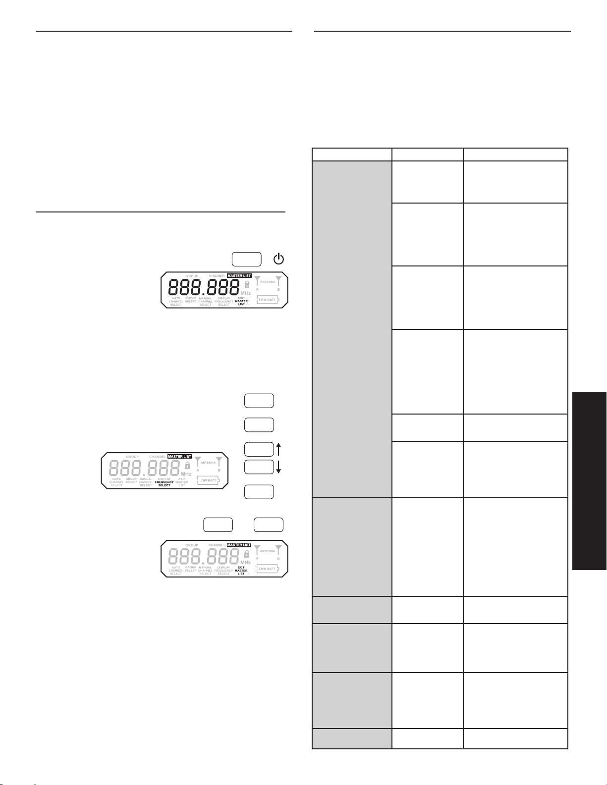
888.888
GROUP
CHANNEL
AUTO
CHANNEL
SELECT
GROUP
SELECT
MANUAL
CHANNEL
SELECT
DISPLAY
FREQUENCY
SELECT
ANTENNA
A
B
MASTER LIST
MHz
LOW BATT
888.888
GROUP
CHANNEL
AUTO
CHANNEL
SELECT
GROUP
SELECT
MANUAL
CHANNEL
SELECT
DISPLAY
FREQUENCY
SELECT
EXIT
MASTER
LIST
ANTENNA
A
B
MASTER LIST
MHz
LOW BATT
Selección de banda de frecuencias
La mayoría de los países regula estrictamente las frecuencias de radio utilizadas para la transmisión inalámbrica de información. Estas regulaciones definen los dispositivos que pueden
utilizar frecuencias determinadas y ayudan a limitar la cantidad de interferencias de RF (radiofrecuencias) en todas las comunicaciones inalámbricas.
Para contar con flexibilidad suficiente para trabajar en todo el mundo, los receptores SLX se ofrecen en diversos modelos, cada uno de ellos con una gama de frecuencias particular. Cada gama
de frecuencias, o banda, comprende hasta 24 MHz del espectro de difusión inalámbrica.
Para facilitar la preparación del sistema y protegerlo contra las interferencias de RF, cada sistema viene con grupos múltiples de frecuencias predefinidas y canales.
Cuando se utiliza un solo sistema SLX, en general no es necesario cambiar su frecuencia de
funcionamiento. En una instalación que tenga varios sistemas receptores/transmisores, cada
sistema deberá funcionar en un canal diferente. El sistema de grupos y canales proporciona una
separación óptima de frecuencias cuando se utilicen sistemas múltiples.
En una sola banda de frecuencias se pueden utilizar hasta 12 sistemas transmisores/receptores
diferentes en un solo lugar. En las regiones que disponen de bandas de frecuencias adicionales,
es posible tener hasta 20 sistemas en funcionamiento simultáneamente. Consulte con el distribuidor local de Shure para más información en cuanto a las bandas disponibles en su zona.
Lista maestra de frecuencias
Uso de la lista maestra
La “lista maestra” de frecuencias sólo debe
ser utilizada por usuarios expertos en situaciones que demandan la selección de una
frecuencia precisa. La “lista maestra” es un
índice completo de todas las frecuencias disponibles en intervalos de 25 kHz. (Intervalos
de 125 kHz en la banda JB.)
Para acceder a la lista maestra, mantenga
oprimido el botón menu mientras se enciende
el receptor SLX.
Selección de frecuencias en la lista
maestra
Cuando el mensaje FREQUENCY SELECT (selección de frecuencias)
destella, el botón select sirve para avanzar en sentido descendente por
las frecuencias disponibles; el botón menu sirve para avanzar en sentido ascendente. Oprima y suelte el botón para cambiar la frecuencia en
intervalos de 25 kHz; manténgalo oprimido para avanzar rápidamente.
Cuando se visualiza la frecuencia correcta, espere cinco segundos
para que la pantalla se desactive por inactividad, u oprima el botón
sync (sincronización).
Salida de la lista maestra
Para salir de la lista maestra y retornar al funcionamiento normal del sistema, oprima el botón
menu y después el botón select.
2x
menu
+
menu
select
select
menu
sync
menu select
Sugerencias para mejorar el
rendimiento del sistema
• Mantenga una trayectoria visual entre el transmisor y la antena
• No coloque el receptor cerca de superficies metálicas ni de equipos digitales
(reproductores de CD, computadoras, etc.).
• Fije el cable del adaptador de CA al receptor usando el gancho retenedor de
cable
• Si se instala el receptor en un rack, instale las antenas en la parte delantera
Problema Estado del indicador Solución
No hay sonido o es débil
Hay distorsión o ráfagas
de ruido no deseado
El nivel de distorsión aumenta gradualmente
El nivel de sonido es
diferente cuando se
conecta la guitarra o
micrófono con un cable,
o si se usan guitarras
diferentes
Se despliega el mensaje
de advertencia “FULL”
en el receptor
No es posible apagar el
transmisor
29
Luz de alimentación del
transmisor apagada
Pantalla LCD del receptor apagada
La pantalla del receptor
indica actividad de la
antena
La pantalla del receptor no indica actividad
alguna en las antenas;
las luces de alimentación del transmisor
y receptor están
iluminadas
La luz de alimentación
del transmisor se ilumina o destella roja
Se despliega el mensaje de advertencia
INCOMPATIBLE en el
transmisor
La pantalla del receptor
indica actividad de la
antena
La luz de alimentación
del transmisor se ilumina o destella roja
La luz del transmisor
destella roja
•Encienda el transmisor
•Verifiquequelosindicadores+/-
de las pilas correspondan con los
bornes del transmisor
•Inserte una pila nueva
•Asegúrese de que el adaptador
de CA esté bien conectado a un
tomacorriente y al conector DC
INPUT (entrada de CC) en el
panel trasero del receptor
•Asegúrese de que el tomacorriente de CA funcione y suministre
el voltaje adecuado
•Oprima el botón de silenciamiento
del transmisor
•Aumente el volumen del receptor
•Aumente la ganancia del
transmisor
•Revise el cable de conexión entre
el receptor y el amplificador o consola mezcladora
•Extienda las antenas del receptor
en sentido vertical
•Aleje el receptor de todo objeto
metálico
•Verifiquequehayaunatrayectoria
visual entre el transmisor y el
receptor
•Acerque el transmisor al receptor
•Verifiquequeelreceptoryel
transmisor estén usando la misma
frecuencia
Reemplace las pilas del transmisor
El mensaje de advertencia
INCOMPATIBLE indica que el
receptor y el transmisor están transmitiendo en bandas de frecuencias
diferentes. Comuníquese con el
distribuidor de equipos Shure para
recibir ayuda.
•Elimine las fuentes cercanas de
interferencias de RF (reproductores de CD, computadoras, efectos
digitales, sistemas de monitores
por auriculares, etc.)
•Cambie el receptor y el transmisor
a una frecuencia diferente
•Reduzca la ganancia del
transmisor
•Reemplace la pila del transmisor
•Si se utilizan sistemas múltiples,
aumente la separación entre las
frecuencias de los sistemas.
Reemplace las pilas del transmisor
Ajuste la ganancia del transmisor y
el volumen del receptor según sea
necesario
El mensaje de advertencia FULL
indica que todos los canales disponibles en el grupo seleccionado
actualmente se encuentran en uso.
Cuando esto suceda, reprograme
todos los sistemas para utilizar un
grupo diferente.
Reemplace las pilas del transmisor
Español
Page 30

Accesorios y piezas de repuesto
Accesorios opcionales
Estuche de transporte WA610
Rejilla negra para BETA 58A RK323G
Rejilla negra para BETA 87A y BETA 87C RK324G
Repuestos
Adaptador de pedestal para micrófono (SLX2) WA371
Bolsa con cremallera (SLX1) 26A13
Bolsa con cremallera (SLX2) 26A14
Barra para rack corta 53A8611
Barra para rack larga 53A8612
Barra de enlace 53B8443
Cables de extensión para antenas (2) (2) 95A9023
Defensas protectoras (receptor SLX4) (4) (4) 90A8977
AdaptadordeCA(120VCA,60Hz) PS21
AdaptadordeCA(220VCA,50Hz) PS21AR
AdaptadordeCA(230VCA,50/60Hz,enchufeeuropeo) PS21E
AdaptadordeCA(230VCA,50/60Hz) PS21UK
AdaptadordeCA(100VCA,50/60Hz) PS21J
Cápsula SM58® con rejilla (SLX2/SM58) RPW112
Cápsula SM86 con rejilla (SLX2/SM86) RPW114
Cápsula BETA 58A® con rejilla (SLX2/BETA 58) RPW118
Cápsula BETA 87A con rejilla (SLX2/BETA 87A) RPW120
Cápsula BETA 87C con rejilla (SLX2/BETA 87C TM) RPW122
Rejilla plateada mate para SM58® (SLX2/SM58) RK143G
Rejilla plateada mate para SM86 (SLX2/SM86) RPM226
Rejilla plateada mate para BETA 58A® (SLX2/BETA 58) RK265G
Rejilla plateada mate BETA 87A (SLX2/BETA 87A) RK312
Rejilla plateada mate BETA 87C (SLX2/BETA 87C TM) RK312
Gancho para cinturón 44A8030
Antena de 1/4 onda (470 - 752 MHz) UA400B
Antena de 1/4 onda (774 - 952 MHz) UA400
CERTIFICACIONES
SLX1, SLX2, SLX4
Este aparato digital de categoría B cumple la norma canadiense ICES-003.
Cet appareil numérique de la classe B est conforme à la norme NMB-003 du Canada.
Satisface los requisitos de las normas de compatibilidad electromagnética EN 300 422, Partes
1 y 2, y EN 301 489, Partes 1 y 9.
Satisface los requisitos esenciales de la Directriz 99/5/EC de RTTE en Europa. Califica para
portar el distintivo CE.
SLX1, SLX2
Certificado bajo la FCC, partes 74. (FCC ID: DD4SLX1, DD4SLX2). Certificado en Canadá
por la IC bajo las normas RSS-123 y RSS-102. (IC: 616A-SLX1, 616A-SLX1G5, 616A-SLX2,
616A-SLX2G5).
SLX4
Aprobado bajo la provisión de Declaración de homologación (DoC) de la parte 15 de las normas de la FCC. Certificado en Canadá por la IC según la norma RSS-123. (IC: 616A-SLX4,
616A-SLX4G5).
El uso de este dispositivo está sujeto a las dos condiciones siguientes: (1) no se permite que
este dispositivo cause interferencias y (2) este dispositivo deberá aceptar cualquier interferencia,
incluso la que pudiera causar su mal funcionamiento.
La Declaración de homologación para CE puede obtenerse de Shure, Incorporated o a través
de cualquiera de sus representantes europeos. Para la información de contacto, por favor visite
www.shure.com
La Declaración de homologación para CE puede obtenerse de: www.shure.com/europe/
compliance
Representante autorizado en Europa:
Shure Europe GmbH
Casa matriz para Europa, Medio Oriente y Africa
Departamento: Aprobación para región de EMEA
Jakob-Dieffenbacher-Str. 12,
75031 Eppingen, Germany
Teléfono: +49-7262-92 49 0
Fax: +49 7262-92 49 11 4
Correoelectrónico:info@shure.de
INFORMACION PARA OBTENCION DE LICENCIAS
Licencia de uso: Se puede requerir una licencia ministerial para utilizar este equipo en algunas
áreas. Consulte a la autoridad nacional sobre los posibles requisitos. Las modificaciones o los
cambios efectuados sin la aprobación expresa de Shure Incorporated podrían anular la autorización concedida para usar el equipo. La obtención de licencias para el uso de equipos de
micrófonos inalámbricos Shure es responsabilidad del usuario, y la otorgabilidad de licencias
dependerá de la clasificación y la aplicación del usuario y de la frecuencia seleccionada. Shure
recomienda enfáticamente al usuario ponerse en contacto con las autoridades de telecomunicaciones correspondientes respecto a la obtención de licencias antes de seleccionar y solicitar
frecuencias.
Antenna Combiners and Accessories
Antennas and receivers must be from the same band.
The supplied 1/4 wave antennas can be used when mounted directly to the UA844. If antennas
are remote mounted, 1/2 wave antennas must be used.
Antennas and cables are for use with UA844, and cannot be used with stand-alone SLX receivers
Passive Antenna/Splitter Combiner Kit
(recommended for 2 receivers)
25’ Antenna Cable UA825
50’ Antenna Cable UA850
100’Antenna Cable UA100
1/2 Wave Antenna Remote Mount Kit UA505
UHF Antenna Power Distribution Amplifier
(recommended for 3 or more receivers)
U.S.A. UA844US
Europe UA844E
UK UA844UK
H5 Band UA820H
J3 Band UA820F
L4 Band UA820L
P4, Q4 Bands UA820B
R13, R5, S6, JB Bands UA820A
UA221
1/2 wave antenna
INFORMACION PARA EL USUARIO
Este equipo ha sido probado y hallado en cumplimiento con los límites establecidos para
un equipo digital categoría B, según la parte 1 de las normas de la FCC. Estos límites están
diseñados para brindar una protección razonable contra interferencias perjudiciales en instalaciones residenciales. Este equipo genera, emplea y puede emitir energía de radiofrecuencia
y, si no se instala y utiliza de acuerdo con las instrucciones, es posible que cause interferencias perjudiciales a las comunicaciones por radio. Sin embargo, no se garantiza que no se
produzcan interferencias en una instalación concreta. Si se determina que el presente equipo
ocasiona interferencias dañinas a la recepción de señales de radio o televisión, lo que puede
verificarse al encender y apagar el equipo, se recomienda al usuario corregir la interferencia
tomando una o más de las siguientes medidas:
• Cambie la posición de la antena del receptor.
• Aumente la distancia entre el equipo y el receptor.
• Conecte el equipo a un tomacorriente de un circuito diferente al cual se ha conectado el
receptor.
• Consulte al concesionario.
Nota: Las pruebas de conformidad con las normas de EMC suponen el uso de cables de los
tipos provistos y recomendados. Si se usan cables de otro tipo se puede degradar el rendimiento de EMC.
Las modificaciones o los cambios efectuados sin la aprobación expresa del fabricante
podrían anular la autorización concedida al usuario para usar el equipo.
30
Page 31

SLX
mute select
Shure SLX Sem Fio
Sem fio inteligente e de funcionamento
contínuo
Parabéns! Benvindo ao Shure SLX Sem Fio. Seu novo sistema é resistente, confiável, de fácil instalação e
operação e produz uma pureza de áudio excelente. Seja você um vocalista, guitarrista ou instrumentista,
seu sistema SLX sem fio lhe mostrará quão fácil é o sistema sem fio e quão boa é a qualidade de som
deste sistema.
Benvindo ao mundo do SLX: Sem fio inteligente e de funcionamento contínuo
Componentes do Sistema
Todos os sistemas incluem:
Fonte de alimentação
-
+
Receptor SLX4
Duas Antenas de 1/4 Comprimento de Onda
Acessórios do Bastidor
2 Pilhas AA (4 em sistemas combinados)
O sistema de guitarra inclui:
O sistema do vocalista inclui:
Cápsula de Microfone (opção do
SM58®, SM86, Beta 58A®, Beta
87A™ ou Beta 87C™)
Cachimbo de microfone
Transmissor de mão SLX2
Cabo de guitarra de 1/4” para mini de 4
Os sistemas de microfone de lapela, microfone de cabeça e dos
instrumentos incluem:
WL93
-
pinos
+
Calços de borracha com 8 parafusos
Transmissor portátil SLX1
Português
WH30
WL184/
WL185
Microfone (opção de WL93, WL184 ou WL185, WH30 ou Beta 98H/C™).
Beta 98H/C™
Transmissor portátil SLX1
31
Page 32

ANTENNA B
POWER
MIC OUT LINE OUT VOLUME ANTENNA A
BALANCED
LOW Z
UNBALANCED
HIGH Z
12–18 V
170 mA
SHURE INCORPORATED
NILES, IL 60714
SLX4 RECEIVER
IC: 616A–SLX4
N108
• 1 x UA844
• 1 x UA844
ANTENNA B
POWER
MIC OUT LINE OUT VOLUME ANTENNA A
BALANCED
LOW Z
UNBALANCED
HIGH Z
12–18 V
170 mA
SHURE INCORPORATED
NILES, IL 60714
SLX4 RECEIVER
IC: 616A–SLX4
N108
ANTENNA B
POWER
MIC OUT LINE OUT VOLUME ANTENNA A
BALANCED
LOW Z
UNBALANCED
HIGH Z
12–18 V
170 mA
SHURE INCORPORATED
NILES, IL 60714
SLX4 RECEIVER
IC: 616A–SLX4
N108
ANTENNA B
POWER
MIC OUT LINE OUT VOLUME ANTENNA A
BALANCED
LOW Z
UNBALANCED
HIGH Z
12–18 V
170 mA
SHURE INCORPORATED
NILES, IL 60714
SLX4 RECEIVER
IC: 616A–SLX4
N108
• 1 x UA221
ANTENNA B
POWER
MIC OUT LINE OUT VOLUME ANTENNA A
BALANCED
LOW Z
UNBALANCED
HIGH Z
12–18 V
170 mA
SHURE INCORPORATED
NILES, IL 60714
SLX4 RECEIVER
IC: 616A–SLX4
N108
ANTENNA B
POWER
MIC OUT LINE OUT VOLUME ANTENNA A
BALANCED
LOW Z
UNBALANCED
HIGH Z
12–18 V
170 mA
SHURE INCORPORATED
NILES, IL 60714
SLX4 RECEIVER
IC: 616A–SLX4
N108
• 1 x UA221
SLX4 Receiver
Receptores SLX montados em Bastidor
Um Receptor
• Todos os acessórios fornecidos
Acrescentando calços de borracha protetores
Recomendado se o receptor não estiver montado em bastidor. Use os parafusos
fornecidos.
Dois Receptores
• Acessórios Necessários: 1 x UA440
UA440
SLX4
12–18 V
170 mA
BALANCED
LOW Z
POWER
ANTENNA B
SHURE INCORPORATED
NILES, IL 60714
UNBALANCED
SLX4 RECEIVER
HIGH Z
IC: 616A–SLX4
MIC OUT LINE OUT VOLUME ANTENNA A
Dois Receptores com Divisor de Antena UA221/Kit
Combinador
• Acessórios Necessários: 1 x UA221
SLX4 SLX4
12–18 V
170 mA
BALANCED
LOW Z
POWER
ANTENNA B
SHURE INCORPORATED
NILES, IL 60714
UNBALANCED
SLX4 RECEIVER
HIGH Z
IC: 616A–SLX4
MIC OUT LINE OUT VOLUME ANTENNA A
12–18 V
170 mA
BALANCED
N108
LOW Z
POWER
ANTENNA B
SHURE INCORPORATED
NILES, IL 60714
UNBALANCED
SLX4 RECEIVER
HIGH Z
IC: 616A–SLX4
MIC OUT LINE OUT VOLUME ANTENNA A
UA221
N108
Três ou Quatro Receptores
• Acessórios Necessários: 1 x UA844
UA844
UHF ANTENNA / POWER DISTRIBUTION SYSTEM
SLX4 SLX4
SLX4
N108
32
12–18 V
170 mA
BALANCED
LOW Z
POWER
ANTENNA B
12–18 V
170 mA
BALANCED
LOW Z
POWER
ANTENNA B
SHURE INCORPORATED
NILES, IL 60714
UNBALANCED
SLX4 RECEIVER
HIGH Z
N108
IC: 616A–SLX4
MIC OUT LINE OUT VOLUME ANTENNA A
SHURE INCORPORATED
NILES, IL 60714
UNBALANCED
SLX4 RECEIVER
HIGH Z
N108
IC: 616A–SLX4
MIC OUT LINE OUT VOLUME ANTENNA A
12–18 V
170 mA
POWER
ANTENNA B
UA844
POWER
UNBALANCED
BALANCED
HIGH Z
LOW Z
MIC OUT LINE OUT VOLUME ANTENNA A
SHURE INCORPORATED
NILES, IL 60714
SLX4 RECEIVER
IC: 616A–SLX4
N108
Page 33

ANTENNA A
SHURE INCORPORATED
NILES, IL 60714
SLX4 RECEIVER
Instalação de um Único Sistema
Siga estes passos ao usar um sistema SLX único:
Seleção Automática de Frequência
Procura um canal disponível e configura o receptor para aquele canal.
Configuração Automática do Transmissor
1. Ligue o transmissor.
2. Abra o compartimento da pilha do transmissor para exibir a porta de infravermelho (IR)
3. Com a porta IR exposta ao receptor, aperte sinc..
4. Mantenha o botão sinc pressionado até a luz vermelha parar de piscar no receptor e no transmissor.
5. Quando a luz de pronto do receptor acender, o sistema está pronto para uso.
6. Feche o compartimento da pilha do transmissor.
Instalação de um Sistema Múltiplo
Siga estes passos ao usar os sistemas múltiplos SLX em uma instalação única:
1. Ligue todos os receptores e desligue todos os transmissores.
2. Configure todos os receptores com o mesmo grupo de frequência.
3. Realize a Seleção Automática de Frequência a partir da seção de Configuração de Sistema Único acima.
4. Ligue o primeiro transmissor.
5. Realize a Configuração Automática do Transmissor a partir da seção de Configuração de Sistema Único acima.
6. Repita para cada sistema.
Assegure-se de que somente uma porta IR do transmissor esteja exposta ao sincronizar um sistema.
Interruptor Liga/Desliga
Bata de leve para ligar, segure para
desligar.
12–18 V
160 mA
BALANCED
LOW Z
POWER
ANTENNA B
SHURE INCORPORATED
NILES, IL 60714
UNBALANCED
SLX4 RECEIVER
HIGH Z
N108
IC: 616A–SLX4
MIC OUT INSTRUMENT OUTVOLUME ANTENNA A
Controle de Volume do Receptor
O dial de controle de volume normalmente está à esquerda na posição horária. Girando o
dial no sentido anti-horário diminui o nível de saída do receptor.
Se forem necessários ajustes, use uma pequena chave de fenda para girar o dial.
ANTENNA B
12–18 V
160 mA
POWER
MIC OUT INSTRUMENT OUT VOLUME ANTENNA A
SHURE INCORPORATED
NILES, IL 60714
SLX4 RECEIVER
Português
VOLUME
33
Page 34

888.888
GROUP
CHANNEL
AUTO
CHANNEL
SELECT
GROUP
SELECT
MANUAL
CHANNEL
SELECT
DISPLAY
FREQUENCY
SELECT
EXIT
MASTER
LIST
MASTER LIST
MHz
LOW BATT
888.888
GROUP
CHANNEL
AUTO
CHANNEL
SELECT
GROUP
SELECT
MANUAL
CHANNEL
SELECT
DISPLAY
FREQUENCY
SELECT
EXIT
MASTER
LIST
ANTENNA
A
B
MASTER LIST
MHz
888.888
GROUP
CHANNEL
AUTO
CHANNEL
SELECT
MANUAL
CHANNEL
SELECT
DISPLAY
FREQUENCY
SELECT
EXIT
MASTER
LIST
ANTENNA
A
B
MASTER LIST
MHz
LOW BATT
888.888
GROUP
CHANNEL
AUTO
CHANNEL
SELECT
GROUP
SELECT
MANUAL
CHANNEL
SELECT
DISPLAY
FREQUENCY
SELECT
EXIT
MASTER
LIST
ANTENNA
A
B
MASTER LIST
MHz
LOW BATT
888.888
GROUP
CHANNEL
AUTO
CHANNEL
SELECT
GROUP
SELECT
MANUAL
CHANNEL
SELECT
EXIT
MASTER
LIST
ANTENNA
A
B
MASTER LIST
MHz
LOW BATT
888.888
GROUP
CHANNEL
AUTO
CHANNEL
SELECT
GROUP
SELECT
MANUAL
CHANNEL
SELECT
DISPLAY
FREQUENCY
SELECT
EXIT
MASTER
LIST
ANTENNA
A
B
MASTER LIST
MHz
LOW BATT
SLX4 LCD
Advertência de Grupo Cheio
A advertência de CHEIO indica que todos os canais disponíveis no grupo atualmente selecionado estão em uso. Quando isto ocorre, reprograme todos os sistemas para um grupo
alternativo.
Aperte o botão de menu ou selecionar para sair da tela de advertência.
Condição da Pilha do Transmissor
Indica uma condição de carga fraca da pilha do transmissor.
Condição da Antena
Indica a atividade de RF. Somente uma antena está ativada de cada
vez.
Programação do Receptor SLX4
Qualquer opção exibida na tela terá normalmente seu “tempo esgotado” (“time out”) após cinco segundos.
Seleção do Grupo
Permite a seleção manual de um grupo de frequência. Ao apertar selecionar o
número do grupo é aumentado em uma unidade. Quando for exibida a frequência
correta, aguarde cinco segundos para que a tela tenha seu tempo esgotado ou aperte
sinc. Para obter melhores resultados ao operar sistemas múltiplos, configure todos
os sistemas com um único grupo e em seguida configure cada sistema com um único
canal dentro deste grupo.
Exibição de Frequência
Exibe a frequência atual em MHz durante aproximadamente 5 segundos. Aperte e
mantenha apertado para aumentar a duração da exibição.
Bloqueie ou Desbloqueie as Configurações do Receptor
Mantenha apertada a chave selecionar e aperte menu para bloquear ou desbloquear o receptor. Quando bloqueada, as configurações atuais do receptor não
podem ser alteradas.
Seleção Manual de Canal
Permite a seleção manual de um canal de frequência. Ao apertar selecionar o
número do canal é aumentado em uma unidade. Quando for exibida a frequência correta, aguarde cinco segundos para que a tela tenha seu tempo esgotado
ou aperte sinc.
GROUP
SELECT
MANUAL
CHANNEL
SELECT
DISPLAY
FREQUENCY
34
Page 35

SLX1 & SLX2 Transmitters
SLX2
SLX
SLX1
Troca de Pilhas
• A vida útil esperada para uma pilha alcalina é de aproximadamente 8 horas.
• Quando a luz do transmissor acender vermelha, as pilhas devem ser trocadas
imediatamente, como mostrado à esquerda.
mute select
Interruptor Liga-desliga / mudo
Aperte e mantenha apertado para ligar ou desligar. Aperte e solte para mudo ou desativar mudo.
Para evitar ativação acidental do mudo durante uma apresentação, bloqueie o painel dianteiro
enquanto o microfone estiver em uso.
Indicador de Energia / Infravermelho (IR) / Mudo
Verde: pronto
Âmbar: mudo ligado
Vermelho piscando: Transmissão IR em andamento
Vermelho aceso: pilha fraca
Vermelho pulsando: bateria descarregada (o transmissor não pode ser ligado até que as
baterias sejam trocadas)
SLX
mute select
Como Usar o Transmissor Portátil
Prenda com presilha o transmissor a um cinto ou passe uma cinta de guitarra pela presilha do
transmissor conforme mostrado.
Para obter melhores resultados, passe o transmissor até que o cinto seja pressionado contra a
base da presilha.
Português
35
Page 36

i8 i8
Incompatible
CHANNEL
i8 i8
MASTER LIST
Incompatible
GROUP
i8 i8
Incompatible
GROUP
CHANNEL
i8 i8
GROUP
CHANNEL
i8 i8
GROUP
CHANNEL
i8 i8
Incompatible
GROUP
CHANNEL
Se o LED do receptor indicar que o volume de
entrada está sobrecarregando o receptor, tente
mudar o ganho para um ajuste mais baixo.
SLX2
Ajuste do Ganho
Acesse o interruptor de ajuste de ganho desparafusando o
cabeçote do microfone.
Há dois ajustes de ganho disponíveis no SLX2. Selecione um
ajuste apropriado para o volume vocal e para o ambiente da
apresentação. Use a ponta de uma caneta ou uma chave de
fenda pequena para mover o interruptor.
• 0dB: Para apresentação vocal baixa até normal.
• –10dB: Para desempenho vocal alto.
SLX1
Ajuste do Ganho
Estão disponíveis três ajustes de ganho no SLX1.
Selecione o ajuste adequado para seu instrumento.
• mic: Microfone (amplificação mais alta)
• 0: Guitarra com captações passivas (amplificação
média)
• –10: Guitarra com captações ativas (amplificação
mais baixa)
Programação do Transmissor SLX1 e SLX2
Selecione Manualmente um Grupo e/ou Canal
1. Aperte e mantenha apertado o botão selecionar até que as exibições de GRUPO e CANAL comecem a
se alternar.
2. Para alterar a configuração de grupo, solte o botão selecionar enquanto GRUPO estiver sendo exibido.
Quando GRUPO estiver piscando, ao apertar selecionar a configuração de grupo é aumentada em uma
unidade.
3. Para alterar a configuração de canal, solte o botão selecionar enquanto CANAL estiver sendo exibido.
Quando CANAL estiver piscando, ao apertar selecionar a configuração de canal é aumentada em uma
unidade.
select
5
-10 0 mic
select
BIAS
AUDIO
0dB
SLX
mute select
-10dB
Bloqueie ou Desbloqueie as Configurações
do Transmissor
Aperte os botões mudo e selecionar simultaneamente para bloquear ou desbloquear as configurações do transmissor. Quando
bloqueadas, as configurações atuais não podem ser alteradas
manualmente. O bloqueio do transmissor não desativa o
sincronismo de infravermelho.
select
+
SLX1 & SLX2 LCD
Condição da Pilha
Indica a carga remanescente nas pilhas do transmissor.
Advertência de Frequência INCOMPATÍVEL
AadvertênciadeINCOMPATÍVELindicaqueoreceptoreotransmissor
estão configurados para bandas de frequência incompatíveis. Entre em
contato com seu revendedor Shure para obter assistência.
Indicador da Lista Mestre
Indica que uma lista mestra de frequência está atualmente em uso. Não é
exibida nenhuma informação de grupo ou canal.
Observação: o transmissor não pode ser usado para alterar as configurações da lista mestre.
36
Page 37

SLX
Faixa de trabalho
LinhadeVista
Resposta da Frequência de Áudio
Distorção Harmônica Total
Ref. ±38 kHz de desvio com 1kHz de tom
Escala Dinâmica
Faixa de Temperatura de Operação
Polaridade de Áudio do Transmissor
100 m (300 pés)
Observação: A faixa real de alcance depende da
absorção, reflexão e interferência do sinal de RF.
45–15000 Hz
Observação: Depende do tipo de microfone
<0.5%, típico
>100 dB, Ponderação A
-18°C (0°F) a +50°C (122°F)
Observação: As características da bateria podem
limitar esta faixa.
Pressão positiva no diafragma do microfone (ou
tensão positiva aplicada na ponta do plugue de
fone WA302) produz uma tensão positiva no
pino 2 (em relação ao pino 3 da saída de baixa
impedância) e na ponta da saída de 1/4 de polegada de alta impedância.
SLX1
Nível de Entrada de Áudio posição de ganho
mic:
−10dBVmáximo
0dB:
+10dBVmáximo
–10dB:
+20dBVmáximo
Faixa de ajuste de ganho
Impedância de Entrada
Potência de Saída de RF
Distribuição dos Pinos
TA4M
Dimensões
Peso
Alojamento
Requisitos de Alimentação Elétrica
Vida Útil da Bateria
30 dB
1MΩ
10–30 mW
varia conforme a região
1:
terra (blindagem do cabo)
2:
Polarizaçãode+5V
3:
áudio
4:
Ligado por meio de carga
ativa ao terra (Cabo adaptador no instrumento, pino
4 flutua)
108mm x 64mm x 19mm (A x L x P)
81 g (3 oz.), sem baterias
Aço galvanizado
2 pilhas alcalinas “AA” ou pilhas recarregáveis
até 8 horas (alcalina)
SLX2
Nível Máximo de Entrada em ganho míni-
Faixa de ajuste de ganho
Potência de Saída de RF
Dimensões
Peso
Alojamento
Requisitos de Alimentação Elétrica
Vida Útil da Bateria
mo de –10 dB:
em ganho míni-
mo de 0 dB:
10 dB
10–30 mW
varia conforme a região
254mm X 51mm diâmetro (10 X 2pol.)
290 g (10.2oz.) (sem baterias)
Alça PC/ABS Moldada e cuba da pilha
2 pilhas alcalinas “AA” ou pilhas recarregáveis
até 8 horas (alcalina)
+2dBV
–8dBV
SLX4
Dimensões
Peso
Alojamento
Sensibilidade
Requisitos de Alimentação Elétrica
Configuração
Nível Máximo de Saída
Ref. ±38 kHz de desvio com 1kHz de tom
Impedância Conector XLR:
Distribuição dos Pinos Conector XLR:
Rejeição de imagem
Escala de Ajuste do Volume
42mm X 197mm X 134mm (A x L x P)
816 g (1 lb 13oz.)
Aço galvanizado
-105 dBm para 12 dB SINAD, típico
12–18VDC@150mA,alimentadopelafontede
alimentação externa (ponta positiva)
Impedância balanceada
Conector XLR:
Conector de 6,35
mm (1/4 pol.):
Conector de 6,35
mm (1/4 pol.):
Conector de 6,35
mm (1/4 pol.):
>70 dB, típico
0 dB a -25 dB
–13dBV(emcargade
600Ω)
–2dBV(emcargade
3kΩ)
200Ω
1kΩ
1=terra, 2=áudio, 3=sem
áudio
Ponta=áudio, Anel=sem
áudio, Adaptador=terra
Faixa de Freqüência e Potência de
Saída do Transmissor
Banda Faixa Potência do transmissor
G4 470 a 494 MHz 30 mW
G4E 470 a 494 MHz 30 mW
G5 494 a 518 MHz 30 mW
G5E 494 a 518 MHz 30 mW
G8 494.200 a 509.825 MHz 30 mW
H5 518 a 542 MHz 30 mW
J3 572 a 596 MHz 30 mW
L4 638 a 662 MHz 30 mW
L4E 638 a 662 MHz 30 mW
P4 702 a 726 MHz 30 mW
R13 794 a 806 MHz 20 mW
R5 800 a 820 MHz 20 mW
X4 925 a 932 MHz 10 mW
S6 838 a 865 MHz 10 mW
S10 823 a 832 MHz 10 mW
JB 806 a 810 MHz 10 mW
R19 794 a 806 MHz 10 mW
Q4 740 a 752 MHz 10 mW
K3E 606 a 630 MHz 10 mW
OBSERVAÇÃO:
Este equipamento de rádio foi projetado para uso em aplicações profissionais de entretenimento musical e em aplicações similares.
Este equipamento de Rádio pode ter a capacidade de operar em algumas freqüências não
autorizadas na sua região. Entre em contato com o órgão nacional responsável para obter
informações sobre as freqüências autorizadas e níveis de potência de RF para microfones
sem fio.
Português
37
Page 38

888.888
GROUP
CHANNEL
AUTO
CHANNEL
SELECT
GROUP
SELECT
MANUAL
CHANNEL
SELECT
DISPLAY
FREQUENCY
SELECT
ANTENNA
A
B
MASTER LIST
MHz
LOW BATT
888.888
GROUP
CHANNEL
AUTO
CHANNEL
SELECT
GROUP
SELECT
MANUAL
CHANNEL
SELECT
DISPLAY
FREQUENCY
SELECT
EXIT
MASTER
LIST
ANTENNA
A
B
MASTER LIST
MHz
LOW BATT
Seleção da Banda de Frequência
A maioria dos países regulam de perto as radiofrequências na transmissão de informações sem
fio. Estes regulamentos informam quais dispositivos podem usar que frequências e ajudam a
limitar a quantidade de interferência de RF (radiofrequência) em todas as comunicações sem fio.
Para ser suficientemente flexível para operar em todo o mundo, os receptores SLX estão disponíveis em diversos modelos, cada um com uma faixa exclusiva de frequência. Cada faixa ou
banda de frequência abrange até 24 MHz do espectro de radiodifusão sem fio.
Para facilitar o ajuste do sistema e proteger contra a interferência de RF, cada sistema vem com
diversos grupos e canais de frequência predefinidos.
Ao utilizar um único sistema SLX, a frequência de operação normalmente não precisará ser
trocada. Em uma instalação com múltiplos sistemas de receptor/transmissor, cada sistema deve
operar em um canal separado. O sistema de grupo e canal proporciona uma ótima dispersão de
frequência ao se utilizarem sistemas múltiplos.
Dentro de uma única banda de frequência, podem ser utilizados até 12 sistemas de transmissor/
receptor em uma única instalação. Em regiões onde estejam disponíveis bandas de frequência
adicionais,épossíveloperaraté20sistemassimultaneamente.Verifiquejuntoaorevendedor
Shure local para obter mais informações sobre as bandas que se encontram disponíveis na sua
área.
Lista de Frequências Mestre
Uso da Lista Mestre
A “Lista Mestre” de frequências deve ser
acessada somente por usuários experientes em situações que requeiram seleção
precisa de frequência. A “Lista Mestre” é
um índice completo de todas as frequências
disponíveis, em incrementos de 25 kHz. (incrementos de 125 kHz na banda JB).
Para acessar a Lista Mestre, mantenha
apertado o botão menu enquanto ligar o
receptor SLX.
Selecione Frequências na Lista Mestre
Quando SELECIONAR FREQUÊNCIA estiver piscando, o botão selecionar percorre para baixo todas as frequências; o botão menu percorre para cima. Aperte e solte para mudar a frequência em incrementos de 25 kHz; aperte e mantenha apertado para rolar rapidamente.
Quando for exibida a frequência correta, aguarde cinco segundos para
que a tela tenha seu tempo esgotado ou aperte sinc.
Saia da Lista Mestre
Para sair da Lista Mestre e retornar para as operações normais do sistema, aperte menu, e em
seguida selecionar.
2x
menu
+
menu
select
select
menu
sync
menu select
Dicas para Melhorar o Desempenho
do Sistema
• Mantenha uma linha de visada entre o transmissor e a antena.
• Evite colocar o receptor próximo de superfícies metálicas ou de quaisquer
equipamentos digitais (CD players, computadores, etc.)
• Prenda o cabo do adaptador AC ao receptor usando um anel retentor de cabo
• Caso o receptor esteja sendo montado em bastidor, monte frontalmente as
antenas
Problema Condição do
Sem som ou som
fraco
Distorção ou
aumentos repentinos de ruído
indesejáveis
O nível de distorção apresenta um
aumento gradativo.
Nível de som
diferente de uma
guitarra elétrica
ou microfone ou
quando estiver
utilizando guitarras
diferentes
A advertência
FULL aparece no
receptor
Não pode desligar
o transmissor
Indicador
Luz de alimentação
do transmissor
desligada
LCD do receptor
desligado
O mostrador do
receptor indica a atividade da antena
O mostrador do
receptor indica que
não há nenhuma luz
acesa relativa à atividade de antena; de
alimentação do transmissor e receptor
A luz de alimentação
vermelha do transmissor está acesa ou
piscando vermelha
Advertência de
INCOMPATÍVELno
transmissor
O mostrador do
receptor indica a atividade da antena
A luz de alimentação
vermelha do transmissor está acesa ou
piscando vermelha
Luz do transmissor
piscando vermelha
Solução
Ligue o transmissor
Assegure-se de que os indicadores +/- na pilha
coincidem com os terminais do transmissor
Coloque uma bateria nova
Certifique-se de que o adaptador AC esteja
firmemente ligado à tomada elétrica e ao conector de entrada DC no painel traseiro do
receptor.
Certifique-se de que a tomada elétrica AC
esteja funcionando e de que forneça a tensão
adequada.
Aperte mudo no transmissor
Aumente o controle de volume do receptor
Aumente a configuração do interruptor de
ganho do transmissor
Verifiqueocabodeconexãoentreoreceptore
o amplificador ou mixer.
Estenda as antenas do receptor verticalmente
Afaste o receptor para longe de quaisquer objetos metálicos
Verifiqueseháumalinhadevisadaentreo
transmissor e o receptor
Coloque o transmissor mais próximo do
receptor
Verifiqueseoreceptoreotransmissorestão
utilizando a mesma freqüência
Substitua as pilhas do transmissor.
AadvertênciadeINCOMPATÍVELindicaque
o receptor e o transmissor estão configurados
para bandas de freqüência incompatíveis. Entre
em contato com seu revendedor Shure para
obter assistência.
Remova as fontes de interferência RF das proximidades (CD players, computadores, efeitos
digitais, monitores de ouvido, etc.)
Altere o receptor e o transmissor para uma
freqüência diferente
Reduza o ganho do transmissor
Substitua a pilha do transmissor.
Caso utilize sistemas múltiplos, aumente a dispersão de freqüência entre os sistemas.
Substitua as pilhas do transmissor.
Ajuste o ganho do transmissor e o volume do
receptor, conforme necessário
A advertência de FULL indica que todos os
canais disponíveis no grupo atualmente selecionado estão em uso. Quando isto ocorre,
reprograme todos os sistemas para um grupo
alternativo.
Substitua as pilhas do transmissor.
38
Page 39

Acessórios e Peças
Acessórios Opcionais
Grade Preta para BETA 58A RK323G
Grade Preta para BETA 87A e BETA 87C RK324G
Peças de reposição
Maleta de Transporte WA610
CERTIFICAÇÃO
SLX1, SLX2, SLX4
Este dispositivo digital Classe B está de acordo com a norma canadense ICES-003.
Cet appareil numérique de la classe B est conforme à la norme NMB-003 du Canada.
Atende aos requisitos de compatibilidade eletromagnética (EMC) de acordo com as Partes 1 e 2
da Norma EN 300 422 e as Partes 1 e 9 da Norma EN 301 489 .
Atende aos requisitos essenciais da Diretiva 99/5/CE R&TTE Europeia, aprovado para exibir a
marca CE.
Adaptador para Pedestal de Microfone (SLX2) WA371
Bolsa com Zíper (SLX1) 26A13
Bolsa com Zíper (SLX2) 26A14
Barra Curta para Bastidor 53A8611
Barra Longa para Bastidor 53A8612
Barra de Ligação 53B8443
Cabos de extensão da antena (2) (2) 95A9023
Calços amortecedores de borracha (Receptor SLX4) (4) (4) 90A8977
AdaptadordeAC(120VAC,60Hz) PS21
AdaptadordeAC(220VAC,50Hz) PS21AR
AdaptadordeAC(230VAC,50/60Hz,PlugueEuropeu) PS21E
AdaptadordeAC(230VAC,50/60Hz) PS21UK
AdaptadordeAC(100VAC,50/60Hz) PS21J
Cápsula SM58® com Tela (SLX2/SM58) RPW112
Cápsula SM86 com Tela (SLX2/SM86) RPW114
Cápsula BETA 58A® com Tela (SLX2/BETA 58) RPW118
Cápsula BETA 87A com Tela (SLX2/BETA 87A) RPW120
Cápsula BETA 87C com Tela (SLX2/BETA 87C TM) RPW122
Grade Prata Fosco para SM58® (SLX2/SM58) RK143G
Grade Prata Fosco para SM86 (SLX2/SM86) RPM226
Grade Prata Fosco para BETA 58A® (SLX2/BETA 58) RK265G
Grade prata Fosco para BETA 87A (SLX2/BETA 87A) RK312
Grade Prata Fosco para BETA 87C (SLX2/BETA 87C TM) RK312
Presilha para Cinto 44A8030
Antena de 1/4 de Onda (470 a 752 MHz) UA400B
Antena de 1/4 de Onda (774 a 952 MHz) UA400
SLX1, SLX2
Certificado de acordo com a Parte 74 da FCC. (FCC ID: DD4SLX1, DD4SLX2). Certificado
pelo IC no Canadá sob a RSS-123 e RSS-102. (IC: 616A-SLX1, 616A-SLX1G5, 616A-SLX2,
616A-SLX2G5).
SLX4
Aprovado sob a cláusula de Declaração de Conformidade da Parte 15 da norma da FCC.
Certificado pelo IC no Canadá sob a RSS-123. (IC: 616A-SLX4, 616A-SLX4G5).
A operação deste dispositivo está sujeita às seguintes condições: (1) este dispositivo não pode
causar interferência; e (2) este dispositivo deve aceitar quaisquer interferências, incluindo algumas que possam causar operação não desejada do dispositivo.
A Declaração de Conformidade da CE pode ser obtida da Shure Incorporated ou de qualquer um
dos seus representantes europeus. Para informações de contato, visite www.shure.com
A Declaração de Conformidade da CE pode ser obtida em: www.shure.com/europe/compliance
Representante Autorizado europeu:
Shure Europe GmbH
Headquarters Europe, Middle East & Africa
Department: EMEA Approval
Jakob-Dieffenbacher-Str. 12
75031 Eppingen, Germany
Telefone: +49 7262-92 49 0
Fax: +7262-92 49 11 4
E-mail:info@shure.de
INFORMAÇÕES SOBRE A LICENÇA
Licença: Em determinados locais, pode ser necessário obter uma autorização ministerial para operar este equipamento. Consulte a sua autoridade nacional sobre possíveis requisitos. Alterações
ou modificações não expressamente aprovadas pela Shure Incorporated podem anular a autorização do usuário para a operação do equipamento. A licença do equipamento de microfone sem
fio da Shure é de responsabilidade do usuário e a licença depende da classificação e aplicação
do usuário e da frequência selecionada. A Shure recomenda enfaticamente ao usuário contatar a
devida autoridade de telecomunicações com relação à devida licença antes de escolher e encomendar as frequências.
Accessori e combinatori per antenne
Le antenne e i ricevitori devono funzionare nella stessa banda.
Le antenne a 1/4 d’onda in dotazione sono utilizzabili montate direttamente
sull’UA844. Se le antenne devono essere montate a distanza, occorre adoperare
antenne a mezz’onda. Le antenne e i cavi vanno adoperati con l’UA844 e non sono
utilizzabili con ricevitori SLX singoli.
Kit splitter/combinatore per antenne passivo
Kit per montaggio remoto dell’antenna a mezz’onda UA505
(raccomandato per 2 ricevitori)
Cavo per antenna da 7,62 m (25 piedi) UA825
Cavo per antenna da 15,24 m (50 piedi) UA850
Cavo per antenna da 30,48 m (100 piedi) UA100
Distributore attivo di segnale per antenne UHF
(raccomandato per 3 o più ricevitori)
USA UA844US
Europa UA844E
UK UA844UK
Banda H5 UA820H
Banda J3 UA820F
Bande L4 UA820L
Bande P4, Q4 UA820B
Bande R13, R5, S6, JB UA820A
Antenne a mezz’onda
UA221
INFORMAÇÕES PARA O USUÁRIO
Este equipamento foi testado e está de acordo com os limites para um dispositivo digital Classe
B, segundo a Parte 15 das Normas do FCC. Estes limites foram projetados para fornecer razoável proteção contra interferência prejudicial em uma instalação residencial. Este equipamento
gera, usa e pode irradiar energia de radiofrequência e, se não for instalado e usado conforme as
instruções, pode causar interferência prejudicial às comunicações de rádio. Entretanto, não há
garantias de que não ocorrerão interferências em uma determinada instalação. Se este equipamento causar interferência prejudicial à recepção de rádio ou televisão, o que pode ser determinado ao desligar e ligar o equipamento, o usuário deve tentar corrigir a interferência tomando uma
das seguintes medidas:
• Reposicione a antena receptora.
• Aumente a distância entre o equipamento e o receptor.
• Conecte o equipamento em uma tomada de um circuito diferente do circuito da tomada onde o
receptor está conectado.
• Consulte o revendedor.
Observação:O teste de compatibilidade eletromagnética é baseado no uso dos tipos de cabos
recomendados e fornecidos com o equipamento. O uso de outros tipos de cabos pode degradar
o desempenho da compatibilidade eletromagnética.
Alterações ou modificações não expressamente aprovadas pelo fabricante podem anular a
autorização do usuário para a operação do equipamento.
39
Português
Page 40

EUROPEAN COUNTRY–GROUP MATRIX FREQUENCY BANDS
SLX H5 518-542 MHz, max. 30 mW
Country Code Frequency Range
Code de Pays Gamme de frequences
Länder-Kürzel Frequenzbereich
A, B, CH, CZ, D, E, EST 518–542 MHz *
F, GB, GR, H, I, IRL, L 518–542 MHz *
LT, M, NL, P, PL, SLO 518–542 MHz *
DK, FIN, N, S *
CY,LV,SK *
All other Countries *
SLX J3 572–596 MHz, max. 30 mW
Country Code Frequency Range
Code de Pays Gamme de frequences
Länder-Kürzel Frequenzbereich
A, B, CH, CZ, D, E, EST 572–596 MHz *
F, GB, GR, H, I, IRL, L 572–596 MHz *
LT, M, NL, P, PL, SLO 572–596 MHz *
DK, FIN, N, S *
CY,LV,SK *
All other countries *
P4 702–726 MHz, max. 30 mW
Country Code Frequency Range
Code de Pays Gamme de frequences
Länder-Kürzel Frequenzbereich
A, B, CH, CZ, D, E, EST 702–726 MHz *
F, GB, GR, H, I, IRL, L 702–726 MHz *
LT, M, NL, P, PL, SLO 702–726 MHz *
DK, FIN, N, S *
CY,LV,SK *
All other countries *
R5 800–820 MHz, max. 20 mW
Country Code Frequency Range
Code de Pays Gamme de frequences
Länder-Kürzel Frequenzbereich
B, CH, D, EST 800–820 MHz *
F, GB, GR, H, I, IRL, L 800–820 MHz *
FIN, LT, N, NL, P, PL, SLO 800–820 MHz *
CZ 815–820 MHz *
A,CY,DK,E,LV,M,S,SK *
All other countries *
SLX-L4/-L4E 638–662 MHz, max. 30 mW
Country Code Frequency Range
Code de Pays Gamme de frequences
Codice di paese: Gamme di frequenza
Código de país: Gama de frequencias
Länder-Kürzel Frequenzbereich
A, BG, CH, CY, CZ, D, EST 638–662 MHz *
F, GB, GR, H, I, IS, LT 638–662 MHz *
P, PL, S, SK, SLO 638–662 MHz *
B, DK, E, FIN, HR, IRL, L *
LV,M,N,NL,RO,TR *
All other countries *
SLX-G4E 470 - 494 MHz, max. 30 mW
Country Code Frequency Range
Code de Pays Gamme de frequences
Codice di paese Gamme di frequenza
Código de país Gama de frequencias
Länder-Kürzel Frequenzbereich
A, B, BG, CH, CY, CZ, D, EST 470 - 494 MHz *
F, GB, GR, H, I, IS, L, LT 470 - 494 MHz *
NL, P, PL, S, SK, SLO 470 - 494 MHz *
DK, FIN, M, N *
HR,E,IRL,LV,RO,TR *
all other countries *
S6 838–865 MHz, max. 10 mW
Country Code Frequency Range
Code de Pays Gamme de frequences
Länder-Kürzel Frequenzbereich
B, CH, D, EST
GB, H, I, IRL, L
LT, M, NL, P, PL, SLO
A, CY, CZ, DK, E, F, FIN
GR,N,LV,S,SK
838–865 MHz *
838–865 MHz *
838–865 MHz *
*
*
All other countries *
SLX-G5E 494 - 518 MHz, max. 30 mW
Country Code Frequency Range
Code de Pays Gamme de frequences
Codice di paese Gamme di frequenza
Código de país Gama de frequencias
Länder-Kürzel Frequenzbereich
A, B, BG, CH, CY, CZ, D, EST 494 - 518 MHz *
F, GB, GR, H, I, IS, L, LT 494 - 518 MHz *
NL, P, PL, S, SK, SLO 494 - 518 MHz *
DK, FIN, M, N *
HR,E,IRL,LV,RO,TR *
all other countries *
40
Page 41

EUROPEAN COUNTRY–GROUP MATRIX FREQUENCY BANDS
SLX-K3E 606 - 630 MHz, max. 10 mW
Country Code Frequency Range
Code de Pays Gamme de frequences
Codice di paese Gamme di frequenza
Código de país Gama de frequencias
Länder-Kürzel Frequenzbereich
A, BG, CH, CY, CZ, D, EST 606 - 630 MHz *
F, GB, GR, H, I, IS, L, LT 606 - 630 MHz *
P, PL, S, SK, SLO 606 - 630 MHz *
B, DK, FIN, M, N, NL *
HR,E,IRL,LV,RO,TR *
all other countries *
SLX S10 823-832 MHz, max. 10 mW
Country Code Frequency Range
Code de Pays Gamme de frequences
Codice di paese Gamme di frequenza
Código de país Gama de frequencias
Länder-Kürzel Frequenzbereich
A, CH, D, DK
B, BG, CY, CZ
E, EST, F, FIN, GB, GR, H, HR
I,IRL,IS,LV,L,LT,M,N,NL,P,PL
S, SK, SLO, RO, TR
all other countries *
823-832 MHz*
*
*
*
*
SLX-Q24 736 - 754 MHz, max. 30 mW
Country Code Frequency Range
Code de Pays Gamme de frequences
Codice di paese Gamme di frequenza
Código de país Gama de frequencias
Länder-Kürzel Frequenzbereich
A, B, BG, CH, CY, CZ, D, EST 736- 754 MHz *
F, GB, GR, H, I, IS, L, LT 736- 754 MHz *
NL, P, PL, S, SK, SLO 736- 754 MHz *
RO 736-743 MHz, 750-751 MHz *
DK,E,FIN,HR,IRL,LV,M,N,TR *
all other countries *
41
Page 42

Frequency Ranges
H5: 518.000–542.000 MHz
GROUP 1 GROUP 2 GROUP 3 GROUP 4 GROUP 5 GROUP 6
1
2
3
4
5
6
7
8
9
10
11
12
J3: 572.000–596.000 MHz
1
2
3
4
5
6
7
8
9
10
11
12
518.400 519.250 518.200 519.775 519.100 518.425
521.500 520.500 519.675 522.500 521.225 520.400
523.575 522.225 520.800 524.200 522.550 523.425
525.050 524.725 522.450 525.600 524.575 525.475
527.425 526.350 523.750 526.700 526.900 527.775
529.200 527.550 526.200 528.250 530.500 531.675
532.450 530.800 528.325 529.500 531.750 533.800
533.650 532.575 532.225 533.100 533.300 536.250
535.275 534.950 534.525 535.425 534.400 537.550
537.775 536.425 536.575 537.450 535.800 539.200
539.500 538.500 539.600 538.775 537.500 540.325
540.750 541.600 541.575 540.900 540.225 541.800
Full Range - even distribu-
tionforeachTV-CH
GROUP 1 GROUP 2 GROUP 3 GROUP 4 GROUP 5 GROUP 6
572.400 573.250 572.200 573.775 573.100 572.425
575.500 574.500 573.675 576.500 575.225 574.400
577.575 576.225 574.800 578.200 576.550 577.425
579.050 578.725 576.450 579.600 578.575 579.475
581.425 580.350 577.750 580.700 580.900 581.775
583.200 581.550 580.200 582.250 584.500 585.675
586.450 584.800 582.325 583.500 585.750 587.800
587.650 586.575 586.225 587.100 587.300 590.250
589.275 588.950 588.525 589.425 588.400 591.550
591.775 590.425 590.575 591.450 589.800 593.200
593.500 592.500 593.600 592.775 591.500 594.325
594.750 595.600 595.575 594.900 594.225 595.800
Full Range - even distribu-
tionforeachTV-CH
Full Range - even distribu-
tionforeachTV-CH
Full Range - even distribu-
tionforeachTV-CH
Full Range - max. # of
frequencies for CH- 22
Full Range - max. # of
frequencies for CH- 31
Full Range - max. # of
frequencies for CH- 23
Full Range - max. # of
frequencies for CH- 32
Full Range - max. # of
frequencies for CH- 24
Full Range - max. # of
frequencies for CH- 33
Full Range - max. # of
frequencies for CH- 25
Full Range - max. # of
frequencies for CH- 34
L4: 638.000–662.000 MHz
GROUP 1 GROUP 2 GROUP 3 GROUP 4 GROUP 5 GROUP 6
1
2
3
4
5
6
7
8
9
10
11
12
638.400 639.250 638.200 639.775 639.100 638.425
641.500 640.500 639.675 642.500 641.225 640.400
643.575 642.225 640.800 644.200 642.550 643.425
645.050 644.725 642.450 645.600 644.575 645.475
647.425 646.350 643.750 646.700 646.900 647.775
649.200 647.550 646.200 648.250 650.500 651.675
652.450 650.800 648.325 649.500 651.750 653.800
653.650 652.575 652.225 653.100 653.300 656.250
655.275 654.950 654.525 655.425 654.400 657.550
657.775 656.425 656.575 657.450 655.800 659.200
659.500 658.500 659.600 658.775 657.500 660.325
660.750 661.600 661.575 660.900 660.225 661.800
Full Range - even distribu-
tionforeachTV-CH
Full Range - even distribu-
tionforeachTV-CH
Full Range - max. # of
frequencies for CH- 42
Full Range - max. # of
frequencies for CH- 43
Full Range - max. # of
frequencies for CH- 44
Full Range - max. # of
frequencies for CH- 45
42
Page 43

P4: 702.000–726.000 MHz
Group 1 Group 2 Group 3 Group 4 Group 5 Group 6 Group 7 Group 8
1
2
3
4
5
6
7
8
9
10
11
12
702.200 703.750 703.650 702.750 703.750 702.100 704.775 702.300
704.200 705.975 705.650 704.500 705.750 704.025 706.225 704.975
707.200 707.200 708.650 705.750 708.250 705.500 710.500 706.775
709.425 708.850 710.875 708.250 711.750 708.500 712.025 709.100
711.000 710.950 712.450 711.250 714.500 710.100 714.225 710.300
713.675 712.425 715.125 712.500 715.750 712.025 716.900 712.225
715.575 714.325 717.025 715.250 718.750 713.500 718.500 714.775
717.050 717.000 718.500 718.750 721.250 717.300 720.775 716.700
719.150 718.575 720.600 721.250 722.500 725.300 725.300 724.000
720.800 720.800 722.250 723.250 724.250 725.900
722.025 723.800 723.475
724.250 725.800 725.700
Full Range -
max. # of
compatible
frequencies
Group 9 Group 10 Group 11 Group 12 Group 13 Group 14 Group 15 Group 16
1
2
3
4
5
6
7
8
9
10
11
703.000 702.200 710.200 718.200 702.550 702.100 702.700 702.500
706.025 703.300 711.300 719.300 705.600 704.700 704.700 705.500
708.000 704.700 712.700 720.700 707.500 710.300 709.450 707.000
710.300 705.800 713.800 721.800 709.000 712.400 711.500 712.200
712.225 707.675 715.675 723.675 711.500 714.000 714.500 714.100
716.000 708.775 716.775 715.100 716.500 716.550 716.400
717.100 717.000 719.400 719.900 719.500
719.000 720.000 721.300 722.000 722.200
720.225 723.500 724.700
722.775 725.900 725.900
724.700
France preferred:
User Group C
R5: 800.100–819.900 MHz
Group 1 Group 2 Group 3 Group 4 Group 5 Group 6 Group 7
1
2
3
4
5
6
7
8
9
10
11
1
2
3
4
5
6
7
8
801.250 801.225 800.950 800.525 801.475 800.600 800.650
804.825 804.800 802.950 801.925 803.025 802.050 803.125
806.975 806.950 804.325 803.650 805.800 804.275 804.450
808.800 808.775 806.425 804.850 806.950 805.750 806.150
810.325 810.300 808.050 807.400 809.125 806.850 807.250
811.550 811.525 809.275 808.525 810.575 808.550 808.725
813.175 813.150 810.800 810.275 811.725 809.875 810.950
815.275 815.250 812.625 811.550 813.800 812.350 812.400
816.650 816.625 814.775 813.775 813.450 813.500
818.650 818.625 818.350
819.750 819.800 819.775
Full Range - max. # of
comp. Frequencies &
FIN / NOR /DEN
Group 8 Group 9 Group 10 Group 11 Group 12 Group 13 Group 14
806.000 806.025 801.400 800.900 801.200 803.850 806.150
807.100 807.425 808.300 802.100 803.800 807.000 811.650
808.500 808.525 816.400 806.200 805.900 809.700 814.400
809.600 810.400 809.300 807.000 811.050 816.500
811.475 811.500 814.100 809.200 813.900 817.450
812.575 812.900 816.100 811.700 816.500 819.300
813.975 814.000 817.200 817.600
Netherlands
preferred:TVch.63
806-814 MHz
Full Range -
max. # of
compatible
frequencies
OptimizedTV
channels:
TVch.50
702-710 MHz
Full Range - max. # of
comp. Frequencies &
FIN / NOR / DEN
Netherlands
preferred:TVch.63
806-814 MHz
Full Range -
max. # of
compatible
frequencies
OptimizedTV
channels:
TVch.51
710-718 MHz
Full Range - max. # of
comp. Frequencies &
FIN / NOR /DEN
Compatible setup for
usewithEUT-TL-TV
(R5>TL-TV)
France
preferred:
User Group A
OptimizedTV
channels:
TVch.52
718-724 MHz
Germany preferred:
User Group 4
800-814 MHz
Compatible setup for
use with PSM400- MN
(R5 > MN)
France
preferred:
User Group A
Compatible
setup for use with
PSM400-P3
(P4 > P3)
Germany preferred:
User Group 4
800-814 MHz
819.600 819.500
Compatible setup for
use with PSM400-MN
(R5 = MN)
France
preferred:
User Group B
Compatible
setup for use
with PSM400-P3
(P4 = P3)
France
preferred:
User Group B
Compatible
setup for use with
PSM400-HF
(P4 > HF)
Sweden preferred:
800-814 MHz
Compatible setup for
use with PSM200-R8
(R5 > R8)
France
preferred:
User Group C
Compatible setup
for use with
PSM400-HF
(P4 = HF)
Sweden preferred:
800-814 MHz
Compatible setup for
use with PSM200-R8
(R5 = R8)
43
Page 44

S6: 838.000–865.000 MHz
Group 1 Group 2 Group 3 Group 4 Group 5 Group 6 Group 7 Group 8
1
2
3
4
5
6
7
8
9
10
11
12
13
1
2
3
4
5
6
7
8
9
10
11
12
13
838.200 838.150 838.550 854.200 855.475 855.075 854.750 854.750
841.450 839.375 839.775 855.300 857.425 857.775 855.850 855.850
843.275 841.300 841.700 856.700 860.600 860.725 857.250 857.250
846.225 842.475 842.875 857.800 858.350 858.350
847.350 846.400 846.800 859.675 860.225 860.225
850.125 848.025 848.425 860.775 861.325 861.325
852.575 850.025 850.425
854.575 852.475 852.875
856.200 855.250 855.650
860.125 856.375 856.775
861.300 859.325 859.725
863.225 861.150 861.550
864.450 864.400 864.800
Full Range
- max. # of
compatible
frequencies
Full Range
- max. # of
compatible
frequencies
Group 9 Group 10 Group 11 Group 12 Group 13 Group 14 Group 15
854.425 863.200 838.200 838.900 838.100 838.700 838.400
855.525 864.500 839.900 842.600 841.100 842.800 840.600
857.400 841.000 845.900 842.700 844.800 842.100
858.500 842.375 847.500 847.000 846.300 844.700
859.900 844.400 848.600 849.200 847.400 846.600
861.000 846.100 850.100 850.400 849.200 848.100
U.K. preferred:
“Co-ordinated
frequencies”
OUTDOORS
European
harmonized
band: optimized
for 863 - 865
MHz
Full Rangemax.
# of compatible
frequencies
847.350 852.100 852.500 851.300 850.700
849.400 853.300 854.100 851.850
851.800 855.100 855.300 853.700
853.200 857.200
Compatible
setup for use
with EUT-TW-TZ
(S6 > TW-TZ)
BEL / TUR
preferred:
opt.TVch.69
854-862 MHz
858.650
859.800
861.900
Compatible
setup for use
withEUT-VR-VT
(S6>VR-VT)
U.K. preferred:
“CH69 Coordinated” SET 1
Compatible
setup for use
with PSM400KE (S6 > KE)
U.K.
preferred: “CH69
Coordinated”
SET 2 or SET 3
Compatible
setup for use
with PSM400KE (S6 = KE)
U.K. preferred:
“Co-ordinated
frequencies”
INDOORS
Compatible
setup for use
with PSM200S5 (S6 > S5)
U.K. preferred:
“Co-ordinated
frequencies”
OUTDOORS
Q4: 740.000–752.000 MHz
Group 1 Group 2 Group 3 Group 4
1
2
3
4
5
6
7
8
9
10
740.125 740.125 740.125 740.125
741.500 741.950 741.225 740.800
743.375 743.500 742.925 741.825
744.600 745.675 744.325 743.075
746.325 747.400 745.425 745.125
748.500 748.625 746.875 746.575
750.050 750.500 748.925 747.675
751.875 751.875 750.175 749.075
Full Range Full Range Full Range Full Range
751.200 750.775
751.875 751.875
44
Page 45

JB: 806.000–810.000 MHz
Group 1 Group 2 Group 3 Group 4 Group 5 Group 6
1
2
3
806.250 806.375 806.125 806.500 806.125 806.250
807.500 808.625 807.375 807.375 807.375 807.250
809.625 809.750 809.500 808.625 808.375 808.500
4
Full Range Full Range Full Range Full Range Full Range Full Range
R13: 794.000–806.000 MHz
Group 1 Group 2 Group 3 Group 4
1
2
3
4
5
6
795.150 794.375 794.100 794.900
796.850 795.600 795.300 796.100
798.100 797.425 797.200 798.000
800.750 799.725 798.550 799.350
802.200 803.025 800.625 801.425
805.350 804.475 802.150 802.950
7
8
Full Range Full Range Full Range Full Range
G4: 470.000–494.000 MHz
Group 1 Group 2 Group 3 Group 4 Group 5 Group 6
1
2
3
4
5
6
7
8
9
10
11
12
471.150 470.125 470.275 476.275 482.275 488.275
473.275 472.250 471.375 477.375 483.375 489.375
474.825 473.800 472.775 478.775 484.775 490.775
477.100 476.075 474.575 480.575 486.575 492.575
479.800 478.775 475.750 481.750 487.750 493.750
482.775 481.750 480.475 471.725 471.250 471.175
483.875 482.850 484.550 473.325 474.100 473.950
487.075 486.050 487.150 483.275 475.575 475.150
489.625 488.600 489.100 487.500 480.675 481.475
491.000 489.975 490.225 489.725 489.475 483.475
492.625 491.600 491.725 491.225 491.725 484.725
493.825 492.800 492.950 492.350 493.550 486.700
Full G4 Spectrum Full G4 Spectrum Full Range, 5 fre-
803.350 804.150
804.925 805.725
quenciesinTV14
Full Range, 5 fre-
quenciesinTV15
809.625 809.750 809.375
Full Range, 5 fre-
quenciesinTV16
Full Range, 5 fre-
quenciesinTV17
G5: 494.000–518.000 MHz
Group 1 Group 2 Group 3 Group 4 Group 5 Group 6
1
2
3
4
5
6
7
8
9
10
11
12
495.150 494.125 494.275 500.275 506.275 512.275
496.975 495.950 495.375 501.375 507.375 513.375
499.275 498.250 496.775 502.775 508.775 514.775
501.875 500.850 498.575 504.575 510.575 516.575
503.800 502.775 499.750 505.750 511.750 517.750
505.175 504.150 502.325 496.400 494.125 495.175
507.450 506.425 504.475 498.700 495.250 497.075
509.150 508.125 505.750 507.475 497.300 499.700
510.300 509.275 508.550 509.750 501.150 501.675
511.875 510.850 510.800 511.650 502.575 503.050
514.000 512.975 515.200 513.100 515.650 505.525
517.150 516.125 516.500 517.075 516.900 510.625
Full G5 Spectrum Full G5 Spectrum Full Range, 5 fre-
quenciesinTV18
Full Range, 5 fre-
quenciesinTV19
45
Full Range, 5 fre-
quenciesinTV20
Full Range, 5 fre-
quenciesinTV21
Page 46

G4E (470–494 MHz)
Channel
1
2
3
4
5
6
7
8
9
10
11
12
13
14
Channel
1
2
3
4
5
6
7
8
9
10
Group 1 Group 2 Group 3 Group 4 Group 5 Group 6 Group 7
Full Range
max. # of
compatible
frequencies
(option 1)
470.750 470.125 470.250 471.250 470.750 470.500 472.025
471.900 471.300 471.375 472.500 472.500 472.025 474.975
473.550 473.250 472.875 474.500 475.250 474.975 477.300
474.850 474.500 474.950 478.750 482.500 477.300 480.025
477.350 477.100 476.475 483.750 483.750 480.025 481.500
478.575 479.250 479.300 486.750 487.750 481.500 486.100
480.550 480.400 480.850 490.500 489.250 486.100 488.775
483.200 482.000 483.325 492.250 491.250 488.775 490.225
484.375 484.400 484.600 490.225 492.500
486.825 485.900 486.175 493.700 493.700
488.550 487.975 488.050
489.650 490.350 489.475
492.125 492.075 492.275
493.400 493.375 493.425
Group 8 Group 9 Group 10 Group 11 Group 12 Group 13 Group 14
France
preferred:
User Group C
(option 1)
471.000 470.300 470.200 478.200 486.200 471.125 471.550
472.225 472.975 471.800 479.800 487.800 472.375 473.425
474.025 474.775 472.900 480.900 488.900 474.425 476.925
476.700 477.500 474.475 482.475 490.475 476.950 479.725
478.300 482.775 476.375 484.375 492.375 479.125 481.750
480.225 485.900 477.500 485.500 493.500 480.650 485.075
485.900 487.000 486.200 487.600
490.025 490.025 489.250 489.375
492.000 492.000 491.150 490.750
493.100 493.500 493.575 492.850
Full Range
max. # of
compatible
frequencies
(option 2)
France
preferred:
User Group C
(option 2)
Full Range
max. # of
compatible
frequencies
(option 3)
EuropeanTV
channel 21
optimized
470 - 478 MHz
France
preferred:
User Group A
(option 1)
EuropeanTV
channel 22
optimized
478 - 486 MHz
France
preferred:
User Group A
(option 2)
EuropeanTV
channel 23
optimized
486 - 494 MHz
France
preferred:
User Group B
(option 1)
Compatible with
Group 13 of SLX
G5E
(extended group)
preferred:
User Group B
(option 2)
Compatible with
Group 14 of SLX
(extended group)
France
G5E
G5E (494-518 MHz)
Group 1 Group 2 Group 3 Group 4 Group 5 Group 6 Group 7
Channel
1
2
3
4
5
6
7
8
9
10
11
12
13
14
Full Range
max. # of
compatible
frequencies
(option 1)
494.750 494.125 494.250 495.250 495.750 494.500 496.025
495.900 495.300 495.375 496.500 497.750 496.775 498.975
497.550 497.250 496.875 498.500 499.250 498.225 501.300
498.850 498.500 498.950 502.750 504.500 500.900 504.025
501.350 501.100 500.475 507.750 508.250 505.500 505.500
502.575 503.250 503.300 510.750 510.750 508.500 510.100
504.550 504.400 504.850 514.500 513.750 510.500 512.775
507.200 506.000 507.325 516.250 515.500 512.025 514.225
508.375 508.400 508.600 514.975 516.500
510.825 509.900 510.175 517.300 517.700
512.550 511.975 512.050
513.650 514.350 513.475
516.125 516.075 516.275
517.400 517.375 517.425
Full Range
max. # of
compatible
frequencies
(option 2)
Full Range
max. # of
compatible
frequencies
(option 3)
France
preferred:
User Group A
(option 1)
France
preferred:
User Group A
(option 2)
France
preferred:
User Group B
(option 1)
France
preferred:
User Group B
(option 2)
46
Page 47

G5E (494-518 MHz) Continuation
Group 8 Group 9 Group 10 Group 11 Group 12 Group 13 Group 14
Channel
K3E (606–630 MHz)
Channel
1
2
3
4
5
6
7
8
9
10
11
12
13
14
France
preferred:
User Group C
(option 1)
1
2
3
4
5
6
7
8
9
10
495.000 494.300 494.200 502.200 510.200 496.450 495.875
496.225 496.975 495.800 503.800 511.800 498.650 501.450
498.025 500.700 496.900 504.900 512.900 502.050 502.975
500.700 501.900 498.475 506.475 514.475 504.400 504.900
502.300 506.025 500.375 508.375 516.375 505.775 507.650
504.225 508.000 501.500 509.500 517.500 508.600 509.125
509.900 509.100 511.850 511.475
514.025 512.975 513.350 512.725
516.000 514.775 515.625 514.450
517.100 516.000 517.250 515.650
Group 1 Group 2 Group 3 Group 4 Group 5 Group 6 Group 7 Group 8
Full Range
max. # of
compatible
frequencies
(option 1)
606.750 606.125 606.250 614.550 614.850 606.525 606.575 606.625
607.900 607.300 607.375 615.750 616.050 607.650 607.825 607.800
609.550 609.250 608.875 617.550 617.575 609.075 609.675 609.700
610.850 610.500 610.950 618.850 619.500 610.875 610.800 610.850
613.350 613.100 612.475 621.025 620.750 611.975 612.350 612.300
614.575 615.250 615.300 622.650 622.550 613.475 613.450 613.400
616.550 616.400 616.850 623.775 624.950
619.200 618.000 619.325 625.675 626.325
620.375 620.400 620.600 626.825 628.050
622.825 621.900 622.175 628.325 629.450
624.550 623.975 624.050
625.650 626.350 625.475
628.125 628.075 628.275
629.400 629.375 629.425
France
preferred:
User Group C
(option 2)
Full Range
max. # of
compatible
frequencies
(option 2)
EuropeanTV
channel 24
optimized
494 - 502 MHz
Full Range
max. # of
compatible
frequencies
(option 3)
EuropeanTV
channel 25
optimized
502 - 510 MHz
Full Range
max. # of
compatible
frequencies,
Ch. 38 excl.
(option 1)
EuropeanTV
channel 26
optimized
510 - 518 MHz
Full Range
max. # of
compatible
frequencies,
Ch. 38 excl.
(option 2)
Compatible with
Group 13 of SLX
(extended group)
U.K. preferred:
TVch.38
606-614 MHz
with 500 kHz
guard band
(option 1)
G4E
U.K. preferred:
TVch.38
606-614 MHz
with 500 kHz
guard band
(option 2)
Compatible with
Group 14 of SLX
G4E
(extended group)
U.K. preferred:
TVch.38
606-614 MHz
with 500 kHz
guard band
(option 3)
Channel
1
2
3
4
5
6
7
8
Group 9 Group 10 Group 11 Group 12 Group 13 Group 14 Group 15 Group 16
U.K. preferred:
TVch.38
606-614 MHz
with 125 kHz
guard band
(option 1)
606.200 606.350 606.675 615.250 616.775 615.000 614.200 622.200
607.800 607.650 607.775 616.500 618.225 616.225 615.800 623.800
608.900 609.750 609.175 619.750 620.500 618.775 616.900 624.900
610.475 610.850 610.875 623.500 621.700 620.700 618.475 626.475
612.375 612.425 612.050 626.500 625.500 621.900 620.375 628.375
613.500 613.700 613.575 628.250 626.975 626.025 621.500 629.500
U.K. preferred:
TVch.38
606-614 MHz
with 125 kHz
guard band
(option 2)
U.K. preferred:
TVch.38
606-614 MHz
with 125 kHz
guard band
(option 3)
France
preferred:
User Group A
614 - 630 MHz
France
preferred:
User Group B
614 - 630 MHz
628.900 628.000
User Group C
614 - 630 MHz
France
preferred:
629.100
EuropeanTV
channel 39
optimized
614 - 622 MHz
EuropeanTV
channel 40
optimized
622 - 630 MHz
47
Page 48

L4E (638 - 662 MHz)
Group 1 Group 2 Group 3 Group 4 Group 5 Group 6 Group 7 Group 8 Group 9
Full Range
1
2
3
4
5
6
7
8
9
10
11
12
13
14
1
2
3
4
5
6
7
8
9
10
even distribu-
tion for each
USTV-channel
(option 1)
638.400 639.250 638.200 639.775 639.100 638.425 638.250 638.750 638.125
641.500 640.500 639.675 642.500 641.225 640.400 639.375 639.900 639.300
643.575 642.225 640.800 644.200 642.550 643.425 640.875 641.550 641.250
645.050 644.725 642.450 645.600 644.575 645.475 642.950 642.850 642.500
647.425 646.350 643.750 646.700 646.900 647.775 644.475 645.350 645.100
649.200 647.550 646.200 648.250 650.500 651.675 647.300 646.575 647.250
652.450 650.800 648.325 649.500 651.750 653.800 648.850 648.550 648.400
653.650 652.575 652.225 653.100 653.300 656.250 651.325 651.200 650.000
655.275 654.950 654.525 655.425 654.400 657.550 652.600 652.375 652.400
657.775 656.425 656.575 657.450 655.800 659.200 654.175 654.825 653.900
659.500 658.500 659.600 658.775 657.500 660.325 656.050 656.550 655.975
660.750 661.600 661.575 660.900 660.225 661.800 657.475 657.650 658.350
Group 10 Group 11 Group 12 Group 13 Group 14 Group 15 Group 16 Group 17 Group 18
France
preferred:
User Group A
(option 1)
639.250 639.500 638.500 640.025 639.000 638.300 638.200 646.200 654.200
640.500 641.250 640.775 642.975 640.225 640.975 639.800 647.800 655.800
642.500 643.750 642.225 645.300 642.025 644.700 640.900 648.900 656.900
646.750 646.750 644.900 648.025 644.700 645.900 642.475 650.475 658.475
651.750 651.500 649.500 649.500 646.300 650.025 644.375 652.375 660.375
654.750 655.250 652.500 654.100 648.225 652.000 645.500 653.500 661.500
658.500 658.500 654.500 656.775 653.900 653.100
660.250 659.750 656.025 658.225 658.025 656.975
Channel
Channel
Full Range
even distribu-
tion for each
USTV-
channel
(option 2)
France
preferred:
User Group A
(option 2)
Full Range
max. # of fre-
quencies for
USTV-ch42
(option 1)
France
preferred:
User Group B
(option 1)
Full Range
max. # of fre-
quencies for
USTV-ch43
(option 1)
France
preferred:
User Group B
(option 2)
Full Range
max. # of fre-
quencies for
USTV-ch44
(option 1)
France
preferred:
User Group C
(option 1)
Full Range
max. # of fre-
quencies for
USTV-ch45
preferred:
User Group C
(option 2)
658.975 660.500 660.000 658.775
661.300 661.700 661.100 660.000
(option 1)
France
Full Range
max. # of
compatible
frequencies
(option 1)
Full Range
max. # of
compatible
frequencies
(option 2)
660.275 660.125 660.075
661.425 661.400 661.375
EuropeanTV
channel 42
optimized
638 - 646 MHz
EuropeanTV
channel 43
optimized
646 - 654 MHz
EuropeanTV
654 - 662 MHz
Full Range
max. # of
compatible
frequencies
(option 3)
channel 44
optimized
Q24 (736-754 MHz)
Group 1 Group 2 Group 3 Group 4 Group 5 Group 6 Group 7 Group 8 Group 9 Group 10 Group 11 Group 12 Group 13
Full Range
max. # of
Channel
compatible
frequen-
cies
(option 1)
1
736.475 736.550 736.300 736.250 742.125 750.150 736.175 737.250 736.775 736.225 737.750 736.775 736.225
2
738.225 738.075 737.575 737.975 743.225 751.250 737.700 739.500 738.975 738.775 740.250 738.225 738.025
3
739.325 739.200 739.200 739.200 744.925 752.700 738.800 742.750 740.500 740.700 743.750 740.900 741.100
4
740.775 740.900 740.325 740.725 746.225 753.825 740.425 744.500 741.700 743.000 746.500 742.100 742.300
5
742.575 742.150 741.775 741.825 748.025 741.725 747.250 745.500 744.225 748.250 745.500 748.000
6
744.075 744.150 744.775 749.525 750.125 750.750 748.500 746.025 751.500 748.500 749.100
7
746.250 745.725 746.850 751.275 753.250 750.100 750.300 753.750 752.025 751.000
8
747.925 747.000 748.200 752.725 752.775 752.975 753.500 752.225
9
749.175 748.750 749.975 753.850
10
751.050 750.875 751.125
11
752.575 752.550 752.625
12
753.800 753.850 753.725
Full Range
max. # of
compatible
frequen-
cies
(option 2)
Full Range
max. # of
compatible
frequen-
cies
(option 3)
European
TVchannel
54 opti-
mized
736 - 742
MHz
European
TVchannel
55 opti-
mized
742 - 750
MHz
European
TVchannel
56 opti-
mized
750 - 754
MHz
48
European
TVchan-
nels 54
and 56
optimized
736 - 742
750 - 754
MHz
France
preferred:
User
Group A
(option 1)
France
preferred:
User
Group B
(option 1)
France
preferred:
User
Group C
(option 1)
France
preferred:
User
Group A
(option 2)
France
preferred:
User
Group B
(option 2)
France
preferred:
User
Group C
(option 2)
Page 49

R19 (794 - 806 MHz)
Channel Group 1 Group 2 Group 3 Group 4
1
2
3
4
5
6
7
8
X4 (925-932 MHz)
Channel
2
3
4
5
6
795.150 794.375 794.100 794.900
796.850 795.600 795.300 796.100
798.100 797.425 797.200 798.000
800.750 799.725 798.550 799.350
802.200 803.025 800.625 801.425
805.350 804.475 802.150 802.950
Full Range Full Range Full Range Full Range
Group 1 Group 2 Group 3 Group 4 Group 5 Group 6
Full range,
Robust,
5 channels
925.275 925.350 925.175 925.150 925.125 925.175
926.900 927.050 926.575 926.250 926.225 926.275
928.100 928.325 928.525 928.075 927.700 927.750
929.925 930.225 929.725 929.200 928.825 928.875
931.325 931.700 931.475 930.700 930.575 930.650
Full range,
Robust,
5 channels
Full range,
Robust,
5 channels
Full range, Max
frequencies,
6 channels
931.850 931.750 931.800
803.350 804.150
804.925 805.725
Full range, Max
frequencies,
6 channels
Full range, Max
frequencies,
6 channels
S10 (823-832 MHz)
Channel Group 1 Group 2 Group 3 Group 4 Group 5 Group 6 Group 7 Group 8 Group 9
1 827.550 827.175 828.050 827.875 828.475 826.850 827.250 827.275 827.700
2 828.700 828.800 826.350 826.225 827.375 828.100 828.475 828.500 826.475
3 826.025 826.050 829.225 828.975 825.850 825.000 825.600 825.625 829.350
4 830.750 824.075 830.175 829.750 829.975 830.000 824.975
5 824.025 830.975 823.575 830.850 824.225 824.250 830.725
6 831.450 823.600 831.775 831.825 831.825
7 823.125 823.150 823.125
49
Page 50

50
Page 51

Page 52

www.shure.com
United States, Canada, Latin
America, Caribbean:
Shure Incorporated
5800 West Touhy Avenue
Niles, IL 60714-4608 USA
Phone: +1-847-600-2000
Fax: +1-847-600-1212 (USA)
Fax: +1-847-600-6446
Email: info@shure.com
©2012 Shure Incorporated
Europe, Middle East, Africa:
Shure Europe GmbH
Jakob-Dieffenbacher-Str. 12,
75031 Eppingen, Germany
Phone: +49-7262-92490
Fax: +49-7262-9249114
Email: info@shure.de
Asia, Pacific:
Shure Asia Limited
22/F, 625 King’s Road
North Point, Island East
Hong Kong
Phone: 852-2893-4290
Fax: 852-2893-4055
Email: info@shure.com.hk
 Loading...