

Shuangri SR530F8 User Manual
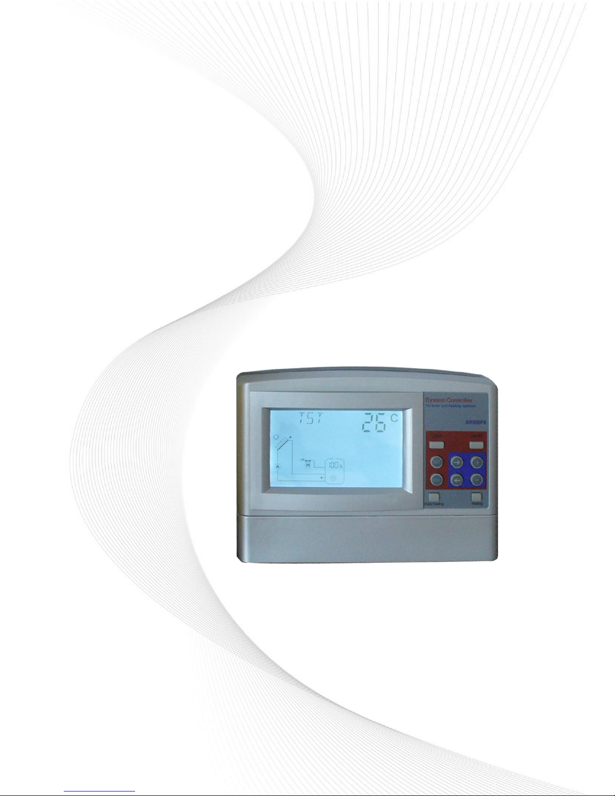
Controller for Solar Hot Water Project
Installation and Operating Manual
SR530F8 User Manual
Please read this manual carefully before using!

SR530F8 user manual
- 1 -
Content
1. Safety information .................................................................................................................. 3
1.1 Installation and commissioning ......................................................................................... 3
1.2 About this manual ................................................................................................................ 3
1.3 Liability waiver ...................................................................................................................... 3
1.4 Description of symbols ....................................................................................................... 4
2. Controller Installation ............................................................................................................ 4
2.1 Installing controller .............................................................................................................. 4
2.2 Wire arrangement ................................................................................................................ 4
2.3 Installing the pressure water level transmitter ................................................................. 5
2.4 Installing electropolar water level transmitter .................................................................. 6
2.5 Terminal connections .......................................................................................................... 6
2.6 Advice regarding the installation of temperature sensors ............................................. 7
3. Commissioning ...................................................................................................................... 8
3.1 Set time/week ...................................................................................................................... 8
3.2 Menu structure ..................................................................................................................... 9
3.3 Menu description ............................................................................................................... 10
4 System description ............................................................................................................... 11
5.Function description and parameters setup ................................................................... 12
5.1 Access the main menu ..................................................................................................... 12
5.2 DT Temperature difference .............................................................................................. 13
5.3 HIGH High、Middle、Low water position level setup ................................................. 14
5.4 TEMP Temperature main menu ...................................................................................... 14
5.4.1 CFR frost protection of collector .................................................................................. 15
5.4.2 SMX1 Maximum temperature of storage .................................................................... 16
5.4.3 CMN low temperature protection of collector............................................................. 17
5.4.4 WT1 Water Loading Temperature................................................................................ 17
5.4.5 MAX1 Maximum switch off temperature of floor heating (for heat transferring
between storage and heating return) .................................................................................... 18
5.4.6 MIN1 Minimum switch on temperature of storage (for heat transferring between
storage and heating return) .................................................................................................... 19
5.4.7 AH1O Switch-on temperature for self-heating tape .................................................. 19
5.5 FUN Auxiliary function ...................................................................................................... 20
5.5.1 CIRC Switch-on/off control of hot water circuit pump ............................................... 20

SR530F8 user manual
- 2 -
5.5.2 WMOD Water loading mode......................................................................................... 21
5.5.3 STYP selecting the type of the water level sensor.................................................... 22
5.5.4 OVER anti overflow protection function (optional) .................................................... 23
5.5.5 AUX Temperature difference control function for floor heating ............................... 23
5.5.6 AHEA Switch-on/off control of back-up heating system ........................................... 24
5.6 tHEA Timing heating ......................................................................................................... 25
5.7 tWAT Timing Water Loading ............................................................................................ 28
5.8 tCYC Time or Temperature controlled DHW pump ...................................................... 31
5.9 tIMO Timer function ........................................................................................................... 36
5.10 HND Manual mode ......................................................................................................... 38
5.11 PASS Password setting .................................................................................................. 39
5.12 RSET Recovery factory setting ..................................................................................... 40
5.13 On/OFF button ................................................................................................................. 40
5.14 Manual heating ................................................................................................................ 41
5.15 Manual Water Loading ................................................................................................... 41
5.16 Temperature check ......................................................................................................... 42
6. Protection function ............................................................................................................... 42
6.1. Memory protection ........................................................................................................... 42
6.2 Screen protection .............................................................................................................. 42
7. Trouble shooting .................................................................................................................. 42
7.1 Trouble protection .............................................................................................................. 42
7.2 PT1000/NTC10K resistance value ................................................................................. 43
8. Quality Guarantee ............................................................................................................... 44
9. Technical data ...................................................................................................................... 44
10. Delivery scope ................................................................................................................... 45
Appendix1: (SR530F8 type B) .................................................................................... 45

SR530F8 user manual
- 3 -
1. Safety information
1.1 Installation and commissioning
When laying cables, please ensure that no damage occurs to any of the constructional
fire safety measures presented in the building.
The controller must not be installed in rooms where easily inflammable gas mixtures
are present or may occur.
The permissible environmental conditions can’t be exceeded at the site of installation.
Before connecting the device, make sure that the energy supply matches the
specifications that controller requires.
All devices connected to the controller must conform to the technical specifications of
the controller.
All operations on an open regulator are only to be conducted cleared from the power
supply. All safety regulations for working on the power supply are valid.
Connecting and /or all operations that require opening the regulator (e.g. changing the
fuse) are only to be conducted by specialists.
1.2 About this manual
This manual describes the installation, function and operation of a solar thermal controller.
When installing the remaining components e.g. the solar collectors, pump assemblies and
the storage unit, are sure to observe the appropriate installation instructions provided by
each manufacturer. Only trained professional personnel may only perform installation,
electrical connection, commissioning and maintenance of the device. The professional
personnel must be familiar with this manual and follow the instructions contained herein.
1.3 Liability waiver
The manufacturer cannot monitor the compliance with these instructions or the
circumstances and methods used for installation, operation, utilization and maintenance of
this controller. Improper installation can cause damages to material and person. This is the
reason why we do not take over responsibility and liability for losses, damages or cost that
might arise due to the improper installation, operation or wrong utilization and maintenance
or that occurs in some connection with the aforementioned. Moreover we do not take over
liability for patent infringements or infringements – occurring in connection with the use of
this controller- on third parties rights. The manufacturer preserves the right to put changes
to product, technical date or installation and operation instructions without prior notice. As
soon as it becomes evident that safe operation is no longer possible (e.g. visible damage).
Please immediate take the device out of operation. Note: ensure that the device cannot be
SR530F8 user manual
- 4 -
accidentally placed into operation.
1.4 Description of symbols
Safety instruction:
The safety instructions in the manual are marked with a warning triangle. They
indicate measures, which can lead to personal injury and safety risks.
Operation steps: small triangle “►”is used to indicate operation step.
Notes: Contains important information about operation or function.
2. Controller Installation
Controller can only be installed indoors, far away from dangerous place and away from the
electromagnetic field.
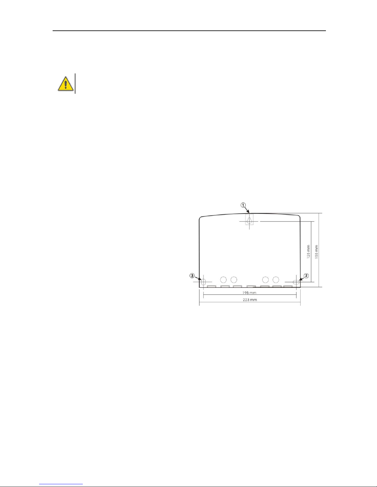
2.1 Installing controller
Note: the controller can only be mounted in
an area having an adequate level of
protection.
► Determine the mounting site of
controller.
► Drill the upper fixing hole on the wall.
► Fasten a screw.
► Move the terminal cover.
► Hang the base plate on the position ①
(showed in picture).
► Mark the position of 2 bottom holes ② ③.
► Remove the base plate.
► Drill the bottom fixing hole.
► Rehang the base plate on the screw ①.
► Fasted screw on ② ③ and fix base plate..
2.2 Wire arrangement
Depending on the type of installation, the cables may enter the controller through the rear
hole of the case ④or the lower side hole of the case.
Cable comes from the rear hole ④: Remove the plastic flaps ⑤ from the rear side of the
case using an appropriate tool.
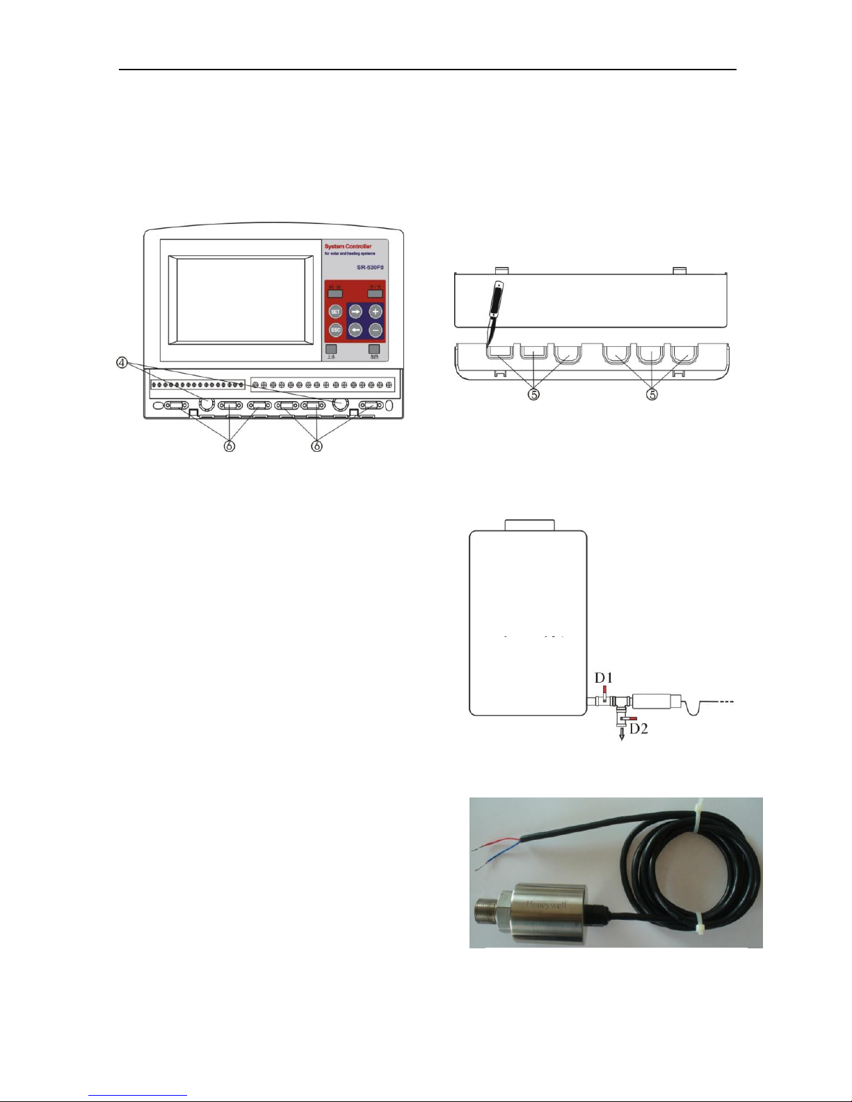
SR530F8 user manual
- 5 -
Cable comes from the below hole: Cut the left and right plastic flaps using an
appropriate tool (e.g. knife) and break them out of the case.
Notes: the flexible wire must be fixed on the case using the clamps ⑥ provided with
controller.
2.3 Installing the pressure water level transmitter
►Wrap some sealed tape on the sensor
connector of water storage, insert sensor into
the connector of the water storage, fasten the
copper connector and screw the sensor clock
wisely, fasten it on the connector, see left
picture.
►Connect the sensor cable with controller, and
note the polarity of wire (red wire for positive
polarity, blue wire for negative polarity).
►Mount the sensor at place where is vented,
dry, no corrosion and shady possibile, water
immersing and moisture in the terminal of
transmitter cable is forbidden.
►Switch-on power to controller, open the
drainage valve D2, and wait until water flows out
from D2 continuously, then close the valve D2.
Note:
Mounting a valve D1 /D2 between pressure
transmitter and water storage for easy maintenance.
Sample of pressure transmitter
Water storage
Pressure
transmitter
Wire
Mounting the pressure water level transmitter
SR530F8 user manual
- 6 -
Using Honeywell water level transmitter in the controlling system. (Red wire connected
on “+”polarity, blue wire connected on “-”polarity).
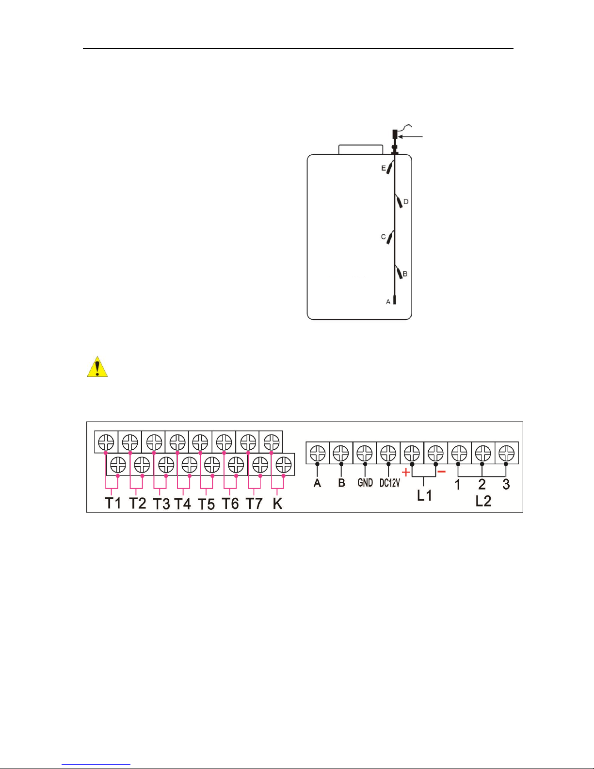
2.4 Installing electropolar water level transmitter
Connection the electropolar water level
transmitter:
Red wire of the three wires – connect L2
port 1
White wire of the three wires – connect L2
port 2
Black wire of the three wires – connect L2
port 3
2.5 Terminal connections
Before to open the terminal, please be sure to switch-off the power and pay
attention to the local electricity supply rules.
Input ports
1) Input T1 for PT1000 temperature sensor, temperature resistance ≤500OC
2) Input T2、T3、T4、T5、T6、T7 for NTC10K,B=3950 temperature sensor, temperature
resistance ≤135OC
3) Input k:for floating device(anti overflow protection)
4) L1 for pressure water level transmitter:
Water level height is less than (≤) 2.5 meter, red wire connect to “+” polarity, black
wire connect to “-” polarity,
Note not reversed the wire polarity.
5) L2 for electropolar water level transmitter:
Electropolar water
level sensor
Water storage
A、B、C、D、E Electro polar
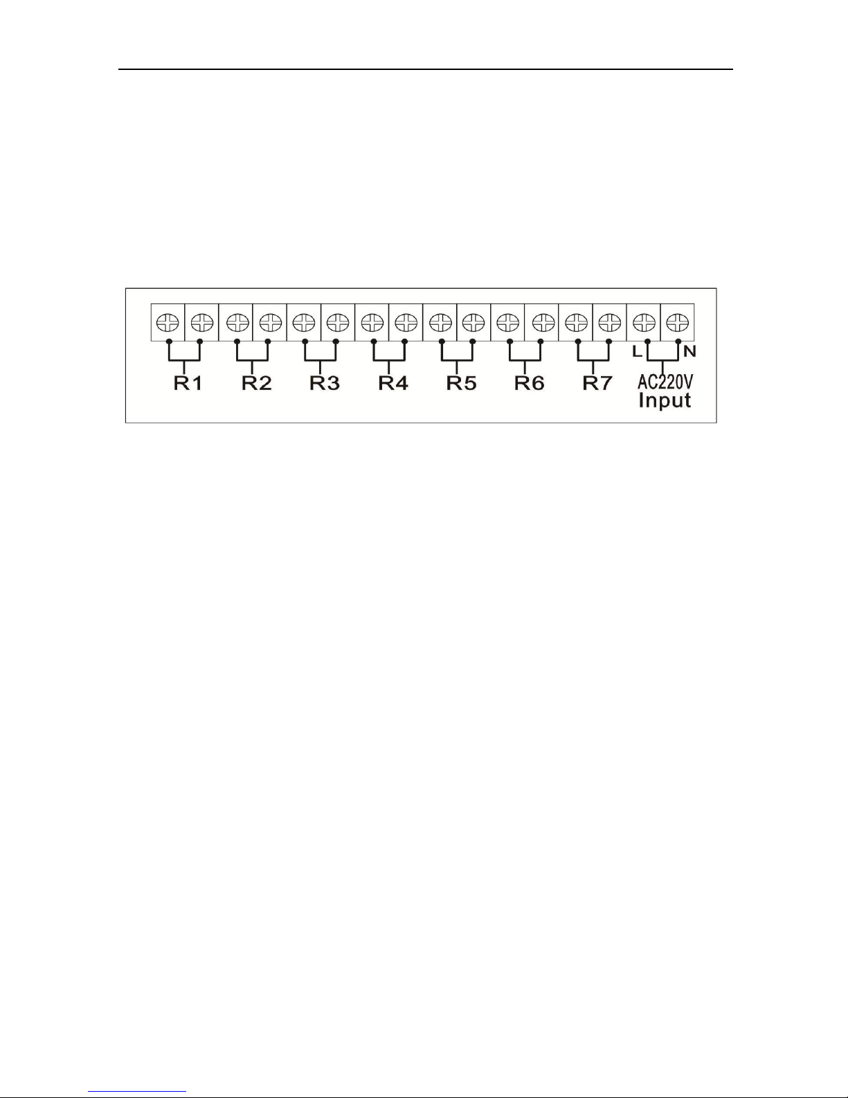
SR530F8 user manual
- 7 -
Port 1:Connect the red wire
Port 2:Connect the white wire
Port 3: connect the black wire
6) Communication Port : Remote control wires connects with A 、 B 、 GND
correspondingly.
Output ports
1) For power connection:"L" is live wire,"N" is naught wire.
2) Output ports R1、R2、R3、R4、R5、R6、R7 are electromagnetic relays, maximum
switch-on current: 5A.
2.6 Advice regarding the installation of temperature sensors
Only original factory enclosed Pt1000 temperature sensors are approved for use with
the collector, it is equipped with 1.5meter silicon cable and suitable for all weather
conditions, the temperature sensor and cable are temperature resistant up to 280 oC,
not necessary to distinguish the positive and negative polarity of the sensor
connection.
Only original factory enclosed NTC10K,B=3950 temperature sensors are approved for
use with tank and pipe, it is equipped with 1.5meter PVC cable, and they are
temperature resistant up to 105
o
C, not necessary to distinguish the positive and
negative polarity of the sensor connection.
Sensor cables may be extended to a maximum length of ca. 100 meter, when cable’s
length is up to 50m, and then 0.75mm
2
cable should be used. When cable’s length is
up to 100m, and then 1.5mm2 cable should be used.
All sensor cables carry low voltage, and to avoid inductive effects, must not be laid
close to 230 volt or 400-volt cables (minimum separation of 10cm)
SR530F8 user manual
- 8 -
If external inductive effects are existed, e.g. from heavy current cables, overhead train
cables, transformer substations, radio and television devices, amateur radio stations,
microwave devices etc, then the cables to the sensors must be adequately shielded.
3. Commissioning
Connect the sensors, pumps or switching valves to the controller before you
switch-on the power supply! After switching on power to the controller, firstly it will
ask for to set the time of controller.
3.1 Set time/week
►Press “Clock” button, time displays on the screen, hour selection area “00” blinks on the
display screen.
►Press “+/-” button to set hour of clock
►Press “Clock” button again, Minute area“00”blinks
►Press “+/-” button, to set minute of clock.
►Press “Clock” again, week area “WE” blinks
►Press “+/-” button, to set week.
After setting and wait for 6 seconds to save the parameter automatically. Current time and
week are displayed on the controller.
Code
Weekday
MO
Monday
TU
Tuesday
WE
Wednesday
TH
Thursday
FR
Friday
SA
Saturday
SU
Sunday
SR530F8 user manual
- 9 -
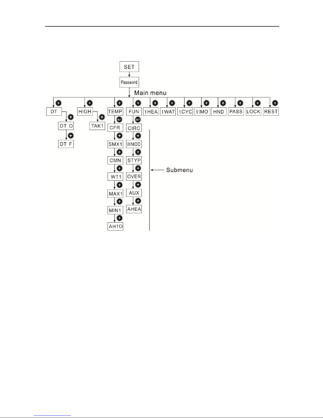
3.2 Menu structure
Submenu:
Through submenu, user can set the parameter as desired value, please check it carefully.
SR530F8 user manual
- 10 -
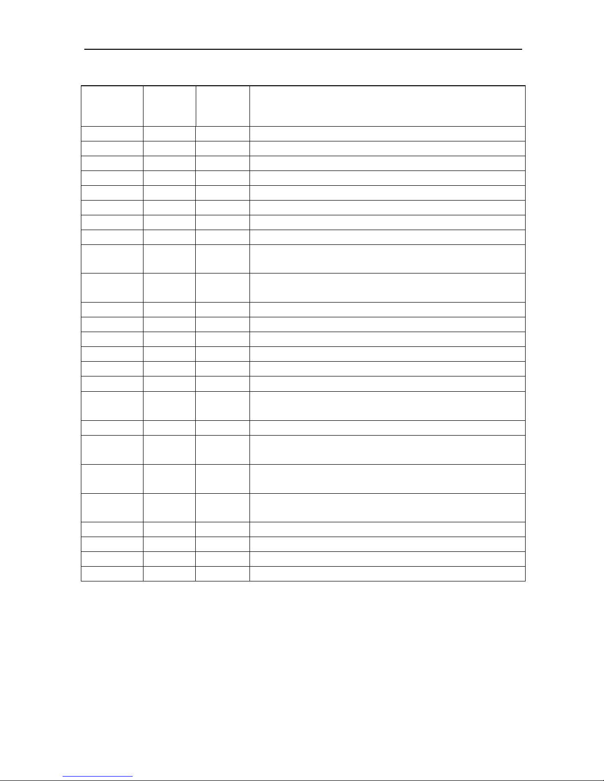
3.3 Menu description
Code
(Main
menu)
Code
Code
Menu Description
DT
DT O
Switch-on temperature difference
DT F
Switch-off temperature difference
HIGH
TAK1
Water height setting of storage 1
TEMP
For set relevant temperatures
CFR
Frost protection of collector
SMX1
Maximum temperature of storage
CMN
Low temperature protection of collector
WT1
Water loading Temperature
MAX1
Maximum switch off temperature of floor heating (for
heat transferring between storage and heating return)
MIN1
Minimum switch-off temperature of storage ( for heat
transferring between storage and heating return)
AH1O
Switch-on temperature for self-heating tape
FUN
Auxiliary functions
CIRC
Switch-on/off controlling of hot water circuit pump
WMOD
Water loading mode
STYP
Type of water level transmitter
OVER
Anti-overflow protection(optional)
AUX
Temperature difference controlling function for floor
heating
AHEA
Switch-on/off controlling of back-up heating system
tHEA
Setting the three time sections to control back-up
heating
tWAT
Setting the six time sections to control storage water
loading
tCYC
Setting the six time sections and temperature to control
hot water circuit pump
tIMO
Three time sections setting ( timer function)
HND
Manual control
PASS
Password setting
REST
Recovery to factory set
SR530F8 user manual
- 11 -
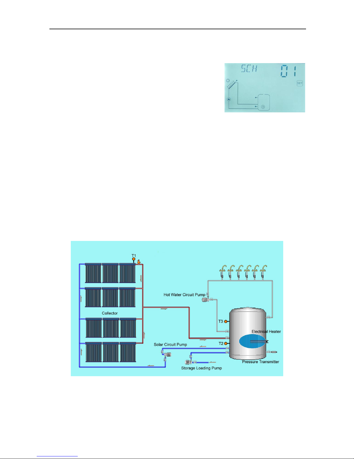
4 System description
System description:
Controller compares the temperature between collector
(T1)and storage(T2)( bottom part), if the temperature
difference(DT)rises up to the preset switch-on DT(DT
on
)
or is over it, circuit pump R1 is triggered ; and storage is
heated until DT drops to the switch-off DT(DT
off
) or when the storage temperature(T3)rises
up to its preset maximum temperature, then circuit pump R1 is ceased.
Back-up electrical heating control (Operation see paragraph 6.7)
Within a preset heating time section, if the storage temperature (T3) drops below the
switch-on temperature of heating, then back-up electrical heating (R5) is triggered; when
temperature T3 rises up to the switch-off temperature, then R5 is switched-off.
Storage water loading control:
When water height is below the minimum water height, the water loading pump R4 is
triggered to load water until water height rises up to the middle height, then pump R4 stops.
Note: T3 is an optional sensor, when no T3 sensor is installed in the system (no connection
to input port); controller will use the signal of temperature T2 automatically to control the
back-up heating or circulation.
SR530F8 user manual
- 12 -
Inputs and outputs definition:
Sensor
Description
Output
relay
Description
T1
Sensor on the collector
R1
For solar circuit pump 1
T2
Sensor on the bottom part of storage 1
R2
For floor heating output
T3
Sensor on the upper part of storage
1(optional)
R3
For hot water output
T4/T5
Sensor on floor heating pipe for
temperature difference control
R5
For electrical back-up
heater
T6
Sensor on hot water pipe
R4
For storage loading pump
T7
Sensor for triggering self heating tape
R6
For self auto heating tape
R7
For timer output
After system installation and before setting parameter, firstly to access main menu
and select “RSET” menu to recovery all parameter’s value to factory set value, and then
set value of parameters user desired.
5.Function description and parameters setup
5.1 Access the main menu
Under standby status,
►Press “SET” button, “PWD 0000” appears, and the left digital blinks, ask for entering
current password, factory set is “0000”
►Press “+/-” button to enter the first digital
►Repress “SET” button, the second digital blinks
►Press “+/-” button to enter the second digital
►Repress “SET” button, the third digital blinks
►Press “+/-” button to enter the third digital
►Repress “SET” button, the fourth digital blinks
►Press “+/-” button to enter the fourth digital
Note: the factory set password is “0000”, if no new password is set, then just press “SET”
SR530F8 user manual
- 13 -
four times to access main menu.
5.2 DT Temperature difference
Description:
Solar circuit pump R1 is triggered by the temperature difference function, so long as the
temperature difference between collector and storage reaches the switch-on DT, solar
circuit pump is triggered.
For example: the switch-on DT is 8oC, switch-off DT is 4oC, if the temperature on the
bottom part of storage is 20oC, then just when collector temperature rises up to 28oC, pump
is triggered, and when collector temperature drops to 24oC, pump is ceased.
Note: the switch-on/off DT of 8 oC and 4 oC are standard system setting according to many
years’ experience, only in special application cases it needs to be changed, (e.g. longer
distance heat transferring), normally we recommend using default set. Switch-on and
switch-off DT are alternating set. To avoid mistake the minimum difference between two
temperature differences (ΔTon –ΔToff) is set as 2 oC.
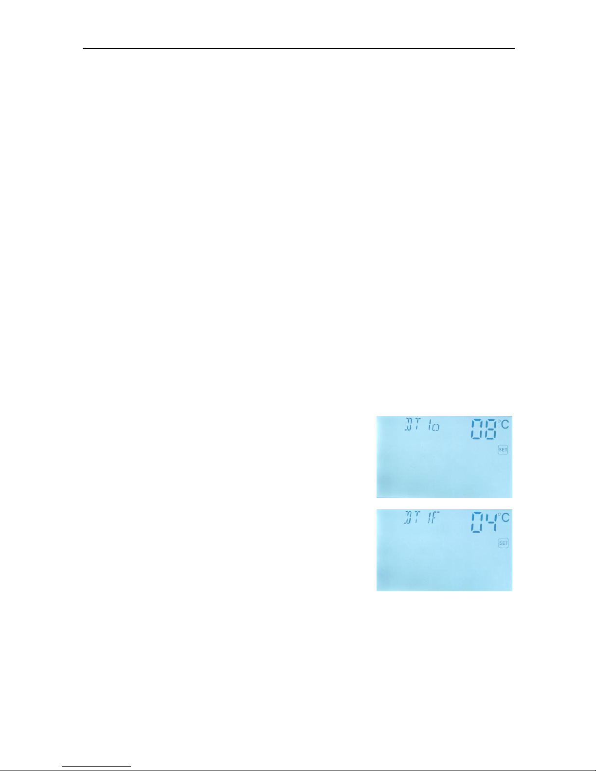
Setup temperature difference:
Under standby, access main menu DT
►Press “SET” button, to access settings program of main
menu DT, “DT 1o 08 oC” displays on screen, “08 oC” blinks,
the first switch-on temperature difference can be set.
►Press “+/-” button, to adjust the value of switch-on DT,
adjustable range (OFF+2 oC)~20 oC, factory setting is 8 oC
►Press “ESC” button to exit this setting, parameter is
saved automatically.
►Press “+” button, “DT 1F 04 oC” displays on the screen,
the first switch-off temperature difference can be set.
►Press “SET” button, “04 oC” blinks
►Press “+/-”button to adjust the value of switch-off DT, adjustable range 0 oC~( ON-2 oC),
factory set is 4 oC.
►Press “ESC” to exit menu, or wait for 20 seconds to exit automatically, the setup
parameters are saved automatically.
 Loading...