


Installation Instruction
Heatshrink Termination For 3 Core
Pilc Belted Cables 12kV
! PLEASE READ INSTRUCTIONS THOROUGHLY BEFORE PROCEEDING
! INSTALLATION SHOULD BE CARRIED OUT BY A TRAINED COMPETENT
FITTER
INDOOR
OUTDOOR
UNITS P1-P3 GROVEMERE COURT BICTON INDUSTRIAL PARK KIMBOLTON CAMBS PE28 OEY
TEL: +44 (1480) 861001 FAX: +44 (1480) 861002 E-MAIL: info@shrinkpolymersystems.co.uk
WEBSITE: www.shrinkpolymersystems.co.uk
©
General Fitting Instructions
CONNECTION
TYPE
LENGTH INDOOR
L
LENGTH OUTDOOR
L
X
STRAIGHT
CONNECTION
650mm 650mm
LENGTH OF
BARREL
CROSSED
CONNECTION
700mm
NOT
APPLICABLE
+ 10%
! It is highly recommended that suitable tools are utilised for the
correct preparation on Paper Cables
! Use a propane gas torch with a soft flame
! Avoid a pencil like blue flame which is caused by unregulated supply
! Keep the flame on the move to ensure even shrinkage of all the
materials and also helps to reduce scorching
! Ensure that all components are kept clean and grease free during
installation
! Allow to cool before applying any mechanical strain
Remove Outer Cable Sheath:
Table 1
Alternative tail lengths available upon request.
Note:- If T erminations are being applied to Armoured Cable, User may wish to use the ‘Bolt
On’ Heatshrink type cylinder Gland kit. See Instructions supplied with Gland.
Glands Available
SPS 318 16-70mm Pilc Cable SPS 452 35-185mm Picas Cable
SPS 319 95-150mm Pilc Cable SPS 453 240-400mm Picas Cable
SPS 320 185-300mm Pilc Cable
22
22
2
Improved Clearance/Cross Core Kit
A kit is available which converts Paper Belted Cable into a Screened Cable which enables
greater clearances between Cores and allows a Core Cross if required.
SPS 946 70-400mm
IMPORTANT NOTICE TO PURCHASER:- Sellers and Manufacturere’s only obligation shall be to replace such quantity of the product proved to be defective. Neither the Seller nor
Manufacturer shall be liable for any injury, loss or damage, direct or consequential, arising out of the use or inability to use the product. Before using, User shall determine the
suitability of the product for his or her intended use and User assumes all risk and liability whatsoever in connection therewith.
2
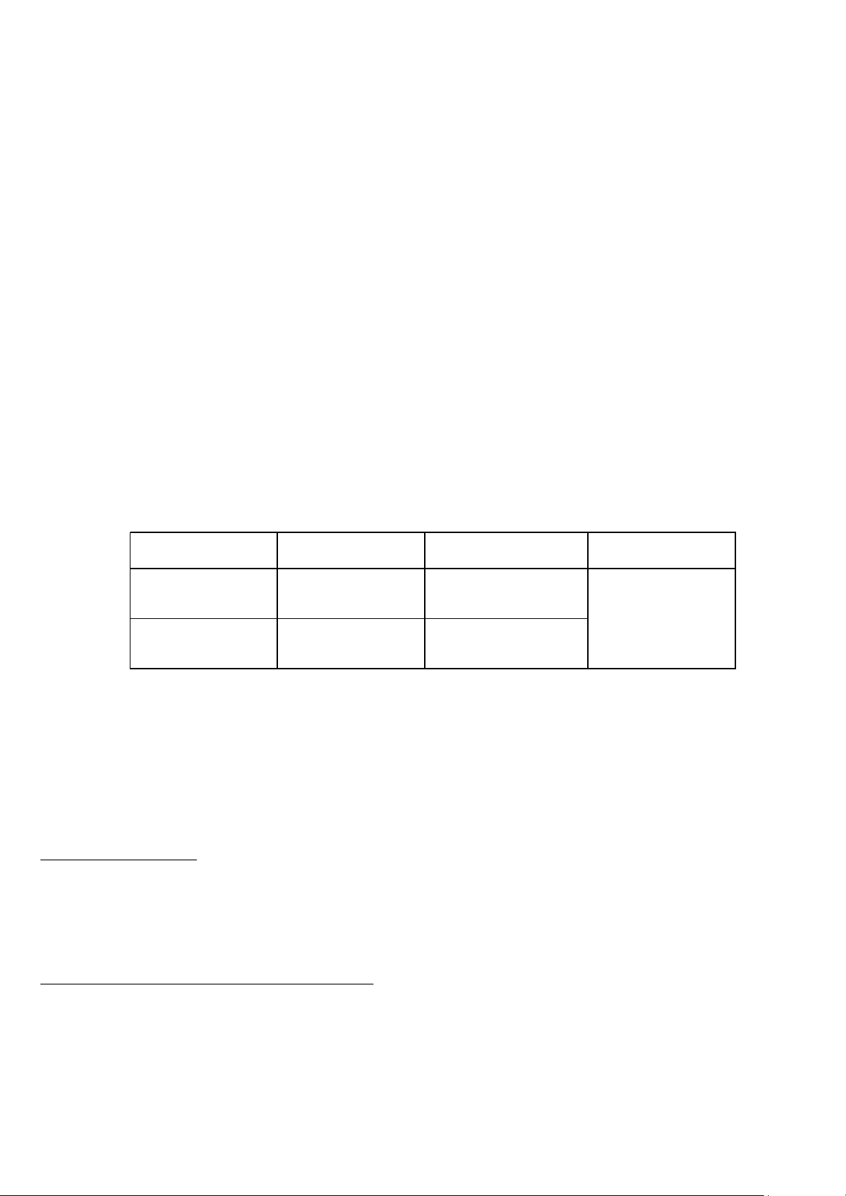
CORES
LEAD OR
ALUMINIUM
SHEATH
ARMOUR
WIRES
1. Installation
Prepare the Cable to the dimensions
shown in Fig 1 (For dimension L see
Table 1).
Expose the armour wires to 50mm for
plumbed connections. De-grease and
clean the Lead or Corrugated Aluminium
sheath and armour wires.
SHRINK
TUBE
L
100mm
150mm
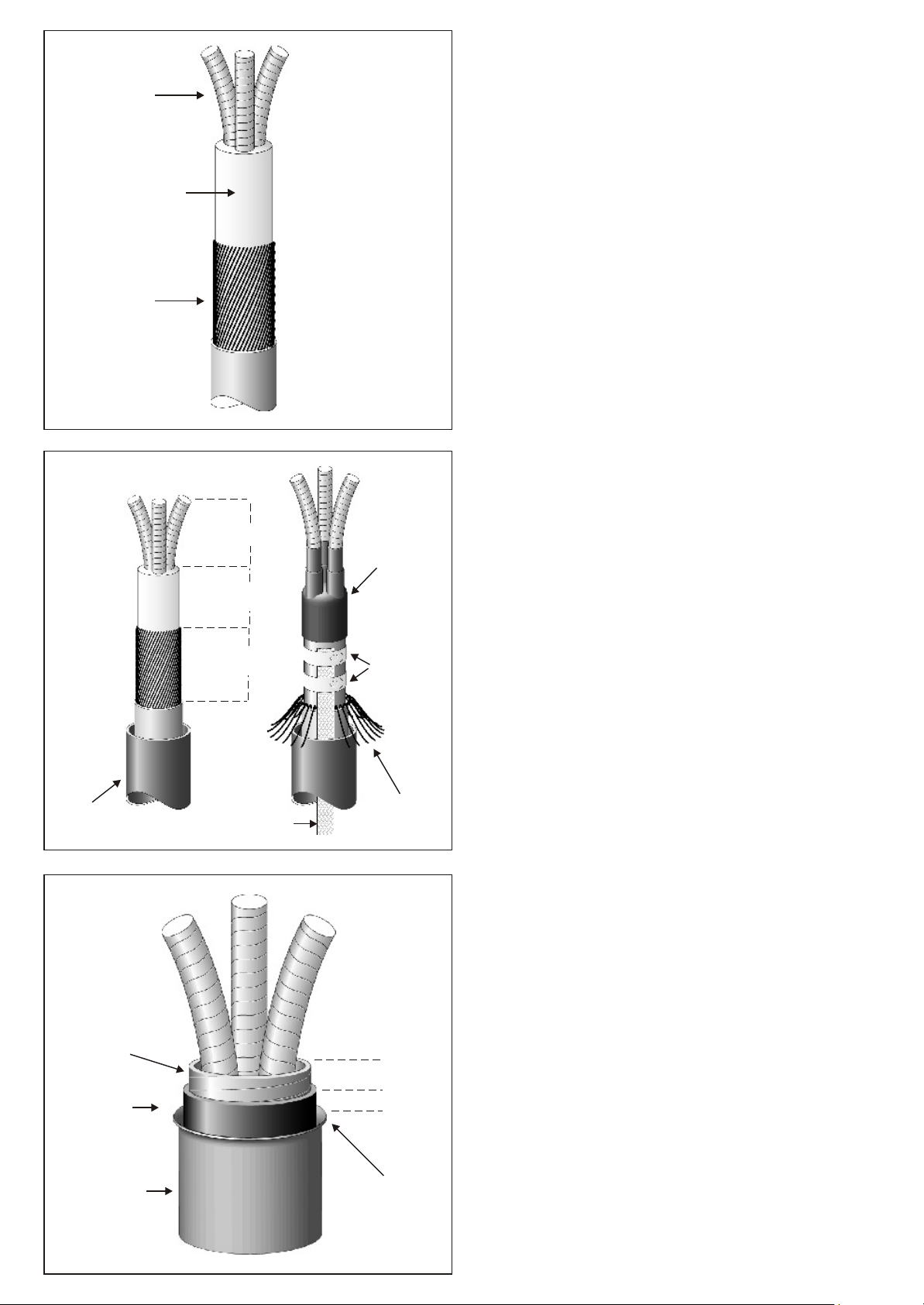
EARTH BRAID
BREAKOUT
BOOT
ROLL
SPRINGS
ARMOUR
WIRES
Mechanical Earthing Option
If using the Heatshrink ‘Bolt On’ Gland
with solderless earthing, prepare Cable to
dimensions shown. Note:- User may wish
to adjust these dimensions so that the
Breakout Boot fits down within the Gland
Body.
See separate instruction sheets for Pilc
and Picas Earthing using ‘Bolt On’ Gland
with Roll Spring (Lead) and Clamp System
(Picas).
2. Belted Cable Preparation
BELT
PAPERS
CARBON
PAPERS
LEAD OR
ALUMINIUM
SHEATH
20mm
5mm
BELL THE
LEAD
SHEATH
Expose the Lead or Aluminium Sheath to
a dimension of 250mm from the outer
Cable Sheath.
Unwind the Black Carbon Paper and
remove to a binder positioned 5mm from
the Metal Sheath cut.
Using a further binder, remove the Belt
Papers to 25mm from the Metal Sheath
cut.

CLEAR SHRINK
SLEEVES
Fitting the Clear Shrink Sleeves
With a clean dry cloth, carefully remove
any Grease from the Cores.
Position the Clear Shrink Sleeves over
each Core approx 50mm up from the
Cable Crutch. With a suitable heat sourse,
shrink the end’s of the Sleeves for about
50mm, before fully shrinking, rotate the
Sleeves and push down into the Crutch.
Note: E
nsure there are no air voids and
the Sleeves are wrinkle free, also note
that excessive heat may dry out and
damage the Paper Insulation.
Fitting the Stress Control Tubes
50mm
STRESS
CONTROL
TUBE
Position the Stress Control Tubes onto the
Cores at a distance of 50mm up from the
Metal Sheath Cut.
Shrink the Tubes one at a time, starting
from the bottom working upwards. Ensure
that the Tubes are evenly shrunk and
aligned.
Cable Crutch Preparation
MASTIC
CRUTCH
WEDGE
Remove the Grey Mastic Crutch Wedge
from its container and insert well down
into the Cable Crutch so that any Air gaps
are eliminated.

10mm
10mm
LEAD OR
CAS SHEATH
With tension, wrap the Grey Mastic Tape
around the Crutch area and overlap the
Stress Control Tubes and Lead or
Aluminium Sheath by approx 10mm.
Note:- Ensure that the space between the
Bell of the Lead Sheath and the entire
area between the Cores is fully covered by
the Mastic tape to eliminate Air Voids.
With a suitable solvent, clean the Metal
Sheath before proceeding.
3. General Cable Preparation
Installing the Breakout Boot
SEMI-CONDUCTIVE
BREAKOUT BOOT
X
Slide the 3 Leg Semi-Conductive Breakout
Boot down the Cores and press firmly
down into the Crutch.
The Legs of the Boot should be in contact
with the Stress Control Tubes and the
Skirt should cover the Grey Mastic Tape
and make contact with the Lead or
Aluminium Sheath.
Shrink the Boot from the centre to one
end at a time. The Boot may need to be
held in place during installation.
4. Installing Cable Lugs
Allowing for dimension X (Lug Barrel +
5mm), cut the Cores to suit the fixing
point on the equipment being used.
L + 200mm
Measure a distance of X (See Table 1)
back from the end of each Core and
remove Insulation.
With a suitable tool, install Cable Lugs
ensuring that any sharp points are
removed.
Note:- Where Mechanical Connectors are
to be used, user should check that the
Core Tubes are able to slide over prior to
fitting.

DISTANCE (d) PHASE/PHASE TOP OF STRESS TUBE
& PHASE/GROUND TO LUG BARREL
VOLTAGE d (mm) E
7.2kV 15mm 30mm
12kV 20mm 50mm
17.5kV 20mm 75mm
24kV 25mm 95mm
36kV 40mm 250mm
NUMBER OF SHEDS PER PHASE
VOLTAGE INDOOR OUTDOOR
7.2kV - 1
12kV - 1
17.5kV - 1
24kV - 2
36kV 1 3
ANTI-TRACK
TUBE
RED SEALANT
TAPE
5. Installing Anti-Track Tube
Preheat each Cable Lug and wrap two
layers of Red Sealant Tape over the Lug
Barrel extending onto the Insulation by
approx 10mm.
Also apply a turn of Red Sealant around
the tops of the Breakout Boot fingers.
Position the Anti-Track Core Tubes so that
they cover the Fingers of the Breakout
Boot and the Barrels of the Lugs.
Shrink the Tubes starting from the bottom
towards the top. Keep the flame on the
move to ensure an even wall thickness
and that the Tubes are wrinkle free. Allow
to cool to hand hot and trim at the Lug
end with a sharp knife if necessary.
AIR CLEARANCE REQUIRED
BY LOCAL SPECIFICATION
E
Indoor Terminations - Requirements
Table 2
d
Note:- Bushing protection boots will be
required for the majority of installations.
6. Installation Of Rain Sheds
r = SEE d DIMENSION
IN TABLE 2
A Strain Relief Shed is required for
Outdoor Terminations. This should be
fitted first by positioning it as low down as
possible but above the end of the
Breakout Fingers (Approx 60mm).
120mm
60mm
STRAIN RELIEF
SHED
Continue to install the appropriate number
of Rain Sheds in accordance with the
details shown in Table 3.
Table 3

All subsequent sheds should be fitted at a
distance of 80mm from edge to edge.
Note:- It is advisable not to position rain
sheds at the top of stress control tubes,
re-position if necessary.
If a termination is to be mounted for
connection above the equipment i.e in the
reverse position, sheds should be installed
through 180 as shown.
0
7. Core Crossing
Screened Cable
If the Cores on a Paper Screened Cable
have to be crossed, ensure that the cross
takes place within the screened area
below the Stress Control Tubes.
STRESS CONTROL
TUBES FITTED IN
A HIGHER POSITION
Belted Cable
Core crossing on Belted construction is
not recommended unless the minimum
clearances are achieved (See Table 2).
Note:- Core Crossing/Improved Clearance
kits utilising Heatshrink Conductive
Tubings can be supplied if requested.
 Loading...