

Page 1
INSTALLATION INSTRUCTION
HEATSHRINK JOINT TO SUIT SINGLE CORE 7.2-36kV
POLYMERIC CABLE TYPE SPAJ
©
DATE OF ISSUE: 26.11.03
Page 2
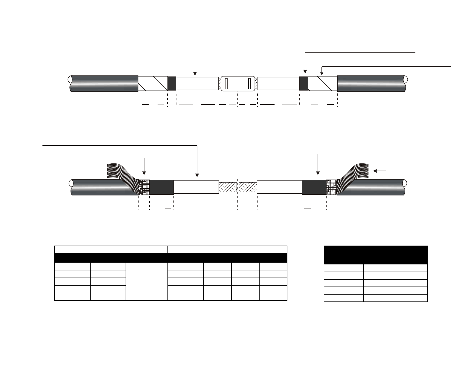
CABLE PREPARATION
SIZE
(mm2)
MAX CONNECTOR
LENGTH
16-35 100mm
50-95 110mm
120-185 150mm
240-400 220mm
500-1000 250mm
VOLTAGE TABLE HEATSHRINK TUBE REQUIREMENT
VOLTAGE A X TCC GMT GIS TMI
7.2kV 120mm HALF 1 --- 1 1
12kV 130mm CONNECTOR 1 --- 1 1
17.5kV 150mm LENGTH 1 1 1 1
24kV 170mm +5mm 1 1 1 1
36kV 220mm 1 2 1 1
COPPER TAPE SCREEN
OR LEAD SHEATH
EXTRUDED/SOLUBLE SCREEN
PRIMARY INSULATION
COPPER TAPE SCREEN OR LEAD SHEATH
Fig 1
80 15 A X X A 15 80
COPPER WIRE/COPPER BRAID SCREEN
PRIMARY INSULATION
BRAID ARMOUR IF PRESENT
EXTRUDED/SOLUBLE SCREEN
COPPER WIRES
TWISTED BACK
Fig 2
30 80 A
X 80AX 30
NOTE:- IN FIG 2, EXPOSE CABLE BY FURTHER 30mm ONLY IF BRAID ARMOUR IS PRESENT
FOR ALUMINIUM WIRE ARMOUR (AWA) SEE FIG 13-14
TCC = BLACK STRESS CONTROL TUBE GMT = RED INSULATION TUBE
GIS =INSULATION/CONDUCTIVE COMBINED TUBE TMI = OUTER SHRINK SEALING TUBE
Table 1
Table 2
Page 3

Cable Preparation
1. Ensure that the Cables overlap before proceeding.
Copper Tape Screen Or Lead Sheath
2. Expose the Copper Tape Screen or Lead Sheath by 80mm and the Black Semi-Conductive Screen by a further 15mm
beyond it (See Fig 1 and Table 1 for dimension A dependant on voltage class). If the Cable is Aluminium Wire Armoured
expose Armours by 40mm and Inner Bedding by 35mm (See section 22-24 and Fig 13-14).
Copper Wire Screen
3. Bend back the Wires onto the Outer Cable Sheath, these will be bonded at a later stage. Expose the Black
Semi-Conductive Screen by 80mm (See Fig 1 and T able 1 for dimension A dependant on voltage class).
Braided/Woven Copper or Phosphur Bronze Screen
4. If Cable has a Braided/Woven Copper or phosphur Bronz e Screen, expose this by 30mm (See Fig 2). Expose the Black
Semi-Conductive Screen by a further 80mm and the A dimension according to voltage class shown in T able 1.
Black Extruded Semi-Conductive Screen Removal
5. Remove the Black Screen layer using a suitable Tool. Avoid scoring and damage to the Primary Insulation beneath.
Note:- The Screen should be completely removed leaving a cleanly cut end. Do not roughen the Primary Insulation with
Emery cloth.
Screen removal Tools can be provided for both ‘Peelable’ and ‘Bonded’ Screen layers, see Shrink Polymer Systems
catalogue page 38.
Soluble Semi-Conductive Screen Layer
6. Using a Non-adhesive Tape, cover the top of dimension A and remove the Black Semi-Conductive soluble layer above
using a clean cloth and suitable solvent. Note:- Remove all traces of Carbon and remember to remove the Tape.
It is good practice to flame brush the Primary Insulation and Screen cut. This has the effect of removing any minor surface
scratches or burrs that may be present.
Nested Tube Sequence
GIS COMBINED
TUBE
GMT RED INSULATION TUBE/S
TCC STRESS CONTROL TUBE
7. Before proceeding, position the Connector Insulation
Tubes down one or both of the Cables ends if the Tubes do
not “Nest”as shown in Fig 3.
Note:- Picture shows one GMT Tube making the Joint suit-
GIS
GMT
able for 17.5 and 24kV. For 12kV, only TCC Stress Control
and GIS combined Insulation/Conductive Tubes are
required.
Fig 3
Page 4

Stress Relief
15
Fig 4
STRESS
TAPE
15
8. Remove the Primary Insulation for ½ length of the Connector + 5mm.
9. Crimp the Connector with the correct T ool/Die and remove any sharp burrs.
10. De-grease the Connector and Primary Insulation with the Tissues provided.
11. Apply the Yellow TS 31785Y Stress Tape over the Connector with half width overlap and
double stretch. Important:- Fill in the gap between Primary Insulation and Connector and
extend onto the Primary Insulation by 15mm only. If Reducer Ferrules are used to join
different Conductor sizes, ensure Stress Tape is “Tapered” from Connector to the
Insulation.
10mm
12. Stretch the Yellow TS 31785Y Stress Relief Tape to double its length and apply with ½
width overlap around each Black Semi-Conductive Screen edge so that it overlaps for a
15mm
distance of 15mm onto the Copper Tapes or Lead Sheath and the Primary Insulation by
10mm as shown in Fig 5.
Fig 5
Connector Insulation Tube Sequence
GIS
TCC
Fig 6
13. Position the Stress Control Tube (TCC) centrally over the
Connector overlapping the end of Screen points and onto the Copper
Tape Screens (If present) or Lead Sheath. With a suitable heat
source, shrink from the centre working all around the T ube to one end
at a time. Note:- Allow the Tube to cool before cleaning the surface
with the Tissues provided (This improves electrical performance).
14. If voltage is higher than 12kV position the required number of
Red GMT Tubes one at a time, centrally over the Stress Control T ube
and shrink in an even manner (See T able 1 for T ube requirement).
Fig 7
GIS
15.Position the Combined Insulation/Conductive Tube (GIS) centrally over the Stress Control Tube (Or Red GMT Tube depending on
voltage) and shrink as previous. Keep the flame on the move to
ensure an even wall thickness.
Page 5

4SC HV GREY TAPE
GIS
20
Fig 8
Screening - Copper Tape Screen
16. Take the two pieces of 4SC HV Grey Mastic Tape and apply
whilst stretching to the ends of the GIS Tubes and Copper Tape
Screens (If present) or Lead Sheath by approx 10mm each as
shown in Fig 8.
KM 50 COPPER
SCREENING BANDAGE
17. Wrap two layers of Copper Screening Bandage (KM 50) with
50% overlap over the Joint area and secure to the Copper Tape
DWHV
DWHV
Fig 9
SCT
ROLL SPRING
Screens or Lead Sheath by either Soldering or the preferred Roll
Spring method.
Screening - Copper Wire Screen
18. Wrap a layer of KM50 Copper Screening Bandage over the
joint area and secure. Bend the Copper Wire Screen back over
the Joint and twist the ends together to form a stranded
DWHV
Fig 10
SCT
BINDING WIRE
Conductor. Join the two Wire Screens with a Crimp Ferrule as
shown in Fig 10. Wrap a further layer of Screening Bandage over
the Joint and secure at each end with binding wire.
Screening - Copper/Phosphur Bronze Braid Screen
Fig 11
KM 50 COPPER
SCREENING BANDAGE
DWHV
DWHV
SCT
ROLL SPRING
BRAID SCREEN
19. Wrap two layers of Copper Screening Bandage (KM 50) with
50% overlap over the Joint area and secure to the
Copper/Phosphur Bronze Braid Screens by either Soldering or
the preferred Roll Spring method.
Page 6

Outer Sealing
OUTER SHRINK TUBE
20. Clean and De-grease the outer Cable Sheaths. Position the
Outer adhesive lined Shrink Tube centrally over the joint gap.
Start shrinking from the centre to one end at a time. Keep the
flame on the move to ensure an even wall thickness. The Tube
should be wrinkle free and Sealants should be visible at Tube
ends.
Fig 12
If Armour Earthing Required See Fig 13-14
212 D MASTIC TAPE
50 35
Fig 13
212 D MASTIC TAPE
21. Allow the completed Joint to cool before applying any
mechanical strain.
22. Fit the Armour Support Rings before wrapping the Heavy
Duty Aluminium Cage tightly around the joint gap. Secure to both
ends with the Clamps provided. Apply the remaining pieces of
212D Black T ape over the Clamps and any sharp points as shown
in Fig 14. Note: Depending on length of Connector used which
effects the joint gap, user may need to trim the Cage
24. Refer back to section 20 and Fig 12 for the installation of the
Outer Shrink T ube.
Fig 14
ARMOUR CAGE
©
IMPORTANT NOTICE TO PURCHASER:- Sellers and Manufacturere’s only obligation shall be to replace such quantity of the product proved to be defective. Neither the Seller nor
Manufacturer shall be liable for any injury, loss or damage, direct or consequential, arising out of the use or inability to use the product. Before using, User shall determine the
suitability of the product for his or her intended use and User assumes all risk and liability whatsoever in connection therewith.
UNITS P1-P3 GROVEMERE COURT BICTON INDUSTRIAL PARK KIMBOLTON CAMBS PE28 OEY
TEL: +44 (0) 1480 861001 FAX: +44 (0) 1480 861002 EMAIL: info@shrinkpolymersystems.co.uk WEB: www.shrinkpolymersystems.co.uk
 Loading...