

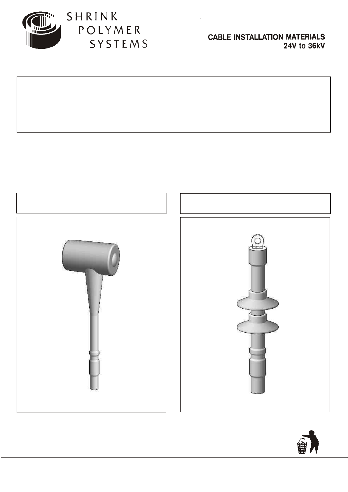
Installation Instruction
Heatshrink Termination For Single
Core Polymeric Cables 7.2kV to 36kV
* PLEASE READ INSTRUCTIONS THOROUGHLY BEFORE PROCEEDING *
INDOOR
OUTDOOR
UNITS P1-P3 GROVEMERE COURT BICTON INDUSTRIAL PARK KIMBOLTON CAMBS PE28 OEY
TEL: +44 (1480) 861001 FAX: +44 (1480) 861002 E-MAIL: info@shrinkpolymersystems.co.uk
WEBSITE: www.shrinkpolymersystems.co.uk
©
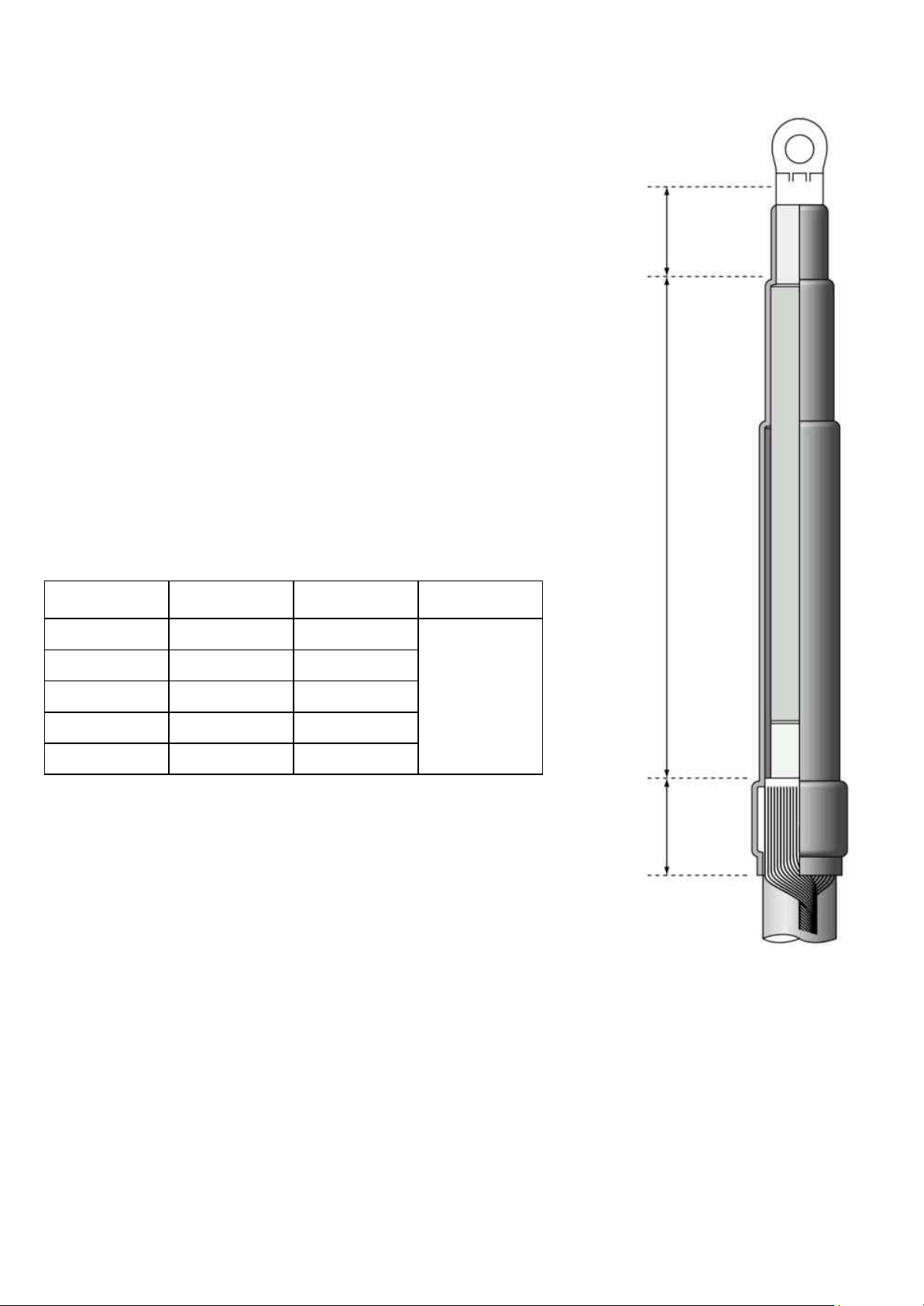
General Fitting Instructions
VOLTAGE
INDOOR
L
OUTDOOR
L
X
7.2kV 150mm 200mm
12kV 190mm 270mm LENGTH OF LUG
17.5kV 250mm 300mm BARREL + 10%
24kV 310mm 360mm
36kV 510mm 600mm
! It is highly recommended that a tool suitable
for the removal of the semi-conductive screen
is used to provide a reliable discharge free
termination screen point
! Use a propane gas torch with a soft flame
! Avoid a pencil like blue flame which is caused by
unregulated supply
! Keep the flame on the move to ensure even
shrinkage of all the materials and also helps to
reduce scorching
! Ensure that all components are kept clean and
grease free during installation
! Allow to cool before applying any mechanical
strain
Remove Outer Cable Sheath:
X
L
Table 1
Single Core Armoured Cables
If the Cable is Armoured, bonding of the Armours must be
completed
using the appropriate Armour Earthing kit.
A) For Indoor T erminations (Cable End Box) - Order Bolt On
Aluminium Earth Gland Ref: SPS 560*
B) For Outdoor Terminations (Pole Top) - Please advise
Conductor and Voltage rating.
* SPS 560 size range = 50-630mm2 7.2-36kV
IMPORTANT NOTICE TO PURCHASER:- Sellers and Manufacturere’s only obligation shall be to replace such quantity of the product proved to be defective. Neither the Seller nor
Manufacturer shall be liable for any injury, loss or damage, direct or consequential, arising out of the use or inability to use the product. Before using, User shall determ ine th e
suitability of the product for his or her intended use and User assumes all risk and liability whatsoever in connection therewith.
60
mm
Fig1

30mm
Fig 2
CONSTANT
FORCE
1. Installation
Remove the Outer Cable Sheath to the
dimensions L + X given in Table 1.
Remove any fillers before cleaning and
de-greaseing the Cable Sheath below.
2. Screen Treatment
Copper Wire Screen
Apply one turn of the Red Mastic Sealant
Tape at a point 30mm below the sheath
cut (Fig 2).
Bend back the Copper Wires and press
them into the Tape. Apply one more turn
of Red Mastic Tape over this point. The
Wires should be twisted together and
Bonded to a suitable earth point.
PRIMARY
INSULATION
40mm
RED
MASTIC
40mm
30mm
Fig 3
20mm
MOISTURE
BLOCK
CONDUCTIVE
LAYER
CONSTANT
FORCE
SPRING
Copper Tape Screen
Apply one turn of the red Mastic Tape at a
point 30mm below the sheath cut (Fig 3).
Remove the Copper Tape Screens to a
point 40mm above the Cable Sheath cut
as shown opposite in Fig 3.
Position a Copper Earth Braid onto the
Copper Screen and secure with a Constant
Force Roll Spring. Ensure the Moisture
Block in the Braid is bedded into the Red
Mastic and apply one more turn of Tape
over this point. Secure the end of the
Braid to a suitable Earth point.
Note:- A full range of Solderless Earth
Bonding kits are available for all Voltages
and Conductor sizes.
3. Conductive Layer Treatment
INSULATION
10mm
10mm
PRIMARY
Fig 4
Fig 5
Extruded Conductive Layer
Remove the Conductive layer using a
suitable Tool to the dimensions shown in
Fig 3 and 4. Avoid scoring and damage to
the Primary Insulation.
Note:- The Screen should be removed
leaving a cleanly cut end. Do not roughen
the Insulation with Emery Cloth.
STRESS
RELIEF
TAPE

STRESS
RELIEF
TAPE
10mm
Soluble Conductive Layer
Cover the Conductive screen with Non
adhesive Tape for 40mm on Wire
Screened Cables and 20mm on Copper
Tape Screened Cables (see Fig 4).
10mm
Fig 6
STRESS CONTROL TUBES
Remove the layer after this point with a
suitable solvent until totally clean.
Remember to remove the Tape when
finished.
4. Apply Stress Relief Tape
Remove the release paper, stretch the
TS31785Y Yellow Stress Tape to double its
length and apply around the end of each
Core Screen to cover Copper Tape(if
present) and Insulation by 10mm
(see fig 5,6).
5. Stress Control Tubes
Position the Stress Control Tubes so that
they cover the Earth connection point and
the Conductive Screen end. However do
not extend past this point onto the Outer
Cable Sheath.
Fig 7
L + X
Fig 8
RED SEALANT TAPE
Shrink the Tubes one at a time starting
from the bottom. Ensure the tubes are
wrinkle free and have an even wall thickness.
6. Installing Cable Lugs
The Cable should be cut to dimension L+X
as given in Table 1. Remove the Insulation
at X and install the Lug using the appro-
X
priate method.
Preheat each Lug and wrap two layers of
Red Sealant Tape over the Lug barrel and
extend onto the Insulation by approx
10mm. Ensure the Tape is applied as
shown.
Fig 9

NUMBER OF SHEDS PER PHASE
VOLTAGE INDOOR OUTDOOR
7.2kV - 2
12kV - 2
17.5kV - 2
24kV - 3
36kV 1 4
60mm
VOLTAGE (kV) 7.2 12 17.5 24 36
DIS TANCE (mm ) 15 20 20 25 35
ANTI-TRACK TUBE
Fig 10
7. Installing Anti-Track Tube
Position the Anti-Track Tubes so that they
overlap the Earth connection point and
outer Cable Sheath by 60mm as shown in
Fig 10.
Shrink the Tubes starting from the bottom
towards the top. Keep the flame on the
move to ensure an even wall thickness.
User may trim the Tubes at the Lug end
with a sharp knife if necessary.
8. Indoor Terminations
Anti-Track Rain Sheds are not required on
Indoor Terminations rated between 7.2
and 24kV. One Shed per phase is required
on 36kV types (see Table 2).
Table 2
Clearance Dimen ions
s
Minimum clearances should be observed
for phase to phase and phase to ground
(see Table 3).
Table 3
9. Outdoor Terminations
Anti-Track Sheds should be fitted starting
from the bottom up as per the dimensions
given in Fig 12.
The number of Sheds required depends on
the system voltage (see Table 2).
Fig 11
80mm
Fig 12
200mm
Positioning of Sheds
The first Shed should be fitted at a distance of 200mm from the lower edge of
the Anti-Track Tube to the edge of the
Shed. All subsequent Sheds should be
fitted at a distance of 80mm from edge to
edge.
Note:- It is advisable not to position
Sheds at the top of the Stress Control
Tubes. Re-position if necessary.

Fig 13
Min Bending Radius r=15xD
Reverse Connection
If a Termination is to be mounted for
connection above the equipment i.e in the
reverse position, Sheds should be
installed through 180º.
10. Cable Bending Radius
If required The Cable can be heated to
approximately 70ºC to enable a bend to
be introduced. See Fig 14 showing the
bending radius.
D
Fig 14
IMPORTANT NOTICE T O PURCHASER:- Sellers and Manufacturere’s only obligation shall be to replace such quantity of the product proved to be defective. Neither the Seller nor
Manufacturer shall be liable for any injury, loss or damage, direct or consequential, arising out of the use or inability to use the product. Before using, User shall determine the
suitability of the product for his or her intended use and User assumes all risk and liability whatsoever in connection therewith.
UNITS P1-P3 GROVEMERE COURT BICTON INDUSTRIAL PARK KIMBOLTON CAMBS PE28 OEY
TEL: +44 (1480) 861001 FAX: +44 (1480) 861002 E-MAIL: info@shrinkpolymersystems.co.uk
WEBSITE: www.shrinkpolymersystems.co.uk
©
 Loading...