

INSTALLATION INSTRUCTION
HEASHRINK JOINT TO SUIT 3 CORE 33kV
POLYMERIC CABLE TYPE SPAJ 36X
* THESE INSTRUCTIONS SHOULD BE FOLLOWED BY A TRAINED COMPETENT FITTER
* A PROPANE GAS TORCH IS THE PREFERRED METHOD FOR SHRINKING THESE MATERIALS
* ENSURE THAT THE MATERIALS ARE KEPT CLEAN AND DRY AND ARE FREE FROM DUST, SAND AND GREASE
* PLEASE CALL SHRINK POLYMER SYSTEMS FOR ANY ADVICE
©
DATE OF ISSUE:- 04.10.05
ALL DIMENSIONS SHOWN IN mm
SIZE
(mm2)
A B C D X
MAX CONNECTOR
LENGTH
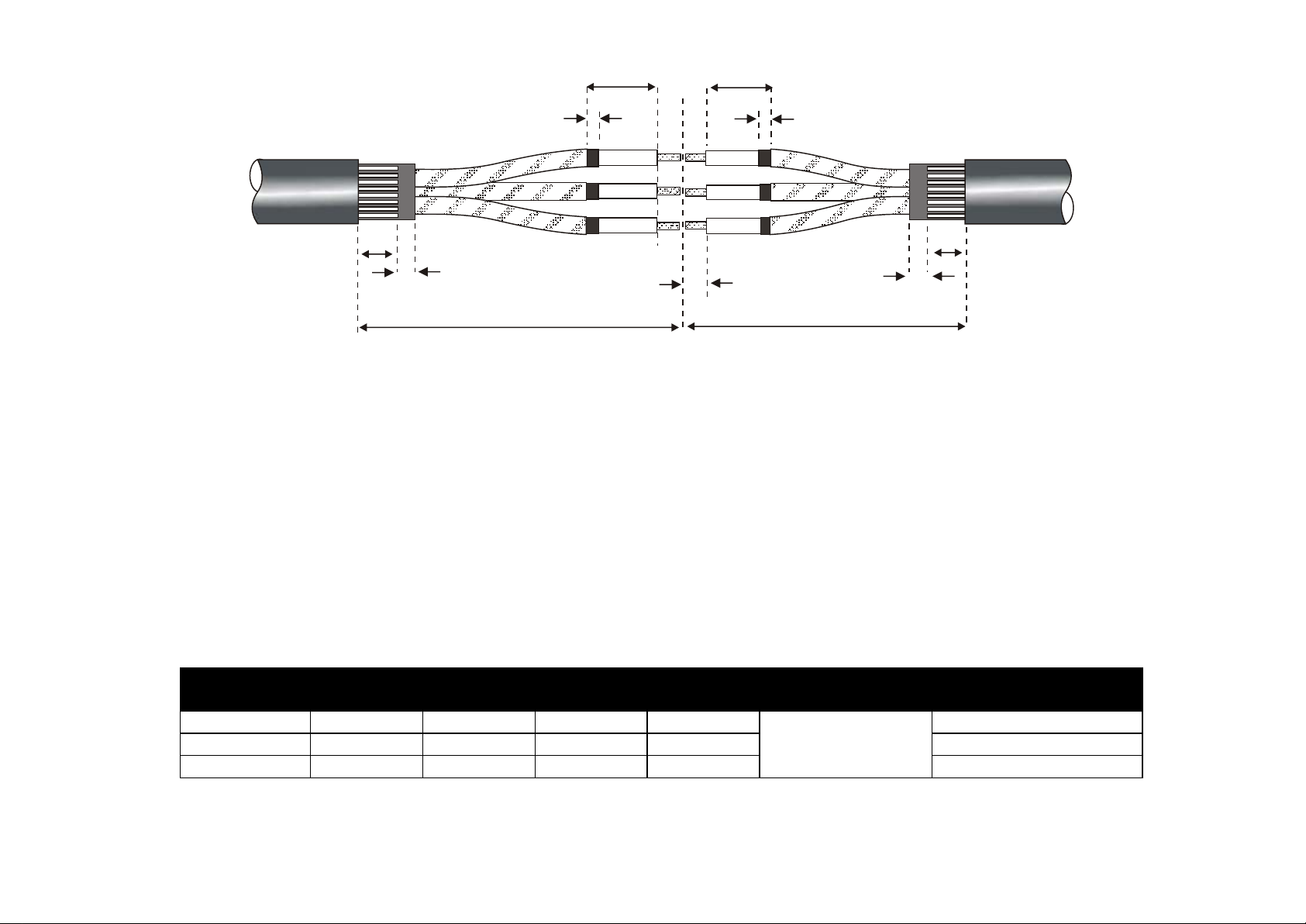
35-95 1200mm 750mm 220mm 220mm HALF LENGTH 110mm
120-185 1300mm 750mm 220mm 220mm CONNECTOR 150mm
240-300 1375mm 750mm 220mm 220mm +5mm
160mm
10
C
X
D
10
Fig 1
75
STRIP TO ½ LENGTH OF
30
CONNECTOR + 5mm
LONG SIDE (A)
X
+ 5mm
SHORT SIDE (B)
75
30
1. Ensure the Cables overlap before preparing to the dimensions above and in accordance with the Table below for
Conductor size.
2. Expose Armour to 75mm and Bedding to 30mm.
3. Remove Copper Tape Screens for a distance of 220mm + ½ Connector length + 5mm.
4. Remove the Black Semi-Conductive layer leaving 10mm exposed. Important:- Do not damage or ‘Nick’ the Primary
Insulation at the Screen cut, an approved Tool can be supplied if required for this purpose.
5. Expose the Conductor to ½ the Connector length + 5mm. Note:- Connector should not exceed maximum length
stated in Table 1 below.
Note:- These Joints are designed for use with HV Compression Ferrules. Please consult if using Mechanical type
Connectors.
Table 1

Fig 2
MASTIC CRUTCH
WEDGE
6. De-grease Primary Insulation and remove all traces of
Carbon/Semi-Con.
7. Push the Star shaped Mastic Wedge well into each Cable Crutch
and wrap the 212D Black Mastic Tape around each Cable Bedding.
212D MASTIC TAPE
INSULATION / SEMI-CONDUCTIVE TUBE (DWMV)
INSULATION BUILD UP TUBE (BTT) (24kV=x1) (33kV=x2)
STRESS CONTROL TUBE (SCT)
OUTER
SHRINK
TUBE
OUTER
SHRINK
TUBE
LONG SIDE (A) SHORT SIDE (B)
Fig 3
8. Slide the Outer Shrink Sleeve/s, Armour Clamps and Support Rings over one or both of the Cable ends. Position the
“Nested” Connector Insulation Tube sets onto the Cores on the Long side of the Joint.
PICTURE SHOWS
MECHANICAL CONNECTORS
Fig 4
9. Fit the MV type Connectors and crimp with an
approved Tool. Ensure they are free from grease
and any sharp points.
10
10. Wrap the Yellow Stress Tape (TS 31785Y)
around the Connector area with stretch and ½
width overlap. Extend the Tape onto Primary
TS 31785Y YELLOW
STRESS TAPE
Fig 5
Insulation by 10mm only.
If fitting Mechanical Connectors, use a Socket or
wrench, tighten the bolts until they shear. Degrease Connectors and check for any sharp points
which should be removed before proceeding.
Important:- Fill in the gap between Primary
Insulation and Connector. Also fill any voids that
the Bolts leave after they have been sheared.

HEATSHRINK TUBE REQUIREMENT PER PHASE
VOLTAGE SCT BTT DWMV
7.2kV 1 --- 1
12kV 1 --- 1
17.5kV 1 1 1
24kV 1 1 1
36kV 1 2 1
10 10
11. Apply one piece of TS 31785Y Yellow Stress Tape with stretch and half
width overlap to each Screen end as shown in Fig 6. Overlap the Tape onto
the Copper Tape Screen and Primary Insulation by 10mm either side.
Fig 6
Table 2
BTT
Fig 7
Fig 8
Fig 9
20
SCT
BTT
4SC HV GREY TAPE
DWMV
ONLY ONE CORE SHOWN FOR CLARITY
SCT = BLACK STRESS CONTROL TUBE
BTT = RED INSULATION TUBE
DWMV = COMBINED INSULATION/CONDUCTIVE TUBE
12. Position the Stress Control Tubes (SCT) centrally over the Connectors
overlapping the end of Screen points and onto the Copper Tape Screens.
With a suitable heat source, shrink all three Tubes at the same time,
starting from the centre, working all around the Tubes to one end at a
time. Note:- Allow the Tubes to cool before cleaning the surfaces with the
Tissues provided. This improves electrical performance.
13. Dependant on Voltage class (See Table 2), shrink the required
quantity of Red BTT Tubes centrally over the Stress Control Tubes. Two BTT
Tubes are required at 36kV, one at 17.5-24kV with none being required at
12kV or below. Finally position the DWMV combined Red Insulation/Semi
Conductive Tubes and as before, shrink into place and ensure an even wall
thickness is obtained. Note:- Remember to clean each layer with a
Cleaning Tissue.
14. Take the six pieces of 4SC HV Grey Mastic Tape and apply to the ends of
the DWMV Tubes and Copper Tape Screens by approx 10mm each as
shown in Fig 9.

Fig 10
KM 50 COPPER
SCREENING BANDAGE
BINDING
WIRE
15. Wrap the Copper Screening Bandage (KM 50) with slight overlap on
each Core extending onto the Copper Tape Screens by approx 50mm
and secure with Binding Wire.
16. Secure the six Earth Braids to the Copper Tape Screens with the
Constant Force Springs provided (The Braids will be clamped to the
Armours at a later stage).
Fig 11
OUTER
SHRINK
TUBE
17. Bend back the Armour Wires
and apply 212D Black Mastic Tape
onto the Bedding directly under
the Sheath cut (SWA only).
ARMOUR
SUPPORT
RING
Fig 12
PVC TAPE
18. Position the Armour Support Rings
and fold back the Armour Wires upon
them. Note:- Armour Support Rings do
not need to be fitted if Cable is Steel
Tape Armoured.
APPLY PVC TAPE TO
ARMOUR CLAMP
BUCKLES
OUTER
SHRINK
TUBE
Fig 13
ARMOUR CLAMPS
19. Wrap the Armour Protection Cage around the joint gap and use the Pvc Tape to hold it in place. Using the Armour
Clamps, clamp the Cage down onto the Armours at each end ensuring that the Flat Earth Braids that are attached to the
Copper Tape Screens are also clamped down with it. Tape over the Clamp buckles and Cage fingers with the Pvc Tape.

4SC GREY TAPE
100
OUTER
OUTER SHRINK TUBE
SHRINK
TUBE
Fig 14
20.Make a mark at 100mm on the Outer Cable Sheath on the Long side of the Joint and position one of the Shrink Tubes
to this point. With a suitable heat source, start shrinking from the centre of the Tube to one end at a time. Keep the
flame on the move to ensure an even wall thickness. Apply a turn of 4SC Grey Tape approx 75mm in from the end of the
Tube as in Fig 14.
100
OUTER SHRINK TUBE
Fig 15
OUTER SHRINK TUBE
21. Make a mark at 100mm on the Outer Cable Sheath on the Short side of the joint and position the second Tube at this
point. Shrink as previous keeping the flame on the move. Once fully shrunk Sealants should be visible at Tube ends.
22. Allow the completed Joint to cool before applying any mechanical strain.
IMPORTANT NOTICE TO PURCHASER:- Sellers and Manufacturere’s only obligation shall be to replace such quantity of the product proved to be defective. Neither the Seller nor
Manufacturer shall be liable for any injury, loss or damage, direct or consequential, arising out of the use or inability to use the product. Before using, User shall determine the
suitability of the product for his or her intended use and User assumes all risk and liability whatsoever in connection therewith.
UNITS P1-P3 GROVEMERE COURT BICTON INDUSTRIAL PARK KIMBOLTON CAMBS UK PE28 OEY
TEL: +44 (0)1480 861001 FAX: +44 (0)1480 861002 E-MAIL: info@shrinkpolymersystems.co.uk
WEBSITE: www.shrinkpolymersystems.co.uk
©
 Loading...