

Page 1
INSTALLATION INSTRUCTION
HEASHRINK JOINT TO SUIT 2-4 CORE XLPE/SWA/PVC
CABLE 0.6 TO 3.6kV TYPE: SPA
DATE OF ISSUE:- 20.01.05
©
Page 2
ONLY THREE CORES
CONDUCTOR
SIZE (mm2)
LONG SIDE
(mm)
SHORT SIDE
(mm)
BEDDING
B (mm)
ARMOUR
A (mm)
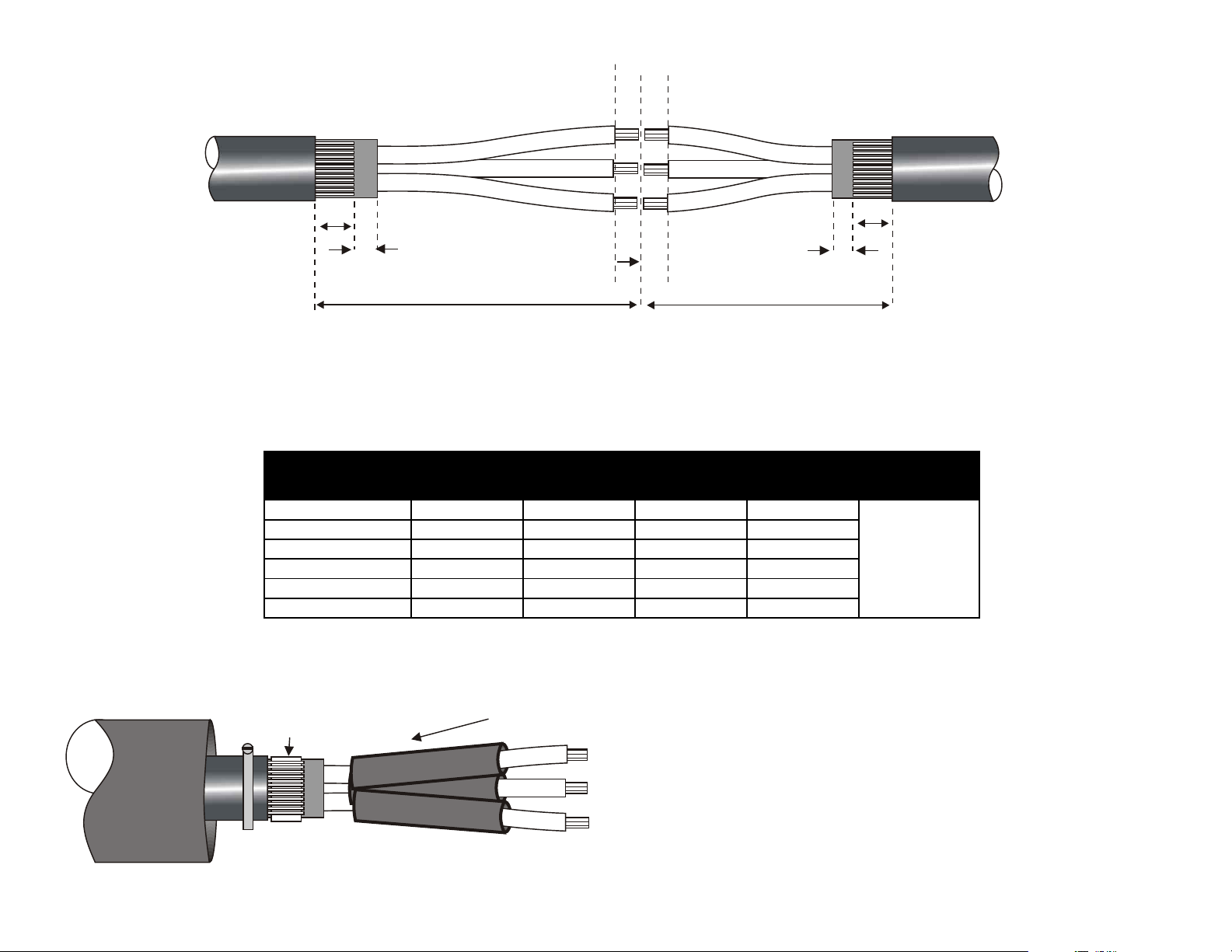
X
1.5-6 150 90 10 30
10-16 170 135 15 35 HALF
25-50 215 135 20 45 CONNECTOR
70-95 300 200 20 50 LENGTH
120-185 400 300 20 60
240-400 530 390 30 75
SHOWN FOR CLARITY
X
Fig 1
A
B
LONG SIDE
STRIP TO ½ LENGTH OF
CONNECTOR
X
SHORT SIDE
A
B
1. Ensure that the Cables overlap and prepare as above using the dimensions given in Table 1 below.
2. Slide the Outer Shrink Tubes, Armour Clamps and Copper Sock (If used) over the Cable end/s.
TABLE 1
CONNECTOR
ARMOUR
SUPPORT RING
INSULATION TUBES
OUTER
SHRINK
TUBE
Fig 2
LONG SIDE
3. Fit the Armour Support Rings (No need if Cable is
Steel Tape Armoured) before positioning the
Connector Insulation Tubes down the longer of the
Cores.
Page 3

OUTER
SHRINK
TUBE
Fig 3
4. Expose the Conductors to half the length of the Connectors and fit using a suitable tool to crimp them. Note:-
Mechanical Shearbolt Connectors can be used, but user should advise as Insulation Tubes will need to be increased in
size.
5. Position the Tubes centrally over the Connectors and shrink from the centre to one end at a time. Keep the flame on
the move to ensure an even wall thickness. Sealants will be visible at Tube ends once fully shrunk.
Note:- Heavy Duty Copper
Sock is supplied as opposed to
Cages for small Multicore and
Power Joints up to 50mm
2
OUTER
SHRINK
TUBE
Fig 4
6. Wrap the Armour Cage around the joint gap and secure to the Armours at both sides with the Armour Clamps provided
(Roll Springs if Copper Sock). Note:- User may need to apply Tape to the Cores to keep the joint profile down, particularly
in the case of core crossing.
Page 4

OUTER
SHRINK
TUBE
Fig 6
7. Tape over any sharp points including Clamp Buckles.
Figure 5 shows Copper
Sock secured to Armours
With Roll Springs
Fig 5
OUTER SHRINK TUBE
Fig 7
8. De-grease the Cable Sheaths with the Tissues provided.
Centralise the Tube and shrink from the centre to one end at
a time. Keep the flame on the move all around the Tube to ensure an even wall thickness.
9. Allow the completed Joint to cool before applying any mechanical strain.
IMPORTANT NOTICE TO PURCHASER:- Sellers and Manufacturere’s only obligation shall be to replace such quantity of the product proved to be defective. Neither the Seller nor
Manufacturer shall be liable for any injury, loss or damage, direct or consequential, arising out of the use or inability to use the product. Before using, User shall determine the
suitability of the product for his or her intended use and User assumes all risk and liability whatsoever in connection therewith.
UNITS P1-P3 GROVEMERE COURT BICTON INDUSTRIAL PARK KIMBOLTON CAMBS PE28 OEY
TEL: +44 (0) 1480 861001 FAX: +44 (0) 1480 861002 EMAIL: info@shrinkpolymersystems.co.uk WEBSITE: www.shrinkpolymersystems.co.uk
©
 Loading...