


Operating, Field Maintenance, and Parts Manual Model 998 UL®

Thank you for choosing Shrinkfast products. Please visit us on the web at
www.shrinkfast998.com for our latest product information and updates.
Customer Service Issues:
Before returning any Shrinkfast product, please call:
(800)867-4746 or
(603)863-7719
SAVE THIS MANUAL FOR FUTURE REFERENCE

TABLE OF CONTENTS
GENERAL SAFETY PRECAUTIONS............................................................................. pages 2-4
REGULATOR OPERATION & MAINTANANCE........................................................... pages 5-7
STARTING THE HEAT TOOL .............................................................................................. page 8
REGULATOR MAINTANANCE & SAFETY FEATURES ........................................... pages 9-10
EXCESS FLOW DEVICE ...................................................................................................... page 9
CHOOSING THE CORRECT PROPANE TANK ......................................................... pages 11-12
TANK PRESSURE, TEMPERATURE & OPERATION............................................... pages 13-14
VENTILATION REQUIREMENTS .................................................................................... page 15
GENERAL INFORMATION ON SHRINK FILM & SHRINK BAGS........................ pages 16-18
SHRINK WRAPPING TECHNIQUES
OPERATING OVERVIEW............................................................................................ pages 23-24
PRINCIPLES OF OPERATION .................................................................................... pages 25-27
HEAT TOOL PARTS DIAGRAM.................................................................................. pages 28-30
ASSEMBLY AND DISASSEMBLY ............................................................................. pages 31-35
HEAT TOOL SERVICE INSTRUCTIONS .......................................................................... page 36
DAILY HEAT TOOL INSPECTION .................................................................................... page 37
MONTHLY HEAT TOOL INSPECTION ............................................................................ page 38
TROUBLESHOOTING GUIDE .................................................................................... pages 39-40
TECHNICAL SPECIFICATIONS........................................................................................ page 41
(PALLET BAGS & ODD SHAPED OBJECTS)
..... pages19-22

GGEENNEE RRAALL SSAAFFEETTYY PPRREE CCAAUUTT IIOO NNSS --
RREEAA DD AA LL LL IINN SS TT RR UU CC TT IIOO NN SS
BB EE FF OO RR EE OOPPEERR AA TT IINN GG TTHH IISS HH EE AA TT TTOO OO LL
• Do not operate this heat tool below 15 PSI or damage to the heat tool will
occur.
• Before using any heat tool, check all parts for proper function and damage to
component parts including the hose, regulator and heat tool.
• "Hidden areas such as behind walls, ceilings, floors, soffit boards and other
panels may contain flammable materials that could be ignited by the heat tool
when working in these locations. The ignition of these materials may not be
readily apparent and could result in property damage and injury to persons.
When working in these locations, keep the heat tool moving in a back and forth
motion. Lingering or pausing in one spot could ignite the panel or the material
behind it."
• Do not use the heat tool to remove paint.
• Do not point this heat tool at anyone and do not operate in an area where there
is a risk of an explosion or fire.
2

GENERAL SAFETY PRECAUTIONS
•
When working with any type of heat or open flame, always keep a fire
extinguisher close by.
•
Always were safety glasses and gloves (flame retardant or leather is suggested)
when shrink wrapping. Never obstruct or cover the air inlet at the back of the
heat tool. If the air flow is reduced the heat tool will not work properly.
•
When shrink wrapping outdoors, do not shrink wrap when the wind is stronger
the 10 mph.
•
When shrink wrapping indoors, make sure the work area is well ventilated.
•
Keep the work area clear of debris, wood shavings, paper products, flammable
chemicals and anything else that may catch fire from the heat of the tool.
•
Do not wear loose clothing while shrink wrapping and also keep long hair tied
back.
•
Stay alert, watch what you are doing, and use common sense when operating
the heat tool. Do not use tool while tired or under the influence of drugs,
alcohol or medication. A moment of inattention while operating the heat tool
may result in serious personal injury.
•
Do not overreach. Keep proper footing and balance at all times. Proper footing
and balance enables better control of the heat tool in unexpected situations.
3

•
Never operate the heat tool with the combustor nozzle hard up against a surface;
this could ignite any material you are shrink wrapping.
•
Do not place the combustor nozzle (where the flame comes out of the heat tool)
next to anything while it is hot. Never allow the combustor nozzle to come in
contact with clothing or skin.
•
Do not look down the combustor nozzle while the tool is in operation or
attached to a fuel source.
•
The heat tool should be kept 6” – 8” away from the shrink film when in
operation. Never keep the heat on one area for more than a few seconds.
Once heat is applied to the shrink film, it will continue to shrink even after
the heat is moved away from the area.
•
Never modify the tool in any way and use only Shrinkfast replacement parts
.
•
Never operate in a basement or closed in, non-ventilated area.
•
Never operate the heat tool on an area that you cannot see.
•
Always operate the heat tool with the UL® Guard installed.
4
REGULATOR OPERATION & MAINTANENCE
Regulator Technical Overview:
•
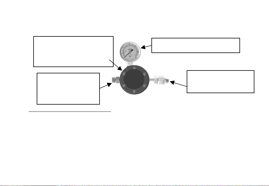
The MEGR-6120 is a high capacity, pounds to pounds, industrial gas regulator.
It is designed to conform to UL® Standard 144 for use with LP Gas. The
maximum supply pressure is 250 PSIG. The maximum output pressure is
printed on the regulator nameplate.
•
This regulator is not intended for use in pressure applications below 3 PSIG and
the heat tool should not be operated at a pressure below 15 PSIG. The
operating temperature range is -40 to +200 degrees Fahrenheit.
0 – 30 PSI Pressure Gauge
POL – Attaches to
the Propane Tank
Hose Adapter –
Attaches to the
Supplied 25’ Hose
Adjustable Hand Wheel
– Adjusts PSI Setting of
the Regulator
5
This is a variable regulator assembly and the heat tool will operate
properly between 15 PSI and 30 PSI. The pressure can be changed by
loosening the hex nut located under the black, round hand wheel on the
regulator assembly and then turning the hand wheel to the desired pressure.
However, the optimum and factory recommendation is that you do not
adjust the pressure and keep the regulator set at the factory setting of 22
PSI.
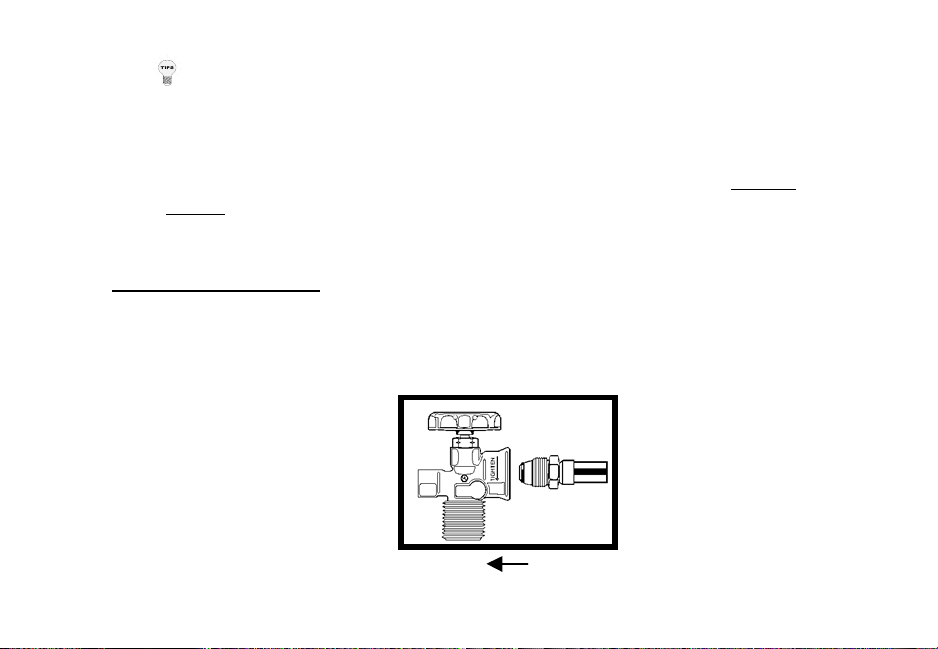
Regulator Installation:
1. Remove the yellow cap from the POL (brass, bull nose fitting) and connect the
POL to your propane tank and tighten with the supplied wrench (all threads
are left handed thread, so tighten counter clockwise).
Propane Tank Regulator POL
6
2. Connect one end of the supplied 25’ hose to the hose adapter on the regulator
and the other end of the hose to the heat tool. Tighten all fittings with the
supplied wrench (left handed threads, so tighten counter clockwise).
3. Open the propane tank valve and check for any leaks by spraying a soapy
water mixture on the fittings. If any bubbles are visible, shut off the propane
tank and tighten the fittings.
4. When you first turn on the propane tank, the pressure gauge on the regulator
will slowly move toward the factory setting of 22 PSIG. Once the hose is fully
pressurized, the needle on the gauge will stop at 22 PSIG. Now the heat tool is
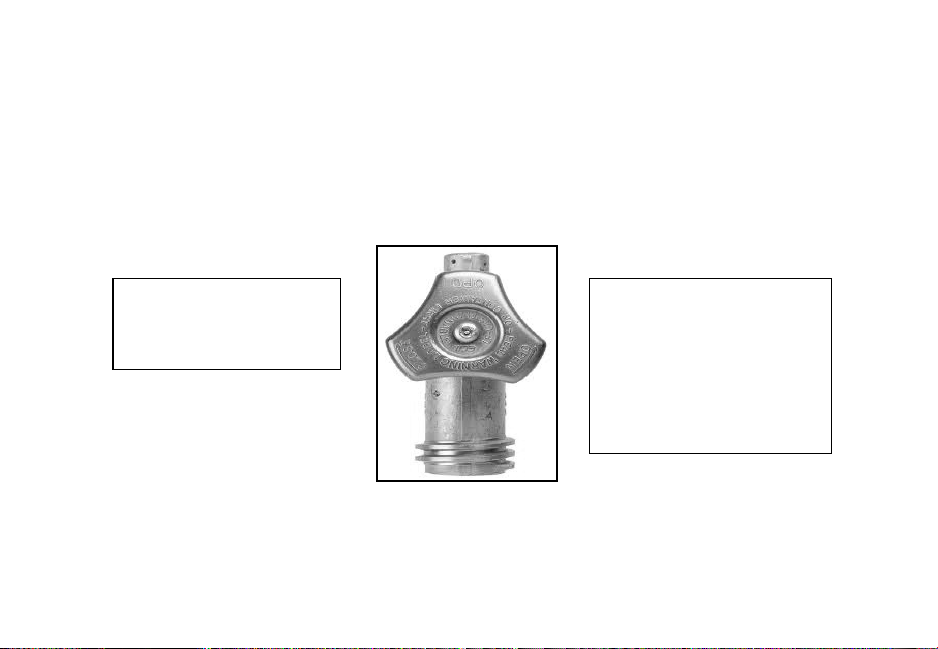
ready to be fired.
To open the flow of
propane, turn the tank
hand wheel in a counter
clockwise motion and
watch the regulator gauge
increase to the required
22 PSI.
Pictured: Hand wheel
on top of your supplied
propane tank.
7

STARTING THE HEAT TOOL
1. Depress the yellow safety that sits in the palm of your hand. If you do not
depress the safety first, you will not be able to pull the trigger with your finger
tips and ignite the heat tool.
2. With the safety depressed, slowly pull the trigger with your fingertips so you
first hear a slight “hissing” of propane flow, then pull the trigger completely
and the heat tool will “click” then ignite.
3. Should the gun fail to ignite, release both the safety and trigger fully to ensure
that the igniter is reset and repeat the starting procedure.
WARNING: MANY NEW USERS PULL THE TRIGGER TOO
QUICKLY AND MULTIPLE TIMES BELIEVING THIS IS THE BEST
WAY TO IGNITE THE HEAT TOOL. PULLING THE TRIGGER TOO
QUICKLY DOES NOT ALLOW THE PIEZO CRYSTAL INSIDE THE
IGNITER TO SEND PROPER VOLTAGE TO THE SPARK PLUG, SO
PULL THE TRIGGER SLOWLY IN ORDER TO IGNITE EVERY TIME.
WARNING: DO NOT TOUCH THE WIRE METAL SHIELD (UL®
GUARD) AFTER THE HEAT TOOL HAS BEEN FIRED.
!
8

REGULATOR MAINTENANCE & SAFETY FEATURES
• Because the Shrinkfast UL® approved regulator assembly is assembled and tested at the
factory to conform to UL® Standard 144, any maintenance or repairs should be in
accordance with this listing as well as any other applicable regulations. Regulator parts
showing wear should be replaced as necessary. Contact your local distributor or
Shrinkfast directly for descriptions and part numbers.
IMPORTANT SAFETY FEATURE: Inside the POL fitting on the
Regulator Assembly there is a safety featured called the “Excess Flow Device”.
• This safety feature is designed to stop the flow of propane if the hose becomes
cut or detached from the regulator or heat tool during operation.
• The Excess Flow Device does not stop the propane flow 100%, but it does
reduce the flow so the user has time to get to the tank and shut off the propane
and prevent a dangerous situation from occurring.
How the Excess Flow Device Works:
• When the propane tank is first turned on the Excess Flow Device believes there
may be a downstream leak and temporarily closes the POL. The POL does not
stop the flow entirely, so there is enough propane entering the hose to begin
pressurizing the system.
9

• Once the fuel has filled the entire hose and the regulator gauge reaches 22 PSI,
the Excess Flow Device reopens and the heat tool is ready for operation (you
will hear an audible “click” from the POL when the pressurization is
complete).
• This pressurization process can take anywhere from 7-10 seconds from when
the tank is first turned on and may take a little longer with propane tanks that
are partially filled. This feature is all for the safety of the user, but you must
wait the 7-10 seconds for the pressurization to complete before operation.
Attempting to Ignite the Heat Tool before Pressurization is Complete:
• If the user attempts to fire the heat tool before the pressurization is complete,
the pressure gauge will drop down to 0 PSI and the heat tool will not ignite. In
order to ignite the heat tool, the user must wait for the system to pressurize (22
PSI) and then the heat tool will operate properly. *This wait time will only
occur when the user first turns on the propane tank.*
WARNING: As the amount of propane in the tank drops, the pressure
gauge on the regulator will decrease accordingly. Do not operate the heat
tool once the pressure drops down to 15 PSIG. Operating the heat tool
below 15 PSIG, will result in damage to the heat tool’s internal components.
10
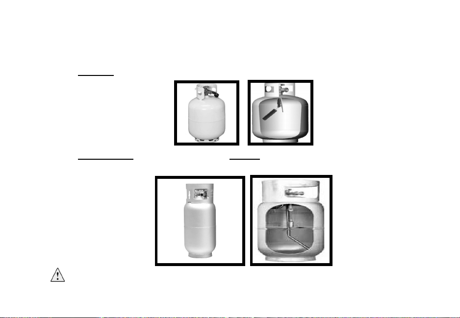
CHOOSING THE CORRECT PROPANE TANK
• !"#$#%&$#%'()%'*+#,%)-%+$)+&.#%'&./,%0)11).2*%&3&42&52#6%
A.
Correct: Vapor withdrawal—Use this style (exactly the same as a BBQ grill tank)
B.
Not Correct: Liquid withdrawal—Do not use this style (used on fork trucks)
%% %
WARNING: Using a liquid withdrawal (fork truck) propane tank will clog
the orifice in the heat tool and result in an extremely long and dangerous flame.
11
%
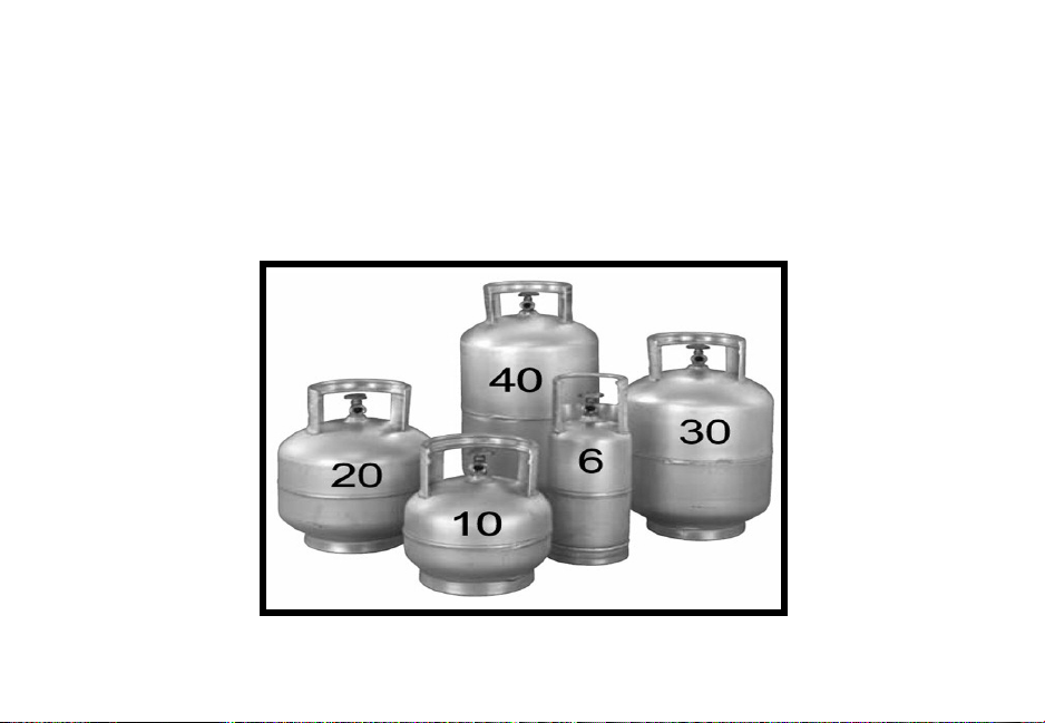
CHOOSING THE CORRECT PROPANE TANK (CONTINUED)
• Propane tanks are available in a variety of sizes. The most popular tank sizes:
• 20 lb. tank similar to a BBQ propane tank for smaller
applications.
• 40 lb. tanks are commonly used in most industrial applications.
12

TANK PRESSURE, TEMPERATURE & OPERATION
• Tank pressure depends on the temperature of the tank. At room temperature (72°F) the
pressure in a full tank is 110 PSI and drops to 22 PSI at 0°F.
If the propane tank ices up during operation:
When the heat tool is in operation, the temperature of the tank drops due to the
evaporation process of liquid propane to propane gas. After prolonged use and
continued drop in propane pressure, the temperature of the tank may drop to 0°F
usually accompanied by icing on the outside of the tank and regulator.
13

WARNING: Icing of the tank and regulator is quite common when
running the heat tool continuously with a partially filled propane tank.
However, if you are ever in doubt regarding the safety or operation of
your heat tool, shut off the tank and contact your authorized Shrinkfast
distributor or Shrinkfast directly.
• Small or nearly empty tanks ice up faster than larger, full tanks. Typically, a
full 20 lb. tank, if operated continuously, will run for 90 minutes before ice
builds up on the outside of the tank.
• If your shrink wrapping project requires continuous use of the heat tool, try the
following methods:
• Use multiple tanks—Switch the heat tool from one tank to
another.
• Use a portable fan—Point an ordinary desk fan at the tank, and
the air flow around the tank will help the tank from icing up.
14

VENTALATION REQUIREMENTS
WHEN OPERATING HEAT TOOL
WARNING: During operation, the heat tool consumes propane and air
and produces carbon dioxide, carbon monoxide (CO), and water vapor.
Prolonged exposure to Carbon Monoxide is lethal and adequate
ventilation must be provided if the heat tool is to be operated indoors.
•
To maintain a safe CO concentration (50 parts per million as set by OSHA
Standard 1910.1000 – Air Contaminants), ventilation requirements are 2,000
cu. ft. /min. of fresh air while the heat tool is operated at a maximum operating
pressure of 30 PSI.
•
Based on a 1 1/2 minute heating cycle per pallet, the fresh air requirements are
3000 cu. ft. /pallet. Example: If the production rate is 10 pallets per hour, a
ventilation system needs to provide 500 cu. ft. /minute.
•
In areas where ventilation is provided by open doors or windows, a safe level of
CO will be maintained as long as the room temperature does not rise above
150°F.
15

GENERAL INFORMATION ON SHRINK FILM & SHRINK BAGS
Shrink Wrap (#4 LDPE):
• The shrink wrap is manufactured in multiple colors and is typically a 6 or 7 mil,
low density polyethylene (#4 for recycling purposes). What makes this material
different than construction plastic sheeting is that it contains shrinking resins,
UV inhibitors, anti-brittling compounds, and strengtheners so that it will not rip
or tear. Make sure the shrink film is manufactured using only virgin resin
material.
WARNING: Shrink wrap can burn. If heat is applied incorrectly, shrink
wrap can ignite into open flame. It can also drop down on to other
combustible material and cause secondary ignition and fire. If at any time
you observe the shrink wrap on fire, immediately stop what you are doing
and carefully inspect the area where you are working for a possible fire.
Keep a fire extinguisher available at all times.
Measuring for the Shrink Film:
• Regardless of the shape of the object you are covering, it must be viewed as a
cube in order to find the proper shrink film size. In general, you measure the
width by starting at the lowest point of the object or however far down you
16

want the film cover to reach. Measure up the side, over the top, and down the
opposite side to the lowest point. Add one foot to this number to accommodate
heat welds and this will indicate how wide your shrink wrap should be. This
process will determine the square footage of the object being shrink wrapped.
• For boat wrapping or storage purposes, a 6 or 7 mil shrink film is installed, but
the mil thickness depends on the project requirements and can be best
determined by a shrink film distributor.
Measuring for the Shrink Pallet Bags:
• For shrink wrapping a pallet, a 4 mil shrink bag is typically used for loads of
1,000 lbs. or less. You should always add at least 2" to the length and width of
your measured object when sizing the correct pallet bag and at least 4-6" to the
height (including the pallet) to account for the material shrinking when
applying the heat.
• Again, not all plastic bags are shrink bags; therefore, be specific. Shrink film
should be made of virgin resin, and not reprocessed material.
17

MEASURING FOR A SHRINK PALLET BAG
1) Measure the length, width and height of the
pallet to be covered.
2) Determine the Length (L) of the bag, by
adding 2" to the length of the pallet.
3) Determine the Width (W) of the bag, by
adding 2" to the width of the pallet.
4) The Height (H) of the bag is determined by
measuring the height of the pallet (including the
height of the pallet itself) and adding 4-6”. The
added length allows you to tuck the ends of the
bag under the pallet before applying heat so
that it does not pull up over the pallet edges.
Example: If the pallet size is 48"(length) x
40"(wide) x 50"(height), the bag dimensions are
as follows: Length (L) is 50", Width (W) is 42"
Height (H) is 56" (always go higher in height if
they do not have the exact bag height available).
18

19

SHRINK WRAPPING TIPS
• During operation, always have the heat tool moving in a side to side motion.
The most important fact to keep in mind is that heat only softens the film. The
greatest amount of shrinking occurs as the film cools.
• It is a common mistake to apply too much heat to one particular area of the
shrink film, thus burning a hole in the film. Keeping the heat tool continuously
moving will prevent this from occurring.
• With a little practice, you will find that you can hold the heat tool closer to the
film and sweep faster often shrinking a pallet in less than 4 minutes.
• It is absolutely necessary that the four corners of the bag be taut under the pallet.
If this is not done, the effectiveness of shrink palletizing is considerably
reduced.
20

PATCHING HOLES IN SHRINK WRAP FILM!
• MISTAKES HAPPEN! Occasionally holes will appear in the shrink film, but
they can be easily repaired. Holes in the film can be patched by laying a square
piece of shrink film over the hole and applying heat around the edges, thus heat
welding the patch to the bag. Note: Make sure you cut the film patch at least 2”
larger on all sides before applying heat to the patch.
After applying heat to the patch of film, tap the warm film with the back of your
glove to ensure the film is secured over the hole. The same technique can be
applied to reinforce edges or corners. After the patch has cooled, apply shrink
tape to all four sides to further secure the patch.
WARNING: After shrink wrapping, never touch the shrink film with
your bare hands.
!
21

SHRINK WRAPPING LARGE OR ODD SHAPED LOADS!
• Shrink wrapping is a versatile process that can be employed in a variety of
applications. For example, shrink wrappers routinely wrap irregular objects
such as industrial equipment.
Objects, which are too big to fit under a bag, can be wrapped by using several
sheets of shrink film joined together if the following the precautions are observed:
• When adjoining sheets of film there should be an 18 inch overlap. This
overlap allows the sheets to weld together during the shrink process.
• The sheets of film must be secured around the entire base of the pallet and
attached to the skid with strips of wood strapping or any other method that
can secure the film and prevent it from pulling up on the object when heat
is applied.
• Once the film is firmly attached to the pallet, the heat tool is used to shrink
the film, again using a back and forth motion, starting at the bottom of
the object and working your way to the top.
22

OPERATING OVERVIEW
O
PERATING O
23

PART AND FUNCTION
1 Safety: Prevents accidental gas release
2. Trigger: Activates gas valve and igniter
3. Valve: Opens fuel flow
4. Igniter: Fires the piezoelectric spark igniter
5. Fuel Line: Carries fuel to orifice
7. Orifice: Controls fuel flow through pump body
8. Spark Plug: Ignites fuel
9. Flame Holder: Prevents flashback and flame out
10. Hose: Connects regulator and heat tool
11. Adjustment Knob: Adjusts pressure on regulator
12. Regulator: Regulates fuel pressure to heat tool
13. Pressure Gauge: Indicates pressure in the line
14. POL Fitting: Connects regulator to tank and contains excess flow valve
15. Propane Tank: See “Choosing the Correct Propane Tank” section
24
16. Tank Valve: Opens/closes fuel supply

25

PRINCIPLES OF OPERATION
The Model 998 offers an improved jet pump using a multi nozzle orifice. The jet
pump is shorter and more efficient with the benefits of a wider and more powerful
heat pattern. The 998 is basically a simple jet engine, the high energy exhaust of
which is used to pump and heat the surrounding air and deliver an air blast of high
velocity and moderate temperature. Its’ effectiveness is based on the high level of
technical development which has gone into optimizing each stage of operation:
1. Jet Pump. The propane jet (A) draws the correct amount of combustion air
through the air inlet (B). They mix together in the straight section (C).
2. Compression. The conical section (D) turns speed into pressure.
3. Combustion. The combustion process is carried out inside the combustor (E).
The flame holder (F) prevents flashback (where the flame travels back into the jet
pump) and the flame out (where the flame is blown out of the combustor).
Another proprietary function of the flame holder is to achieve the effect of
maintaining cold combustor walls in spite of the fact that the combustion is
substantially completed inside the combustor. This is done by imparting a swirl to
the mixture. During combustion, the burned portion of the mixture expands, and
26

its’ density diminishes. The swirl centrifuges the unburned, heavier portion
outward and thereby creating a blanket of cold mixture along the walls. As
combustion proceeds, the process draws from the protective layer of unburned
mixture, and when combustion is completed the cooling effect stops. The size of
the combustor ensures that for rated flow the point of completion coincides with
the outlet. Operating at less than rated pressure, the blanket of unburned mixture
does not extend all the way to the outlet and results in a red hot combustor outlet.
4. Expansion. By virtue of the internal combustion process at elevated pressure a
portion of the heat energy is converted to exhaust gas velocity. The gasses are
expanded into the atmosphere through the combustor (E) with a velocity of over
160 MPH and a noticeable amount of thrust.
5. Entrainment. A second jet pump effect is created by the exhaust gases as they
leave the combustor. The slot shaped outlet of the combustor creates a large
mixture interface and promotes high volume entrainment within an unusually
short distance. The exhaust gases transfer their heat and momentum to the
entrained air and thus create a stream of high volume, low temperature air.
27

28

29

MODEL 998 PART NUMBER AND DESCRIPTION
Part #
Description
Part #
Description
1
Filter Holder
25
Contact Screw
2
O ring
26
Contact Spring
3
Filter Screen
27
Socket
4
Filter Spring
28
Spark Plug
5
Orifice Assembly
29
Assembly Screws (10)
6 & 24
O ring
30
Combustor
7
Retainer
31
Button
8
Inlet
32
Flame holder
9
Fuel Line
33
O ring
10
Pump Body
34
Strap
11
Label, Right Hand
35
Button Spring
12
Label, Left Hand
36A
Hose Assembly
14
Name Plate
37
Regulator
15
Housing, Right Hand
38
POL
16
Housing, Left Hand
39
Gauge
17 & 18
Trigger/Igniter Assy
40
Carrying Case
20
Safety
41
Guard Screw
21
Spring
43A
UL® Guard
22
Valve Assembly
44A
Wrench
23A
Hose Adapter
30

ASSEMBLY AND DISASSEMBLY
1. Filter Cleaning
1.1 Unscrew filter holder (1) using a screw driver or a coin. Pull out the filter holder.
1.2 Pull out the filter screen/spring assembly (3, 4) and clean with compressed air or
replace.
2. Spark Plug Replacement
2.1 Depress button (31) and remove combustor assembly (30).
2.2 Pull spark plug (28) and flame holder (32) out with a pair of pliers.
ASSEMBLY AN
nianel Crtel
i
retlfwercnsU
vidrwerc
ng
iusrdehol
tlfhet
outlulPn.oicorr
rdeholre
t
tlfhet
outlulP2 ec
lpre
l Pk
p
2. S
on tbut
epreD2.
n
iprn/eercrey blme
g
t
l
ortbusomc
ovemernd
epromch tiwn elcnd
4)
(
y
blme
orrid e
ug
pl
k
rpalulP2 2.
rdeholemfnd
28)
reiplofripah tiwout
31

2.3 Unscrew spark plug. Note: spark plug the cable (17, 18) and the contact spring gap
should be set to 3-5mm. (26).
3. Trigger/Igniter Replacement
3.1 Undo the 5 mounting screws (29) and remove right housing (15).
3.2 Undo contact screw (25) which retains the trigger/igniter cable (17, 18) and the
contact spring (26).
3.3 Snap off the strap (34) with a screw driver.
k
rpawercnsU2.ottebdlu
o
ug
pl
ce thglu pk
rpte
o
26)
m
ctano ce thdn
a
)
(
le
b
p gg
in
rpt s
3. /te
I
oumhetndo Utcontcndo U2 )2gnirptnco
t mel
R
omernd
29)
wer
c
ng
i
unthetnsiterh chi
w
25)
wer
c
ng
i
hous
ght
irleb crite
n
/ig
r
e
g
ig
tr
)
(
n ahetd
hetofp na
r
p
reivr dwerc s a
ith
w)4
(
32

3.4 Pull out trigger/igniter cable (17, 18).
3.5 Trigger/igniter assembly (17, 18) can now be lifted out.
4. Orifice Replacement
WARNING: The orifice (5) consists of 6 slender, thin walled tubes which can easily
be bent or damaged if dropped or mishandled. Once bent, the performance of the gun can
be seriously impaired. For this reason the following operation should be performed with
utmost care.
outlulP4 re
g
ig
tr/r
e
g
g
irite
n
ig
r
ite
n
/ig
e lcab
).
y
lbemwonn
c
)
tuodefile
b
l Rfi
NINRWA Td gemdaorntbe
be
t
(
eifr oeho
c) oftinsd.endlhasimord
oppe
drfi
hwubetd ellwn hitr
ndeelencmf
rpehetntbee
nc
y
lien ch cn a
c
gun
hetof
r
ipam
iy l
ousirebeerctosm
ut
d.eollfehtnoerihtr
Fo
epebdluohnoitrepogniw
htiwdemrf
r
33

4.1 Remove the right housing (15) as shown in operation 3.1
4.2 Undo the 3 mounting screws holding the pump body (10) and remove the pump first
by sliding it away from the orifice and then lifting it out. This sequence is important
because the orifice reaches inside the pump. Lifting the pump before sliding it away will
damage the orifice tubes.
4.3 Unscrew the orifice (5).
4.4 Use a .6mm drill to clean out each orifice stem.
omeR4.girhetveomhet
ndo U2
4.
ng
i
hous
ninwo
h
)
pu
he
t
ng
di
holwerc
ng
i
unt
noitra
epo
p
y
do b (tevomred
n
)
trsfpm
upe
h
fy wti
ng
diil
by
ecfiorheteuscbeecfiorhe
tgemdaorhetwercnsU
4.
filn hetnd ecfiorhetomdeinsihecer
ipm
u pethubetecf
i
)
(
iiencehioutti
ng
iinlid serfe bpm
u pe
th
g
nt
t
por
m
ill
wyaw it a
g
idrmesU4
4.
ecfiorh ceoutn aelco tl
l
met
34

35

HEAT TOOL SERVICE INSTRUCTIONS
•
In the event that your heat tool requires servicing or repair work performed,
Shrinkfast and/or your distributor can provide a parts list and assembly diagram
as a reference tool only.
•
Neither Shrinkfast nor the distributor make any representation or warranty of
any kind to the buyer that he or she is qualified to replace any parts of this or
any other Shrinkfast product. Shrinkfast and/or your distributor expressly states
that all repairs and part replacements should be undertaken by certified and
licensed technicians and not by the buyer.
•
The buyer assumes all risks and liability arising out of his or her repair to the
original product or replacement parts thereto, or arising out of his or her
installation of replacement parts.
•
If you require any assistance with servicing or repair work, you can contact your
local distributor or Shrinkfast direct at 603.863.7719 or via email at
info@shrinkfast-998.com
•
Shrinkfast provides free estimates on any repair or service request.
36

DAILY HEAT TOOL INSPECTION
•
Before turning on the heat tool, visually inspect the hose for any cracks or
breaks that can cause a propane leak.
•
When you turn on the gas at the propane tank, make sure the regulator gauge
pressurizes to 22 PSI before firing the heat tool and then leak check all fittings
and connections.
•
If you suspect a leak, use a spray bottle of soapy water and spray directly on
each connection to detect any leaks – indicated by bubbles coming from the
connection.
•
Before firing the heat tool, make sure you do not have a strong smell of propane
or hear any “hissing” which would indicate a possible leak inside the heat tool.
•
When you are finished using the heat tool (at any time during the day), shut off
the propane tank and pull the trigger on the heat tool to purge any remaining
gas inside the hose.
WARNING: Do not operate the heat tool if the pressure on the gauge
drops below 15 PSI. Operating the heat tool below 15 PSI will cause the
flame to burn inside the heat tool and damage the internal components
voiding the warranty.
37

MONTHLY HEAT TOOL MAINTANENCE
•
Using compressed air, depress the yellow button and then pull off the combustor
(part # 30 in assembly diagram) and clean out any debris inside the combustor
assembly.
•
Using compressed air, clean out the main body of the heat tool (part # 10).
•
Using compressed air, remove the filter holder assembly with a flat blade
screwdriver (part # 1, 4, 3) in the back of the heat tool and clean the screen.
•
Inspect the o rings (part # 33) inside the combustor for cracks and replace if
necessary or apply o ring lubricant.
38

TROUBLESHOOTING GUIDE
Problem
Probable Cause
Remedy
Gun will not ignite
Safety and/or trigger are not fully
depressed.
Depress the safety first, and then pull the
trigger to ignite.
Trigger is pulled to quickly
Squeeze the trigger slowly to ensure the
propane has entered the combustor before
firing.
Propane tank pressure too low
Check the regulator to make sure the Gauge is
reading a minimum of 15 PSI.
Propane tank valve is not turned
on.
Turn on tank valve and check the regulator
gauge for proper pressure setting.
Defective igniter
With propane turned off and gas purged from
the hose, check for spark in the combustor.
39

Problem
Probable Cause
Remedy
Gun will not
The POL excess check valve
has not fully opened.
Turn on propane tank valve and wait 10
seconds or until the needle on the regulator
has reached the factory setting of 22 PSI.
An audible “click” will be heard when the
hose has fully pressurized with gas.
Clogged orifice
Remove and clean with compressed air.
Clogged fuel line
Remove and clean with compressed air.
Clogged pump body
Remove and clean with compressed air.
Clogged hose assembly
Disconnect and clean with compressed air.
Combustor turns
glowing red
Low pressure from tank
Increase pressure from tank or replace tank.
Extremely large
flame
Wrong fuel type
Do not use a fork truck tank; only vapor
withdrawal tanks like a BBQ tank.
Tank, regulator or
hose fittings have
iced up.
Low pressure from tank
Increase pressure on regulator or change to
a new tank.
40

TECHNICAL SPECIFICATIONS
OUTPUT CHARACTERISTICS
MODEL 998 TECHNICAL SPECIFICATIONS
OPERATING PRESSURE of 22 PSIG
Distance / Ft.
Temperature / F
Velocity / Ft./Min.
6”
1120
2100
1’
650
1200
2’
390
660
Heat Capacity
172,500 BTU / Hr.
Propane Consumption
8.0 Lbs. / Hr.
Operating Pressure
22 PSIG
Weight
2 Lbs. 2 Oz.
Air Consumption
30 CFM
Emission
.015 CO/CO2
41

SHRINKFAST
460 Sunapee Street
Newport, NH 03773-1488
(800)867-4746 or (603)863-7719
 Loading...