

Page 1
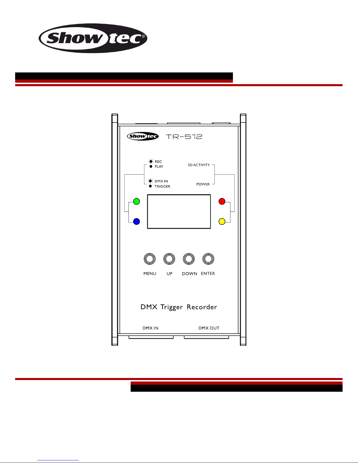
TR-512 V2
Highlite International B.V. – Vestastraat 2 – 6468 EX – Kerkrade – the Netherlands
Ordercode: 50825
MANUAL
ENGLISH
Page 2

1
Ordercode: 50825
TR-512
Table of contents
Warning ............................................................................................................................................................................... 2
Safety Instructions ......................................................................................................................................................... 2
Operating Determinations .......................................................................................................................................... 3
Connection with the mains......................................................................................................................................... 4
Return Procedure .......................................................................................................................................................... 4
Claims .............................................................................................................................................................................. 4
Description of the device ................................................................................................................................................. 5
Overview ........................................................................................................................................................................ 5
Installation ........................................................................................................................................................................... 6
Set Up and Operation ....................................................................................................................................................... 6
Control Modes ............................................................................................................................................................... 6
Data Cabling ................................................................................................................................................................. 7
Control Panel ................................................................................................................................................................. 7
Control Mode ................................................................................................................................................................ 7
Main Menu Options ...................................................................................................................................................... 8
1. Play Show ................................................................................................................................................................ 8
2. Record Show .......................................................................................................................................................... 9
3. Delete Show .........................................................................................................................................................10
4. Trigger Event .........................................................................................................................................................11
4.1. Status ...................................................................................................................................................................11
4.2. Rename ..............................................................................................................................................................11
4.3. Show ....................................................................................................................................................................12
4.4. Mode ..................................................................................................................................................................12
4.5. Delay ...................................................................................................................................................................12
5. Stop TR Event ........................................................................................................................................................12
6. Device Settings ....................................................................................................................................................13
6.1. Device Label .....................................................................................................................................................13
6.2. DMX Port Option ...............................................................................................................................................13
6.3. Display Option ...................................................................................................................................................14
6.4. Version ................................................................................................................................................................14
7. Save Configuration .............................................................................................................................................15
8. Load Configuration .............................................................................................................................................16
9. Default Setting ......................................................................................................................................................16
RJ45 Connector ..........................................................................................................................................................17
Maintenance ....................................................................................................................................................................17
Troubleshooting ...............................................................................................................................................................18
No Light .........................................................................................................................................................................18
No Response to DMX..................................................................................................................................................18
Product Specifications ....................................................................................................................................................19
Dimensions ........................................................................................................................................................................20
Notes ..................................................................................................................................................................................21
Page 3
2
Ordercode: 50825
TR-512
Warning
Unpacking Instructions
Immediately upon receiving this product, carefully unpack the carton and check the contents to ensure
that all parts are present, and have been received in good condition. Notify the dealer immediately and
retain packing material for inspection if any parts appear damaged from shipping or the carton itself
shows signs of mishandling. Save the carton and all packing materials. In the event that a fixture must be
returned to the factory, it is important that the fixture be returned in the original factory box and packing.
Your shipment includes:
● Showtec TR-512
● MicroSD card
● 12V DC power adapter, 1500 mA (1,2 m)
● User manual
Safety Instructions
Every person involved with the installation, operation and maintenance of this device has to:
● be qualified
● follow the instructions of this manual
Before your initial start-up, please make sure that there is no damage caused by transportation.
Should there be any, consult your dealer and do not use the device.
To maintain perfect condition and to ensure a safe operation, it is absolutely necessary for the user to
follow the safety instructions and warning notes written in this manual.
Please consider that damages caused by manual modifications to the device are not subject to
warranty.
This device contains no user-serviceable parts. Refer servicing to qualified technicians only.
Page 4

3
Ordercode: 50825
TR-512
IMPORTANT:
The manufacturer will not accept liability for any resulting damages caused by the non-observance of
this manual or any unauthorized modification to the device.
● Never let the power cord come into contact with other cables! Handle the power cord and all
connections with the mains with particular caution!
● Never remove warning or informative labels from the unit.
● Never use anything to cover the ground contact.
● Never leave any cables lying around.
● Do not connect this device to a dimmer pack.
● Do not switch the device on and off in short intervals, as this would reduce the device’s life.
● Do not touch the device’s housing bare-handed during its operation. Allow the device to cool for at
least 5 minutes before handling.
● Do not shake the device. Avoid brute force when installing or operating the device.
● Only use device indoors, avoid contact with water or other liquids.
● Only operate the device after having checked that the housing is firmly closed and all screws are
tightly fastened.
● Only operate the device after having familiarized with its functions.
● Avoid flames and do not put close to flammable liquids or gases.
● Always keep case closed while operating.
● Always disconnect power from the mains, when device is not used or before cleaning! Only handle
the power cord by the plug. Never pull out the plug by tugging the power cord.
● Make sure that the device is not exposed to extreme heat, moisture or dust.
● Make sure that the available voltage is not higher than stated on the rear panel.
● Make sure that the power cord is never crimped or damaged. Check the device and the power
cord from time to time.
● If device is dropped or struck, disconnect mains power supply immediately. Have a qualified
engineer inspect for safety before operating.
● If the device has been exposed to drastic temperature fluctuation (e.g. after transportation), do not
switch it on immediately. The arising condensation water might damage your device. Leave the
device switched off until it has reached room temperature.
● If your Showtec device fails to work properly, discontinue use immediately. Pack the unit securely
(preferably in the original packing material), and return it to your Showtec dealer for service.
● For adult use only. Device must be installed out of the reach of children. Never leave the unit running
unattended.
● Never attempt to bypass the thermostatic switch or fuses.
● The user is responsible for correct positioning and operating of the TR-512. The manufacturer will not
accept liability for damages caused by the misuse or incorrect installation of this device.
● This device falls under protection class I. Therefore it is essential to connect the yellow/green
conductor to earth.
● Repairs, servicing and electric connection must be carried out by a qualified technician.
● WARRANTY: Till one year after date of purchase.
Operating Determinations
● This device is not designed for permanent operation. Consistent operation breaks will ensure that the
device will serve you for a long time without defects.
● The maximum ambient temperature ta = 40°C must never be exceeded.
● The relative humidity must not exceed 50 % with an ambient temperature of 40°C.
● If this device is operated in any other way, than the one described in this manual, the product may
suffer damages and the warranty becomes void.
● Any other operation may lead to dangers like short-circuit, burns, electric shock, crash etc.
You endanger your own safety and the safety of others!
Improper installation can cause serious damage to people and property !
Page 5
4
Ordercode: 50825
TR-512
Connection with the mains
Connect the device to the mains with the power-plug.
Always pay attention, that the right color cable is connected to the right place.
International
EU Cable
UK Cable
US Cable
Pin
L
BROWN
RED
YELLOW/COPPER
PHASE
N
BLUE
BLACK
SILVER
NULL
YELLOW/GREEN
GREEN
GREEN
EARTH
Make sure that the device is always connected properly to the earth!
Return Procedure
Returned merchandise must be sent prepaid and in the original packing, call tags will not be issued.
Package must be clearly labeled with a Return Authorization Number (RMA number). Products returned
without an RMA number will be refused. Highlite will not accept the returned goods or any responsibility.
Call Highlite 0031-455667723 or mail aftersales@highlite.nl and request an RMA prior to shipping the fixture.
Be prepared to provide the model number, serial number and a brief description of the cause for the
return. Be sure to properly pack fixture, any shipping damage resulting from inadequate packaging is the
customer’s responsibility. Highlite reserves the right to use its own discretion to repair or replace
product(s). As a suggestion, proper UPS packing or double-boxing is always a safe method to use.
Note: If you are given an RMA number, please include the following information on a piece of paper
inside the box:
01) Your name
02) Your address
03) Your phone number
04) A brief description of the symptoms
Claims
The client has the obligation to check the delivered goods immediately upon delivery for any shortcomings and/or visible defects, or perform this check after our announcement that the goods are at their
disposal. Damage incurred in shipping is the responsibility of the shipper; therefore the damage must be
reported to the carrier upon receipt of merchandise.
It is the customer's responsibility to notify and submit claims with the shipper in the event that a fixture is
damaged due to shipping. Transportation damage has to be reported to us within one day after receipt
of the delivery.
Any return shipment has to be made post-paid at all times. Return shipments must be accompanied with
a letter defining the reason for return shipment. Non-prepaid return shipments will be refused, unless
otherwise agreed in writing.
Complaints against us must be made known in writing or by fax within 10 working days after receipt of the
invoice. After this period complaints will not be handled anymore.
Complaints will only then be considered if the client has so far complied with all parts of the agreement,
regardless of the agreement of which the obligation is resulting.
Page 6
5
Ordercode: 50825
TR-512
Description of the device
Features
The TR-512 is a compact but very powerful tool which can be used for triggering any light show or scene
in a simple way. It can record and play several DMX shows at the same time. Those shows can be stored
on a microSD card. Shows can be played by 6 external triggers or by the internal auto trigger. Each
trigger can start either a show or a scene. Each show can be played in a loop mode or single play mode.
It is also possible to set a delay, which enhances your control of the shows. The TR-512 is suitable for a
large range of venues, such as: theme parks, museums, shops and many others.
● Input voltage: 100-240V AC, 50/60 Hz
● Power supply: 12V DC via the included power adapter, 1500mA
● Control protocol: DMX-512
● Connections: 3-pin XLR IN & OUT, microSD card IN, trigger connector RJ45 IN
● RJ45 connector for 6 external triggers
● Storage: MicroSD card (included)
● Housing: Aluminum extrusion
● IP rating: IP-20
● Dimensions: 115 x 67 x 45 mm (LxWxH)
● Weight: 0,4 kg
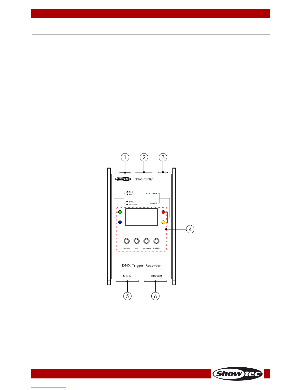
Overview
Fig. 01
01) MicroSD card IN
Insert the included microSD card and store your shows and configuration files.
02) Trigger connector RJ45 IN
Connect a maximum of 6 external triggers. Do not use for data transmission. See page 17.
03) 12V DC power adapter IN
04) LCD display + control buttons + LED indicators
05) 3-pin DMX signal connector IN
Connect a light controller (only when recording).
06) 3-pin DMX signal connector OUT
Connect a light fixture.
Page 7
6
Ordercode: 50825
TR-512
Installation
Remove all packing materials from the TR-512. Check that all foam and plastic padding is removed.
Connect all cables.
Do not supply power before the whole system is set up and connected properly.
Always disconnect from electric mains power supply before cleaning or servicing.
Damages caused by non-observance are not subject to warranty.
Set Up and Operation
Follow the directions below, as they pertain to your preferred operation mode.
Before plugging the unit in, always make sure that the power supply matches the product specification
voltage. Do not attempt to operate a 120V specification product on 230V power, or vice versa.
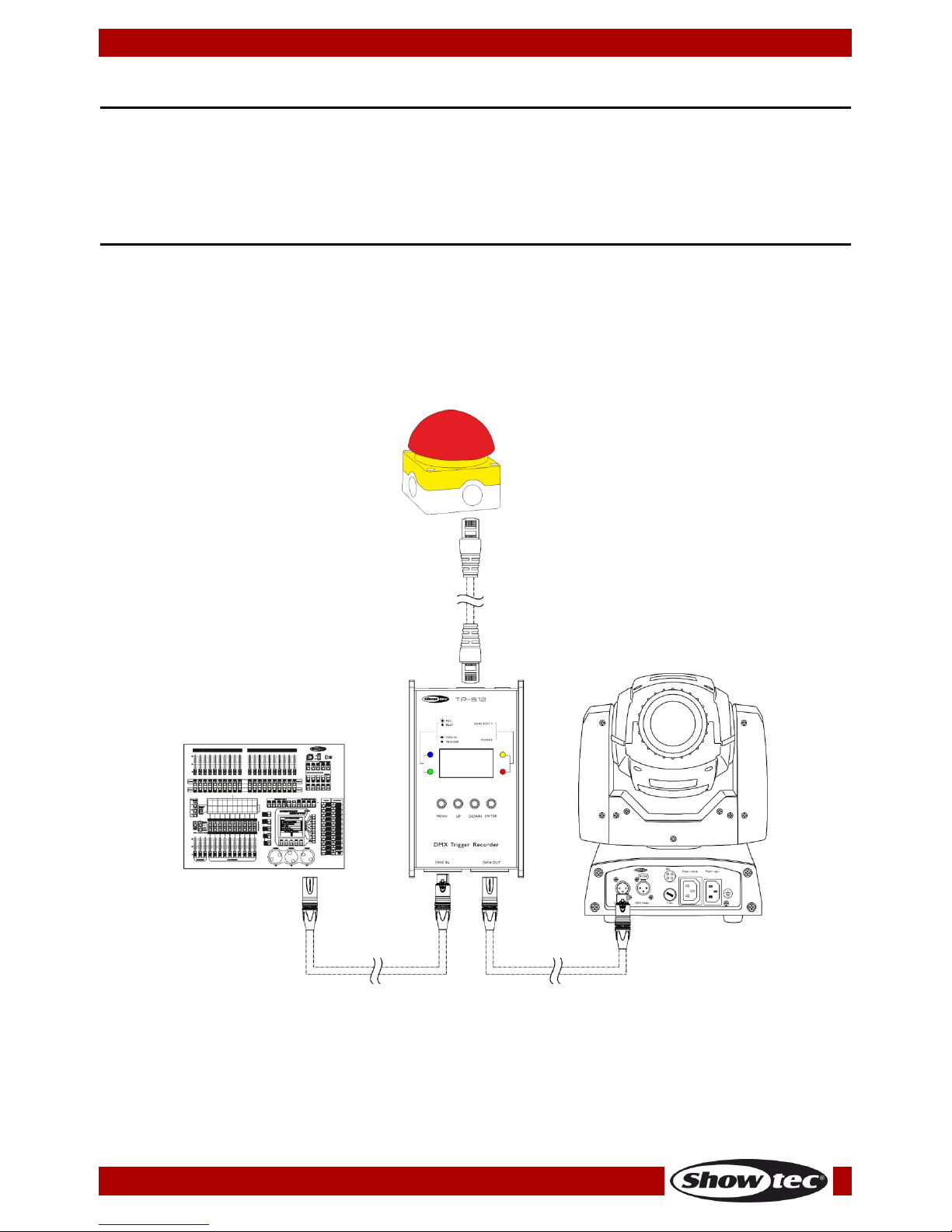
Control Modes
There are 3 modes:
● DMX player
● DMX recorder
● DMX trigger
Fig. 02
Note : Link all cables before connecting electric power
Page 8
7
Ordercode: 50825
TR-512
Data Cabling
To link fixtures together you must obtain data cables. You can purchase DAP Audio certified DMX cables
directly from a dealer/distributor or construct your own cable. If you choose to create your own cable
please use data-grade cables that can carry a high quality signal and are less prone to electromagnetic
interference.
DAP Audio DMX Data Cables
● DAP Audio Basic microphone cable for allround use. bal. XLR/M 3-pin > XLR/F 3-pin. Ordercode
FL01150 (1,5 m), FL013 (3 m), FL016 (6 m), FL0110 (10 m), FL0115 (15 m), FL0120 (20 m).
● DAP Audio X-type data cable XLR/M 3-pin > XLR/F 3-pin. Ordercode FLX0175 (0,75 m),
FLX01150 (1,5 m), FLX013 (3 m), FLX016 (6 m), FLX0110 (10 m).
● DAP Audio cable for the demanding user with exceptional audio-qualities and connector made by
Neutrik®. Ordercode FL71150 (1,5 m), FL713 (3 m), FL716 (6 m), FL7110 (10 m).
● DAP Audio cable for the demanding user with exceptional audio-qualities and connector made by
Neutrik®. Ordercode FL7275 (0,75 m), FL72150 (1,5 m), FL723 (3 m), FL726 (6 m), FL7210 (10 m).
● DAP Audio 110 Ohm cable with digital signal transmission. Ordercode FL0975 (0,75 m),
FL09150 (1,5 m), FL093 (3 m), FL096 (6 m), FL0910 (10 m), FL0915 (15 m), FL0920 (20 m).
● DAP Audio data cable FL08 DMX/AES-EBU, XLR/M 5-pin > XLR/F 5-pin. Ordercode FL08150 (1,5 m),
FL083 (3 m), FL086 (6 m), FL0810 (10 m), FL0820 (20 m).
● DAP Audio DMX adapter: 5-pin/3-pin. Ordercode FLA29.
● DAP Audio DMX adapter: 3-pin/5-pin. Ordercode FLA30.
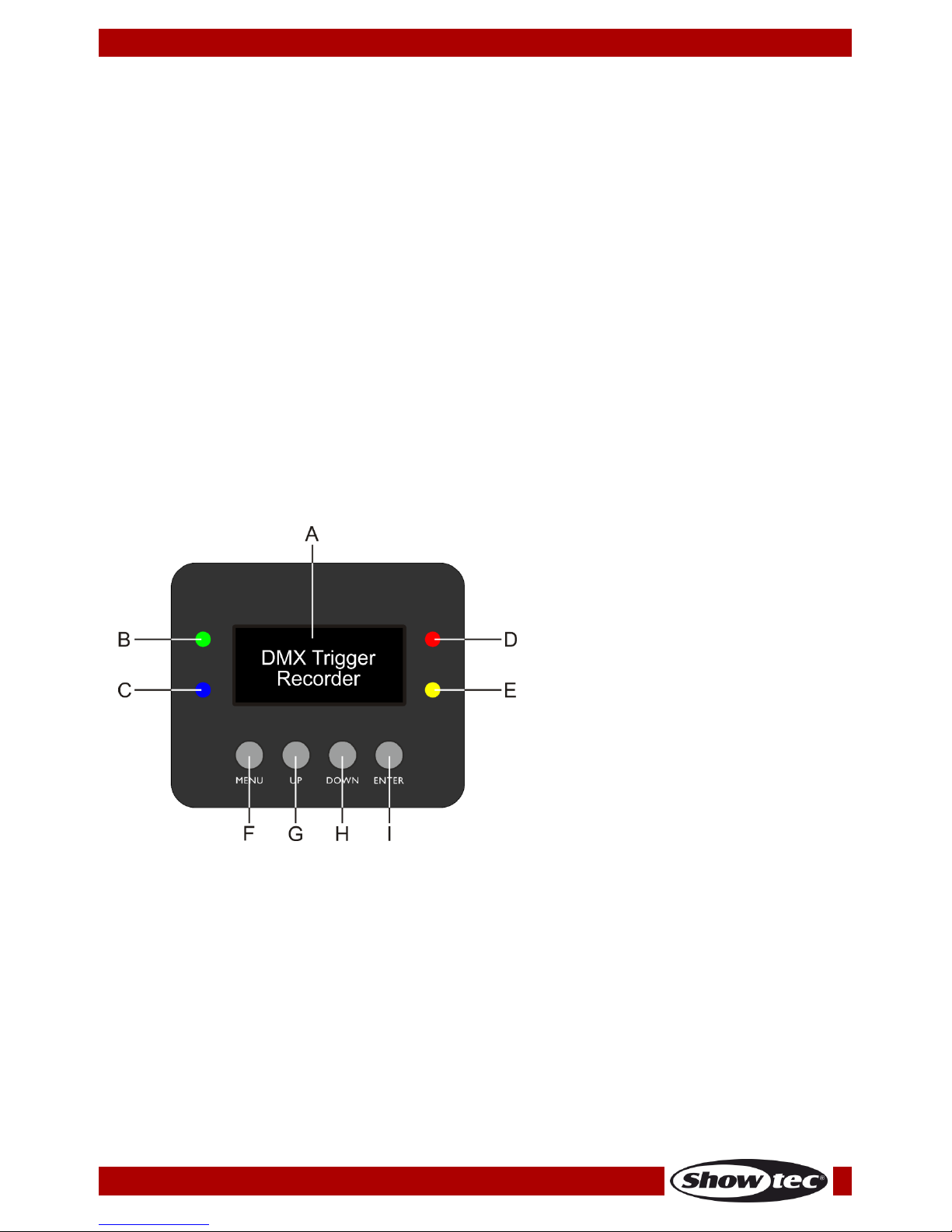
Control Panel
A) LCD display
B) Record/Play LED indicator
C) DMX IN/Trigger LED indicator
D) SD activity LED indicator
E) Power LED indicator
F) MENU button
G) UP button
H) DOWN button
I) ENTER button
Fig. 03
Control Mode
The TR-512 is connected to the controller and responds to the DMX signal from the controller.
Controlling:
You can operate the TR-512 via your light controller.
Note: After switching on, the TR-512 will automatically detect whether DMX-512 data is received or not. If
there is no data received at the DMX-input, the “LED “ on the control panel will not flash.
If not, the problem may be:
● The XLR cable from the controller is not connected with the input of the TR-512.
● The controller is switched off or defective, the cable or connector is detective, or the signal wires are
swapped in the input connector.
Page 9

8
Ordercode: 50825
TR-512
Main Menu Options
01) Upon start-up, the device will show the start screen:
02) If you now press an external trigger button or press the UP/DOWN buttons, the device will show the
currently active trigger’s status. Press the UP/DOWN buttons to toggle through the 6 triggers:
03) In order to return to the start screen (from any place in the menu), press and hold down the MENU
button for 2 seconds.
04) Press the MENU button to enter the main menu. The display will show:
1. Play Show
2. Record Show
3. Delete Show
4. Trigger Event
5. Stop TR Event
6. Device Settings
7. Save Configuration
8. Load Configuration
9. Default Setting
05) Insert a microSD card into the slot (01).
06) Press the UP/DOWN buttons to toggle through the 9 menus.
07) Press the ENTER button to open the desired menu.
1. Play Show
In this menu you can play the previously recorded shows, as a sort of preview. You can only play 1 show
at a time. All the other active triggered shows and the external triggers will be disabled.
Note: Before using this operation mode, you will need to program at least one show. For more
information, please read 2. Record Show, page 9.
Note: When this mode is active, remove the DMX cable from the DMX input connector (05), in order to
avoid data collision.
01) The display will show:
Page 10

9
Ordercode: 50825
TR-512
02) Press the UP/DOWN buttons to select SHOW or MODE and press the ENTER button.
03) If you have chosen SHOW, press the ENTER button to open the menu. The display will show the list of
all the recorded shows.
04) If you have not inserted the SD card into the slot, the display will show PLEASE INSERT SD-CARD.
05) Insert the SD card and press the ENTER button to confirm.
06) Press the UP/DOWN buttons to select the desired show and press the ENTER button to confirm your
choice.
07) In step 3, if you have chosen MODE, press the ENTER button to open the menu.
08) Press the UP/DOWN buttons to select ONE PLAY (the show will be played once) or LOOP PLAY (the
show will be played in a loop). Press the ENTER button to confirm your choice.
09) Press the UP/DOWN buttons to select START PLAY and press the ENTER button.
10) The device will now play the desired show. The display will show:
11) Press the ENTER button to stop playback.
2. Record Show
In this menu you can record your own shows.
Note: It is allowed to connect a light controller to the DMX input connector (05) only when using this
operation mode.
01) The display will show:
02) Press the UP/DOWN buttons to select NAME or MODE and press the ENTER button.
03) If you have chosen NAME, press the ENTER button to open the menu and edit the name of the show.
The display will show:
Page 11
10
Ordercode: 50825
TR-512
04) Press the UP/DOWN buttons to select the character which you would like to edit and press the ENTER
button.
05) Press (or press and hold down, for quick search) the UP/DOWN buttons to select the desired
character and press the ENTER button to confirm your choice. Repeat this step to edit the other
characters.
06) Once you have renamed the file, press the UP/DOWN buttons to select CANCEL (to discard
changes) or ENTER (to confirm the new file name). Press the ENTER button to confirm your choice.
07) In step 2, if you have chosen MODE, press the ENTER button to open the menu and select the desired
recording mode. There are 3 options:
● MANUAL: manually start and stop recording
● SEMI_AUTO: recording starts when the value of a DMX channel is higher than 0. When the DMX
channel values are set to 0, or Blackout on the light controller is active, the recording will not
start. Once a recording is started, it needs to be stopped manually, by choosing STOP RECORD.
● AUTO: recording starts when the value of a DMX channel is higher than 0. The recording can be
stopped by setting all DMX channel values to 0 or by activating Blackout on the light controller.
08) Once you have chosen the desired option, press the ENTER button to confirm your choice.
09) Press the UP/DOWN buttons to select START RECORD and press the ENTER button to confirm.
10) If the display shows WAITING START, press the ENTER button again to confirm and start recording.
11) Press the ENTER button to stop recording. The recorded show will now be saved.
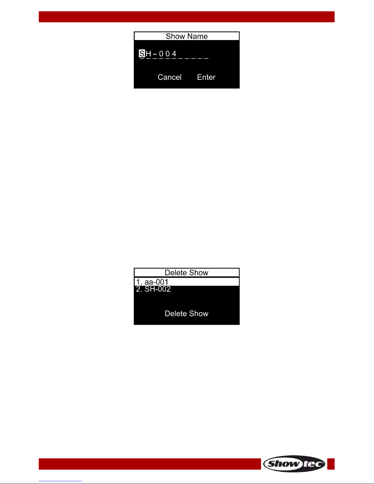
3. Delete Show
In this menu you can remove the previously recorded shows.
01) The display will show:
02) Press the UP/DOWN buttons to select the show which you would like to delete.
03) Press the ENTER button to confirm your choice. DELETE SHOW will illuminate.
04) Press the ENTER button to delete the show.
05) Repeat steps 2-4 to delete other shows.
06) If the show which you wish to delete is assigned to any active trigger event, the device will inform
you about this fact. Press the UP/DOWN buttons to choose CONTINUE (to delete the show) or RETURN
(to return to the previous menu) and press the ENTER button to confirm your choice.
Page 12

11
Ordercode: 50825
TR-512
4. Trigger Event
In this menu you can set the trigger event settings. It is possible to activate multiple triggers at a time.
01) The display will show:
02) Press the UP/DOWN buttons to select the desired trigger and press the ENTER button to open the
desired menu. The display will show:
03) Press the UP/DOWN buttons to toggle through the 5 available submenus:
● STATUS
● RENAME
● SHOW
● MODE
● DELAY
04) Press the ENTER button to open the desired submenu.
4.1. Status
In this menu you can activate/deactivate the desired trigger event.
01) Once you have entered the menu, press the UP/DOWN buttons to select ENABLE or DISABLE.
02) Press the ENTER button to confirm your choice.
4.2. Rename
In this menu you can rename the trigger events.
01) Once you have entered the menu, the display will show:
02) Press the UP/DOWN buttons to select the character which you would like to edit and press the ENTER
button.
03) Press (or press and hold down, for quick search) the UP/DOWN buttons to select the desired
character and press the ENTER button to confirm your choice. Repeat this step to edit the other
characters.
04) Once you have renamed the trigger event, press the UP/DOWN buttons to select CANCEL (to
discard changes) or ENTER (to confirm the new name). Press the ENTER button to confirm your
choice.
Page 13

12
Ordercode: 50825
TR-512
4.3. Show
In this menu you can assign your recorded shows to the desired triggers.
01) Once you have entered the menu, press the UP/DOWN buttons to select the desired show.
02) Press the ENTER button to confirm your choice.
4.4. Mode
In this menu you can set the trigger mode.
01) Once you have entered the menu, press the UP/DOWN buttons to select one of the 4 modes:
● NO_TR: Normally Open (Trigger will be activated when the circuit closes. As long as the circuit
remains closed, the triggered show will play in a loop. When the circuit opens, the show will keep
playing until it ends and then it will stop. With only a short pulse, the show will play just once.)
● NC_TR: Normally Closed (Trigger will be activated when the circuit opens. As long as the circuit
remains open, the triggered show will play in a loop. When the circuit closes, the show will keep
playing until it ends and then it will stop. With only a short pulse, the show will play just once.)
● TOGGLE_TR: It works with NO and NC circuits (external buttons). The first pulse starts the triggered
show to play in a loop. After the second pulse, the show will stop. Another pulse will restart the
show.
● AUTO_TR: When set to this mode, the trigger will be activated immediately. Upon every start-up,
the device will always search for any triggers set to this mode and will activate them.
02) Press the ENTER button to confirm your choice.
03) It is possible to use each of the 4 modes at the same time, independently, for separate triggers (1-6).
4.5. Delay
In this menu you can set the delay time.
01) Once you have entered the menu, press the UP/DOWN buttons to set the delay time. The adjustment
range is between 0-120 seconds.
02) Press the ENTER button to save changes.
Note: Once you have adjusted all the options 4.1-4.5, press the UP/DOWN buttons to select CONFIRM &
SAVE (to save a new trigger event) or CANCEL & RETURN (to discard changes and return to the previous
menu). Press the ENTER button to confirm your choice.
5. Stop TR Event
In this menu you can deactivate the desired trigger events.
01) The display will show:
02) Press the UP/DOWN buttons to select the desired trigger event.
03) Press the ENTER button to deactivate the selected trigger event.
04) Repeat steps 2-3 to deactivate the remaining trigger events.
Page 14
13
Ordercode: 50825
TR-512
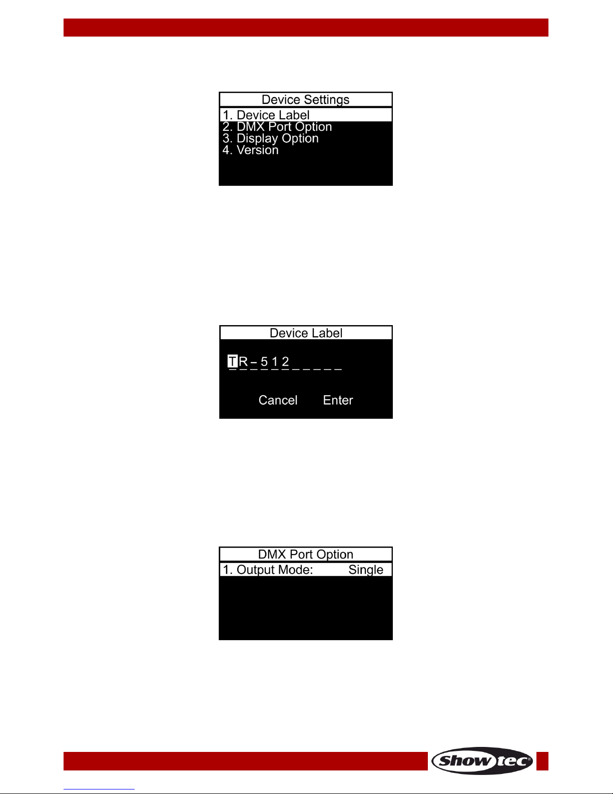
6. Device Settings
In this menu you can set the device’s settings.
01) The display will show:
02) Press the UP/DOWN buttons to toggle through the 4 available submenus:
● DEVICE LABEL
● DMX PORT OPTION
● DISPLAY OPTION
● VERSION
03) Press the ENTER button to open the desired submenu.
6.1. Device Label
In this menu you can rename the device label.
01) Once you have entered the menu, the display will show:
02) Press the UP/DOWN buttons to select the character which you would like to edit and press the ENTER
button.
03) Press (or press and hold down, for quick search) the UP/DOWN buttons to select the desired
character and press the ENTER button to confirm your choice. Repeat this step to edit the other
characters.
04) Once you have renamed the device label, press the UP/DOWN buttons to select CANCEL (to discard
changes) or ENTER (to confirm the new name). Press the ENTER button to confirm your choice.
6.2. DMX Port Option
In this menu you can set the port settings.
01) Once you have entered the menu, press the ENTER button to open edition mode.
02) Press the UP/DOWN buttons to select one of the 2 modes:
● SINGLE: only the last triggered show will be played
● HTP (Highest Takes Precedence): all triggered shows can be played simultaneously. The DMX
values of each DMX channel are compared for all the triggered shows and they become
merged into a DMX output signal, which contains only the highest value for each DMX channel.
03) Press the ENTER button to confirm your choice.
Page 15
14
Ordercode: 50825
TR-512
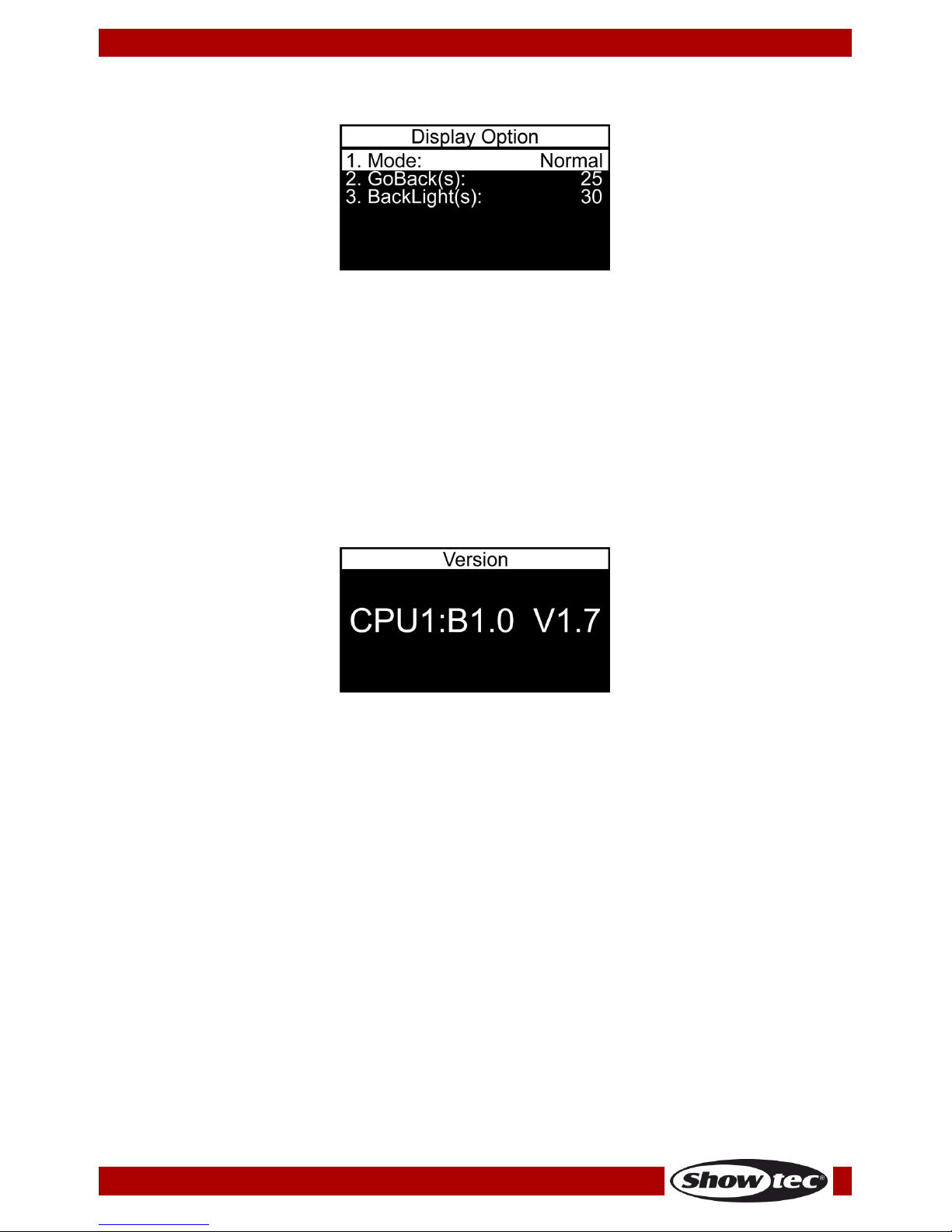
6.3. Display Option
In this menu you can set the display options.
01) Press the UP/DOWN buttons to select one of the 3 modes:
● MODE: choose between NORMAL (normal view) and INVERSE (display flip). If you have chosen
INVERSE, the button functions (MENU/UP/DOWN/ENTER) will flip accordingly, too.
● GOBACK(S): set the time which needs to pass, after which the display returns to the start screen,
when no button is pressed; the adjustment range is between NEVER and 5-60 seconds
● BACKLIGHT(S): set the time which needs to pass, after which the display will turn off; the
adjustment range is between ON and 5-60 seconds
02) Press the ENTER button to open the desired submenu.
03) Press the UP/DOWN buttons to adjust settings.
04) Press the ENTER button to save changes.
6.4. Version
In this menu you can view the current software version.
Page 16

15
Ordercode: 50825
TR-512
7. Save Configuration
In this menu you can create a configuration backup.
01) The display will show:
02) Once you have entered the menu, press the UP/DOWN buttons to select NAME and press the ENTER
button to open name edition menu. The display will show:
03) Press the UP/DOWN buttons to select the character which you would like to edit and press the ENTER
button.
04) Press (or press and hold down, for quick search) the UP/DOWN buttons to select the desired
character and press the ENTER button to confirm your choice. Repeat this step to edit the other
characters.
05) Once you have renamed the configuration file, press the UP/DOWN buttons to select CANCEL (to
discard changes) or ENTER (to confirm the new name). Press the ENTER button to confirm your
choice.
06) Now press the UP/DOWN buttons to select BACKUP DATA and press the ENTER button to create a
configuration backup. The display will show:
07) Press the ENTER button to return to the main menu.
Page 17

16
Ordercode: 50825
TR-512
8. Load Configuration
In this menu you can load or delete your configuration backup files.
01) The display will show:
02) Press the UP/DOWN buttons to select the desired configuration backup file. Press the ENTER button to
confirm your choice.
03) Press the UP/DOWN buttons to choose between RESTORE (load the desired configuration backup file)
and DEL (delete the desired configuration backup file). Press the ENTER button to confirm your
choice. Alternatively, press the MENU button if you do not want to use those functions and you want
to return to the previous menu.
9. Default Setting
In this menu you can restore default settings.
01) Once you have entered the menu, the display will show:
02) Press the UP/DOWN button to choose between YES and NO. Press the ENTER button to confirm your
choice.
03) If you have chosen NO, the display will return to the main menu.
04) If you have chosen YES, the default settings will be restored (All settings of the current trigger events
and all the display options will be set to default. The DMX PORT OPTION will be set to SINGLE.)
05) All saved shows and configuration files will remain intact.
06) The display will return to the main menu.
The TR-512 should be turned off, before removing the micro SD card.
The included micro SD card can be used to back up your data and transfer your files to a
regular PC.
Page 18

17
Ordercode: 50825
TR-512
RJ45 Connector
Please follow the instructions below in order to create an RJ45 trigger connector.
Fig. 04
It is possible to use each of the 4 modes (NO_TR, NC_TR, TOGGLE_TR, AUTO_TR) independently, for
separate triggers (1-6). Make sure that your settings are correct (see 4.4, page 12).
Maintenance
The Showtec TR-512 requires almost no maintenance. However, you should keep the unit clean.
Disconnect the mains power supply and then wipe the cover with a damp cloth. Do not use alcohol or
solvents. Do not immerse in liquid. Keep connections clean. Disconnect electric power, and then wipe
the DMX connections with a damp cloth. Make sure connections are thoroughly dry before linking
equipment or supplying electric power.
The operator has to make sure that safety-related and machine-technical installations are to be
inspected by an expert after every year in the course of an acceptance test.
The operator has to make sure that safety-related and machine-technical installations are to be
inspected by a skilled person once a year.
The following points have to be considered during the inspection:
01) All screws used for installing the device or parts of the device have to be tightly connected and must
not be corroded.
02) There may not be any deformations on housings, fixations and installation spots.
03) The electric power supply cables must not show any damages or material fatigue.
Page 19

18
Ordercode: 50825
TR-512
Troubleshooting
No Light
This troubleshooting guide is meant to help solve simple problems.
If a problem occurs, carry out the steps below in sequence until a solution is found. Once the unit
operates properly, do not carry out following steps.
If the DMX trigger or the light effect does not operate properly, refer servicing to a technician.
Suspect three potential problem areas as: the power supply, the DMX trigger and the light fixture.
01) Power supply. Check if the unit is plugged into an appropriate power supply.
02) The DMX trigger. Return the TR-512 to your Showtec dealer.
03) The light fixture. Return your light fixture to your dealer.
04) If all of the above appears to be O.K., plug the unit in again.
05) If you are unable to determine the cause of the problem, do not open the TR-512, as this may
damage the unit and the warranty will become void.
06) Return the device to your Showtec dealer.
No Response to DMX
Suspect the DMX cable or connectors, a controller malfunction, a light effect DMX card malfunction.
01) Check the DMX setting. Make sure that DMX addresses are correct.
02) Check the DMX cable: Unplug the unit; change the DMX cable; then reconnect to electrical power.
Try your DMX control again.
03) Determine whether the DMX trigger, light controller or light effect is at fault. Does the controller
operate properly with other DMX products? If not, take the controller in for repair. If so, take the DMX
cable and/or the light effect to a qualified technician.
Problem
Probable cause(s)
Remedy
The device does
not function at all
No power to the device
● Check if power is switched on and
cables are plugged in
Fixtures reset
correctly, but all
respond erratically
or not at all to the
controller
The controller is not connected
● Connect controller
3-pin XLR Out of the DMX trigger
does not match XLR Out of the
fixture on the link (i.e. signal is
reversed)
● Install a phase reversing cable
between the controller and the first
fixture on the link
Fixtures reset
correctly, but
some respond
erratically or not at
all to the DMX
trigger
Poor data quality
● Check data quality. If much lower than
100 percent, the problem may be a
bad data link connection, poor quality
or broken cables, missing termination
plug, or a defective fixture disturbing
the link
Bad data link connection
● Inspect connections and cables.
Correct poor connections. Repair or
replace damaged cables
Data link not terminated with 120
Ohm termination plug
● Insert termination plug in output jack of
the last fixture on the link
Incorrect addressing of the fixtures
● Check address setting
3-pin XLR Out on the fixtures does
not match (pins 2 and 3 reversed)
● Install a phase-reversing cable
between the fixtures or swap pins 2
and 3 in the fixture
No light or
LEDs/lamp cuts out
intermittently
Fixture is too hot
● Allow fixture to cool down
● Make sure air vents and front lens are
not blocked
● Turn up the air conditioning
LEDs/lamp damaged
● Disconnect fixture and return to your
dealer
The power supply settings do not
match local AC voltage and
frequency
● Disconnect fixture. Check settings and
correct if necessary
Page 20

19
Ordercode: 50825
TR-512
Product Specifications
Model:
Showtec TR-512
Input voltage:
100-240V AC, 50/60 Hz
Power supply:
12V DC via the included power adapter, 1500mA
Dimensions:
115 x 67 x 45 mm (LxWxH)
Weight:
0,4 kg
Operation and Programming
Signal pin OUT:
pin 1 GND, pin 2 (-), pin 3 (+)
Setup:
LCD display for easy setup
Signal input:
3-pin XLR IN
Signal output:
3-pin XLR OUT
Electro-mechanical effects
Control protocol:
DMX-512
Connections:
3-pin XLR IN & OUT, microSD card IN, trigger RJ45 IN (do not use for
data transmission)
Storage:
MicroSD card (included)
Housing:
Aluminum extrusion
IP rating:
IP20
Max. ambient temperature ta:
40°C
Max. housing temperature tB
80°C
Design and product specifications are subject to change without prior notice.
Website: www.Showtec.info
Email: service@highlite.nl
Page 21

20
Ordercode: 50825
TR-512
Dimensions
Page 22

21
Ordercode: 50825
TR-512
Notes
Page 23

22
Ordercode: 50825
TR-512
Page 24

©2017 Showtec
 Loading...