

Interface for
RGB LED Compact Studio Beam
ORDERCODE 42480
Interface 42480
Studio Beam Black 42474
Studio Beam Silver 42475

Congratulations!
You have bought a great, innovative product from Showtec.
The Showtec RGB Studio Beam Driver brings excitement to any venue. Whether you want simple plug-&play action or a sophisticated DMX show, this product provides the effect you need.
You can rely on Showtec, for more excellent lighting products.
We design and manufacture professional light equipment for the entertainment industry.
New products are being launched regularly. We work hard to keep you, our customer, satisfied.
For more information: iwant@showtec.info
You can get some of the best quality, best priced products on the market from Showtec.
So next time, turn to Showtec for more great lighting equipment.
Always get the best -- with Showtec !
Thank you!

1
2
3
3
3
4
4
4
4
5
6
7
7
7
7
8
8
8
8
8
9
9
10
11
12
12
12
13
Showtec
Showtec RGB Studio Beam Driver ™ Product Guide
Warning.................................................................................…...……………..…………………………….………..….
Safety-instructions…………………………………………………………………………………………………………
Operating Determinations.……………………………………………………………………………………………..
Rigging.……………………………………………………………………………………………………………………..
Description...............................................................................…...………………………………………….………..…
Features…….……………………………………………………………………………………….……...………………
Overview..…………………………………………………………………………………....................................…….
Installation...............................................................................…...…………………………………….…………….…..
Set Up and Operation.....................................................................……..……………………………….……………..
Control Menu Map.............................................................……..……………………………….…………………..
DMX Operation.............................................................……..……………………………….……………………….
Master/Slave Mode.............................................................……..……………………………….…………..……..
Stand-alone Operation.............................................................……..……………………………….……………..
Auto Chase Mode.............................................................……..……………………………….……………..
Manual Color Mixing .............................................................……..……………………………….…………..
Music Mode .............................................................……..……………………………….……………………..
DMX Protocol (3 Channel Mode) .............................................................………………………………………..
DMX Protocol (5 Channel Mode) .............................................................………………………………………..
DMX Protocol (6 Channel Mode) .............................................................………………………………………..
DMX Protocol (6 Channel Mode) .............................................................………………………………………..
DMX Protocol (15 Channel Mode) .............................................................………………………………………
DMX Protocol (30 Channel Mode) .............................................................………………………………………
Setting the DMX Control Mode.............................................................……..……….………….……………..….
Maintenance...................................................................................………..………….…….………………………….
Changing the Fuse........................................................................…………………….………………………..…..
Troubleshooting............................................................................………………….………………….………………..
Product Specifications.................................................................……………….…….………………………………..
2
WARNING
CAUTION!
Keep this device away from rain and moisture!
Unplug mains lead before opening the housing!
CAUTION! Be careful with your operations.
With a dangerous voltage you can suffer
a dangerous electric shock when touching the wires!
FOR YOUR OWN SAFETY, PLEASE READ THIS USER MANUAL CAREFULLY
BEFORE YOUR INITIAL START-UP!
SAFETY INSTRUCTIONS
Every person involved with the installation, operation and maintenance of this device has to:
- be qualified
- follow the instructions of this manual
Before your initial start-up, please make sure that there is no damage caused by transportation. Should
there be any, consult your dealer and do not use the device.
To maintain perfect condition and to ensure a safe operation, it is absolutely necessary for the user to
follow the safety instructions and warning notes written in this manual.
Please consider that damages caused by manual modifications to the device are not subject to
warranty.
This device contains no user-serviceable parts. Refer servicing to qualified technicians only.
IMPORTANT:
The manufacturer will not accept liability for any resulting damages caused by the nonobservance of this manual or any unauthorized modification to the device.
Never let the power-cord come into contact with other cables! Handle the power-cord and all
connections with the mains with particular caution!
Never remove warning or informative labels from the unit.
Do not open the device and do not modify the device.
Do not connect this device to a dimmerpack.
Do not switch the device on and off in short intervals, as this would reduce the system’s life.
Only use device indoor, avoid contact with water or other liquids.
Avoid flames and do not put close to flammable liquids or gases.
Always disconnect power from the mains, when device is not used or before cleaning! Only
handle the power-cord by the plug. Never pull out the plug by tugging the power-cord.
Make sure that the available voltage is not higher than stated on the rear panel.
Make sure that the power-cord is never crimped or damaged. Check the device and the power-
cord from time to time.
If device is dropped or struck, disconnect mains power supply immediately. Have a qualified
engineer inspect for safety before operating.
If the device has been exposed to drastic temperature fluctuation (e.g. after transportation), do
not switch it on immediately. The arising condensation water might damage your device. Leave
the device switched off until it has reached room temperature.
If your Showtec device fails to work properly, discontinue use immediately. Pack the unit securely
(preferably in the original packing material), and return it to your Showtec dealer for service.
For replacement use fuses of same type and rating only.
Repairs, servicing and electric connection must be carried out by a qualified technician.
WARRANTY: Till one year after date of purchase.
3
OPERATING DETERMINATIONS
International
EU Cable
UK Cable
US Cable
Pin
L
BROWN
RED
YELLOW/COPPER
FASE
N
BLUE
BLACK
SILVER
NUL
YELLOW/GREEN
GREEN
GREEN
EARTH
If this device is operated in any other way, than the one described in this manual, the product may suffer
damages and the warranty becomes void.
Any other operation may lead to dangers like short-circuit, burns, electric shock, lamp explosion, crash
etc.
You endanger your own safety and the safety of others!
Improper installation can cause serious damage to people and property !
Rigging
Please follow the European and national guidelines concerning rigging, trussing and all other
safety issues.
Do not attempt the installation yourself !
Always let the installation be carried out by an authorized dealer !
Procedure:
If the driver is lowered from the ceiling or high joists, professional trussing systems have to be used.
Use a clamp to mount the driver, with the mounting-bracket, to the trussing system.
The driver must never be fixed swinging freely in the room.
The installation must always be secured with a safety attachment, e.g. an appropriate safety net
or safety-cable.
When rigging, derigging or servicing the driver, always make sure, that the area below the
installation place is blocked and staying in the area is forbidden.
Connection with the mains
Connect the device to the mains with the power-plug.
Always pay attention, that the right color cable is connected to the right place.
Make sure that the device is always connected properly to the earth!

4
Description of the device
Features
The RGB Studio Beam Driver can control up to 10 LED Compact Studio Beams
• Output: Max. 10X 3W RGB LED Compact Studio Beam
• Output Connector: 5 Pole XLR female
• DMX IN and OUT
• Standalone
• DMX-512
• Stand – alone operation: Master/Slave.
Manual color mix, dimmer speed
16 Standalone programs
Music Controlled with Speed adjustment
• Fixture Settings: Mode-1: 3 Channels DMX
Mode-2: 5 Channels DMX
Mode-3: 6 Channels DMX
Mode-4: 15 Channels DMX
Mode-5: 30 Channels DMX
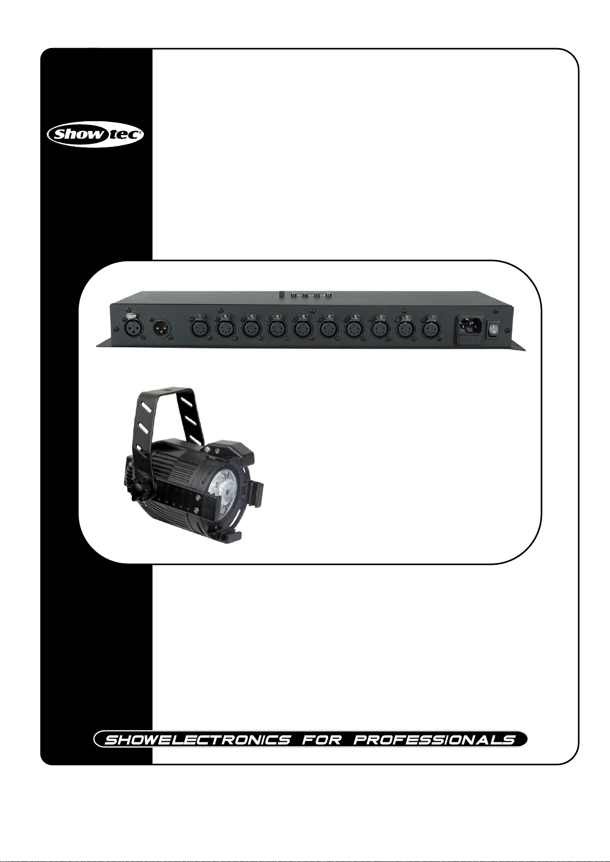
Overview
Fig. 1
1) 3-pin DMX OUT connector: XLR female socket used to send DMX signals.
2) 3-pin DMX IN connector: XLR male socket used to receive DMX signals.
3) 10X 5-pin connector for RGB Studio Beam
4) IEC Powerconnector + Fuse T3,15A 250V
5) ON/OFF
You can connect a maximum of 10 LED Compact Studio Beams to the controller.
Showtec LED Compact Studio Beam RGB Black incl. filterframe (42474)
Showtec LED Compact Studio Beam RGB Silver incl. filterframe (42475)
42474 42475
Installation
Remove all packing materials from the RGB Studio Beam Driver. Check that all foam and plastic padding
is removed. Connect all cables.
Always disconnect from electric mains power supply before cleaning or servicing.
Damages caused by non-observance are not subject to warranty.

5
Set Up and Operation
Follow the directions below, as they pertain to your preferred operation mode.
Before plugging the unit in, always make sure that the power supply matches the product specification
voltage. Do not attempt to operate a 120V specification product on 230V power, or vice versa.
You can operate this device as:
1. Stand-alone unit
2. DMX-controllable
After completing your settings, be sure to unplug the driver otherwise errors could occur.
This way you reset the entire system, but your settings keep stored in the memory of the driver.
DMX Serial Data Link
If you are using the standard DMX controller, you can connect the DMX output of the driver directly with
the DMX input of the first fixture in the DMX-chain. Connect the DMX output of first fixture in the chain with
DMX input of next fixture. Always connect one output with input of next fixture until all fixtures are
connected.
Wiring diagram Spots
Output connector: 5 Pole XLR
Pin-1 = Red colour
Pin-2 = Vcc
Pin-3 = Green colour
Pin-4 = Vcc
Pin-5 = Blue colour

6
Control Menu Map
DMX Mode - 3 DMX Channels
FUNCTIONS:
There are 5 options to operate the RGB Studio Beam Driver: DMX Mode
Auto Mode
Manual Mode
Music Mode
DMX Mode - 5 DMX Channels
DMX Mode - 6 DMX Channels
DMX Mode - 6 DMX Channels
DMX Mode - 15 DMX Channels
DMX Mode - 30 DMX Channels
Slave Mode
Auto Mode – Program 1 (Switch)
Auto Mode - Program 2 (Switch)
Auto Mode - Program 3 (Fade)
Auto Mode - Preset Colours
Manual Mode - Red Dimmer
Manual Mode - Green Dimmer
Manual Mode - Blue Dimmer
Music Mode
Master / Slave

7
DMX Operation
The RGB Studio Beam Driver will automatically detect the presence of a DMX signal.
In order to receive a DMX signal, the driver must be attached to a DMX controller by a 3-pin DMX cable
and the DMX controller must be turned on.
Addressing the Fixture
1) Press the MODE button to scroll though the menu. You can change the DMX address, when you are in
DMX Mode. You can choose 6 different DMX Modes.
2) Use the UP/ DOWN buttons to change the settings. Press the Save button to store your settings.
3) You can change the address from DMX Mode - 3 DMX Channels
DMX Mode - 5 DMX Channels
DMX Mode - 6 DMX Channels
DMX Mode - 6 DMX Channels
DMX Mode - 15 DMX Channels
DMX Mode - 30 DMX Channels
Master/Slave Mode
Only one fixture can be set as master device and the rest are slave devices.
1) Press the MODE button to scroll though the menu until the display shows
Note: The master and slaves devices must all have the same address in order to function the same.
Stand-alone Operation
Auto Mode
1) Press the MODE button to scroll though the menu until the display shows
Program 1 - 1-16 control the running speed.
Program 2 - 1-16 control the running speed.
Program 3 - Fade program. 1-16 control the running speed.
Preset Mode - Select one of the 7 preset color settings.
2) Press the MODE button to scroll through submenus and use the UP/ DOWN buttons to change the
settings. Press the Save button to store your settings.
Manual Mode
1) Press the MODE button to scroll though the menu until the display shows
Red Dimmer - Adjust the dimmer value by using the Up/Down buttons.
Green Dimmer - Adjust the dimmer value by using the Up/Down buttons.
Blue Dimmer - Adjust the dimmer value by using the Up/Down buttons.

8
Music Mode
0-255
Red 0 – 100%
0-255
Green 0 – 100%
0-255
Blue 0 – 100%
0-255
Red 0 – 100%
0-255
Green 0 – 100%
0-255
Blue 0 – 100%
0
Full On
1-255
0 – 100%
0-255
Strobe effect, from slow to fast
0-255
CH1 Red 0 – 100%
0-255
CH2 Green 0 – 100%
0-255
CH3 Blue 0 – 100%
0-255
CH4 Red 0 – 100%
0-255
CH5 Green 0 – 100%
0-255
CH6 Blue 0 – 100%
1) Press the MODE button to scroll though the menu until the display shows
2) You can use the Audio sensitivity control to adjust its sensitivity.
DMX Protocol (3 Channel Mode)
Channel 1 – Red
Channel 2 – Green
Channel 3 – Blue
DMX Protocol (5 Channel Mode)
Channel 1 – Red
Channel 2 – Green
Channel 3 – Blue
Channel 4 – Master Dimmer
Channel 5 – Master Strobe
DMX Protocol (6 Channel Mode)
DMX Channel 1 + 2 + 3 control RGB Output 2, 4, 6, 8 and 10
DMX Channel 4 + 5 + 6 control RGB Output 1, 3, 5, 7 and 9

9
0-255
CH1 Red 0 – 100%
0-255
CH2 Green 0 – 100%
0-255
CH3 Blue 0 – 100%
0-255
CH4 Red 0 – 100%
0-255
CH5 Green 0 – 100%
0-255
CH6 Blue 0 – 100%
0-255
CH1 Red 0 – 100%
0-255
CH2 Green 0 – 100%
0-255
CH3 Blue 0 – 100%
0-255
CH4 Red 0 – 100%
0-255
CH5 Green 0 – 100%
0-255
CH6 Blue 0 – 100%
0-255
CH7 Red 0 – 100%
0-255
CH8 Green 0 – 100%
0-255
CH9 Blue 0 – 100%
0-255
CH10 Red 0 – 100%
0-255
CH11 Green 0 – 100%
0-255
CH12 Blue 0 – 100%
0-255
CH13 Red 0 – 100%
0-255
CH14 Green 0 – 100%
0-255
CH15 Blue 0 – 100%
DMX Protocol (6 Channel Mode)
DMX Channel 1 + 2 + 3 control RGB Output 6 - 10
DMX Channel 4 + 5 + 6 control RGB Output 1 - 5
DMX Protocol (15 Channel Mode)
DMX Channels CH1 + CH2 + CH3 control RGB Output 9 and 10
DMX Channels CH4 + CH5 + CH6 control RGB Output 7 and 8
DMX Channels CH7 + CH8 + CH9 control RGB Output 5 and 6
DMX Channels CH10 + CH11 + CH12 control RGB Output 3 and 4
DMX Channels CH13 + CH14 + CH15 control RGB Output 1 and 2

10
0-255
CH1 Red 0 – 100%
0-255
CH2 Green 0 – 100%
0-255
CH3 Blue 0 – 100%
0-255
CH4 Red 0 – 100%
0-255
CH5 Green 0 – 100%
0-255
CH6 Blue 0 – 100%
0-255
CH7 Red 0 – 100%
0-255
CH8 Green 0 – 100%
0-255
CH9 Blue 0 – 100%
0-255
CH10 Red 0 – 100%
0-255
CH11 Green 0 – 100%
0-255
CH12 Blue 0 – 100%
0-255
CH13 Red 0 – 100%
0-255
CH14 Green 0 – 100%
0-255
CH15 Blue 0 – 100%
0-255
CH16 Red 0 – 100%
0-255
CH17 Green 0 – 100%
0-255
CH18 Blue 0 – 100%
0-255
CH19 Red 0 – 100%
0-255
CH20 Green 0 – 100%
0-255
CH21 Blue 0 – 100%
0-255
CH22 Red 0 – 100%
0-255
CH23 Green 0 – 100%
0-255
CH24 Blue 0 – 100%
0-255
CH25 Red 0 – 100%
0-255
CH26 Green 0 – 100%
0-255
CH27 Blue 0 – 100%
0-255
CH28 Red 0 – 100%
0-255
CH29 Green 0 – 100%
0-255
CH30 Blue 0 – 100%
DMX Protocol (30 Channel Mode)
DMX Channels CH1 + CH2 + CH3 control RGB Output 10
DMX Channels CH4 + CH5 + CH6 control RGB Output 9
DMX Channels CH7 + CH8 + CH9 control RGB Output 8
DMX Channels CH10 + CH11 + CH12 control RGB Output 7
DMX Channels CH13 + CH14 + CH15 control RGB Output 6
DMX Channels CH16 + CH17 + CH18 control RGB Output 5
DMX Channels CH19 + CH20 + CH21 control RGB Output 4
DMX Channels CH22 + CH23 + CH24 control RGB Output 3
DMX Channels CH25 + CH26 + CH27 control RGB Output 2
DMX Channels CH28 + CH29 + CH30 control RGB Output 1

11
Setting the DMX Control Mode
1) Use the UP/ DOWN buttons to choose one of the DMX control modes.
3 Channel DMX Mode
1 2 3 4 5 6 7 8 9 10
CH1 Red
CH2 Green
CH3 Blue
5 Channel DMX Mode
1 2 3 4 5 6 7 8 9 10
CH1 Red
CH2 Green
CH3 Blue
CH4 Master Dimmer
CH5 Master Strobe
6 Channel DMX Mode
1 2 3 4 5 6 7 8 9 10
CH4 R CH1 R CH4 R CH1 R CH4 R CH1 R CH4 R CH1 R CH4 R CH1 R
CH5 G CH2 G CH5 G CH2 G CH5 G CH2 G CH5 G CH2 G CH5 G CH2 G
CH6 B CH3 B CH6 B CH3 B CH6 B CH3 B CH6 B CH3 B CH6 B CH3 B
6 Channel DMX Mode
1 2 3 4 5 6 7 8 9 10
CH4 R CH4 R CH4 R CH4 R CH4 R CH1 R CH1 R CH1 R CH1 R CH1 R
CH5 G CH5 G CH5 G CH5 G CH5 G CH2 G CH2 G CH2 G CH2 G CH2 G
CH6 B CH6 B CH6 B CH6 B CH6 B CH3 B CH3 B CH3 B CH3 B CH3 B
15 Channel DMX Mode
1 2 3 4 5 6 7 8 9 10
CH13 R CH13 R CH10 R CH10 R CH7 R CH7 R CH4 R CH4 R CH1 R CH1 R
CH14 G CH14 G CH11 G CH11 G CH8 G CH8 G CH5 G CH5 G CH2 G CH2 G
CH15 B CH15 B CH12 B CH12 B CH9 B CH9 B CH6 B CH6 B CH3 B CH3 B

12
30 Channel DMX Mode
1 2 3 4 5 6 7 8 9 10
CH28 R CH25 R CH22 R CH19 R CH16 R CH13 R CH10 R CH7 R CH4 R CH1 R
CH29 G CH26 G CH23 G CH20 G CH17 G CH14 G CH11 G CH8 G CH5 G CH2 G
CH30 B CH27 B CH24 B CH21 B CH18 B CH15 B CH12 B CH9 B CH6 B CH3 B
Maintenance
The RGB Studio Beam Driver requires almost no maintenance. However, you should keep the unit clean.
Disconnect the mains power supply, and then wipe the cover with a damp cloth. Do not immerse in
liquid.
Keep connections clean. Disconnect electric power, and then wipe the connections with a damp cloth.
Make sure connections are thoroughly dry before linking equipment or supplying electric power.
Replacing a Fuse
Power surges, short-circuit or inappropriate electrical power supply may cause a fuse to burn out. If the
fuse burns out, the product will not function whatsoever. If this happens, follow the directions below to do
so.
1. Unplug the unit from electric power source.
2. Insert a flat-head screwdriver into a slot in the fuse cover. Gently pry up the fuse cover. The fuse will
come out.
3. Remove the broken fuse. If brown or unclear, it is burned out.
4. Insert the replacement fuse into the holder where the old fuse was. Reinsert the fuse cover.
Be sure to use a fuse of the same type and specification. See the product specification label for
details.
Troubleshooting
Showtec RGB Studio Beam Driver
This troubleshooting guide is meant to help solve simple problems.
If a problem occurs, carry out the steps below in sequence until a solution is found. Once the unit
operates properly, do not carry out following steps.
If the light effect does not operate properly, refer servicing to a technician.
1. If the device does not operate properly, unplug the device.
2. Check the fuse, power from the wall, all cables etc.
3. If all of the above appears to be O.K., plug the unit in again.
4. If you are unable to determine the cause of the problem, do not open the RGB Studio Beam Driver, as
This may damage the unit and the warranty will become void.
5. Return the device to your Showtec dealer.

13
Product Specification
Input Voltage:
AC 100 – 240V 50-60Hz
Power Consumption:
75W
Fuse:
F3,15A 250V
Protocol:
USITT DMX 512
DMX Channels:
3, 5, 6, 15, 30
Control Options:
DMX
Master/Slave
Auto Mode
Manual Mode
Music Mode
Power:
IEC
DMX:
XLR 3-PIN
Fixture output:
10X3W 5-PIN XLR Connector
LxWxH:
482x178x50mm
Weight:
2,64 Kg
Power
Power Consumption:
3W
Fixture output:
1,4m cable incl. 5-PIN XLR Connector
LxWxH:
125x110x120mm
Weight:
0,42 Kg
Model: Showtec RGB Studio Beam Driver (42480)
Power
Control and Programming
Connections
Dimensions and Weight
Model: Showtec LED Compact Studio Beam RGB Black (42474)
Showtec LED Compact Studio Beam RGB Silver (42475)
Connections
Dimensions and Weight
Max. ambient temperature ta: 40°C
Minimum distance:
Minimum distance from flammable surfaces: 0.5m
Minimum distance to lighted object: 1m
Design and product specifications are subject to change without prior notice.
Website: www.Showtec.info
Email: service@highlite.nl

 Loading...