

Page 1
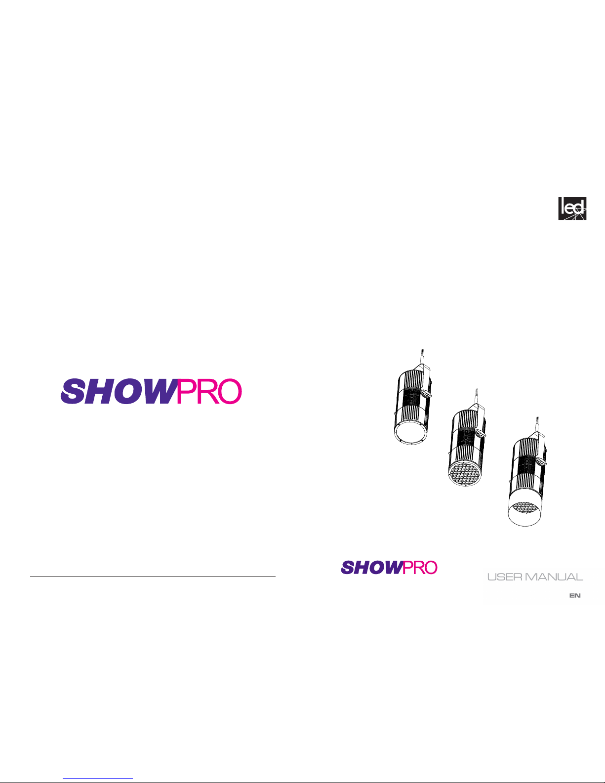
Warm White COB LED House Light
LED House Light
www.showtech.com.au
www.showtech.com.au
Page 2
LED House Light
2
SAFETY
General instruction
• The products referred to in this manual conform to the European Community Directives and are therefore marked with
.
• The unit is supplied with hazardous network voltage (230V~). Leave servicing to skilled personnel only.
Never make
risk an electric shock.
•
cording to standard EN 60598-1). It is, moreover, recommended to protect the supply lines of the units
from indirect contact and/or shorting to earth by using appropriately sized residual current devices.
installer. Check that the main frequency and voltage correspond to those for which the unit is designed
as given on the electrical data label.
• This unit is not for home use, only professional applications.
- in places subject to vibrations or bumps;
- in places with a temperature of over 40 °C.
an inspection or contact the manufacturer directly.
plant for a disposal which is not harmful to the environment.
Warnings and installation precautions
damage and the guarantee becomes void. Furthermore, any other operation may lead to dangers like
short circuit, burns, electric shock, etc.
• Always additionally secure the projector with the safety rope. When carrying out any work, always comply scrupulously with all the regulations (particularly regarding safety) currently in force in the country
• Shields, lenses or ultraviolet screens shall be changed if they have become damaged to such an extent
• The lamp (LED) shall be changed if it has become damaged or thermally deformed.
trigger epileptic seizures in photosensitive persons or persons with epilepsy.
• Do not touch the product’s housing when operating because it may be very hot.
WARNING! Before carrying out any operations with the unit, carefully read this instruction
manual and keep it with cure for future reference. It contains important information about
the installation, usage and maintenance of the unit.
19
Page 3

LED House Light
3
Packing content
LED House Light
• Mounting bracket
• 42°, 30°, and 15° Lenses
• User manual
TABLE OF CONTENTS
Safety
General instructions
Warnings and installation precautions
General information
1 Introduction
1. 1 Description and Technical specications
1. 3 Operating elements and connections
2 Installation
2. 1 Dimensions
2.2 Mounting
1.2 Maintenance
Cleaning the unit
Trouble shooting
3 Functions and settings
3. 1 Operation
3. 2 Basic
3. 3 Menu structure
3. 4 Auto show
3. 5 Static mode
3. 6 Master/Slave mode
3. 7 Linking
3. 8 DMX conguration
3. 9 DMX addressing
3. 10 Connection of the DMX line
3. 11 Construction of the DMX termination
3. 12 DMX control
3. 13 Photometrics
3. 14 Fixture settings
3. 15 Fixture information
18
Page 4
LED House Light
4
INTRODUCTION
This LED House Light produces a consistent warm white output from a state-of-the-art COB LED
source suitable for live and broadcast applications.
FEATURES
- Silent operation due to advanced convection cooled design
- Adjustable PWM frequency ensures icker-free, camera-safe performance
- Removable yoke and permanent cable anchor for pendant suspension mounting
- Three Interchangeable lenses to match beam angle to mounted height
- Optional Egg crate diuser and Top hat accessories
- Ultra-smooth dimming
- DMX, RDM control
SPECIFICATIONS
Light Source: 230W COB LED
White Color Temperature: 3160K
CRI: 93
Lens options: 15°, 30°, 42°
Photometrics: See photometrics chart
Strobe: 0-25Hz and strobe FX macros
Dimming: 4 dimming curve modes
Control: DMX
DMX Channels: 2 / 3 / 5
Display: OLED menu display
Mains: 100 - 240 VAC, 50/60 Hz
Consumption: 120W
Power connections: Hard-wired
Data connections: 5-pin XLR and terminal blocks for DMX
Housing: White or Black
IP rating: IP20
Cooling: Convection (fanless)
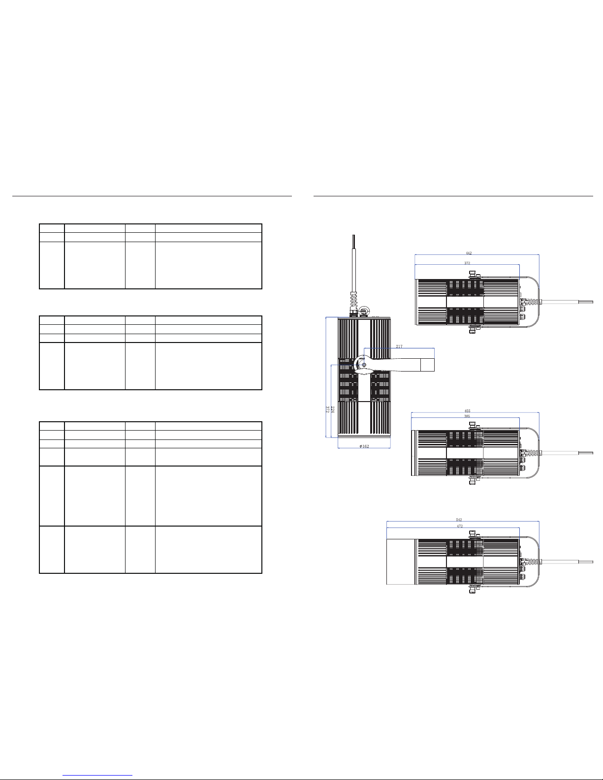
Dimensions (diameter): 162mm
Length: 442mm
Length with Egg crate: 455mm
Length with Egg crate + Top hat: 542mm
Weight: 6.3 KG
ORDER CODES
LEDPAR330 LED House Light White WW
LEDPAR331 LED House Light Black WW
Optional accessories:
LEDPAR335 LED House Light Crate Black
LEDPAR336 LED House Light Top Hat White
LEDPAR337 LED House Light Top Hat Black
17
LED House Light
3.15 FIXTURE INFORMATION
Fixture Hours
• Press the button MENU so many times until shows Information.
• Using the button UP/DOWN to select Fixture Hours,
• Then the display will show the working hours.
Version
• Press the button MENU so many times until shows Information
• Select through the button UP/DOWN the Version menu voice.
Temperature
• To read the value of the internal temperature of the device, press the MENU button repeatedly until
the display shows Temperature, and then press the ENTER button to read the value.
• Press the MENU button to go back or wait a few seconds to exit the setup menu.
Press MENU to return to main menu
Press MENU to return to main menu
Auto / Test
• To initiate the Auto Test function, press the MENU button repeatedly until Auto is displayed,
then press ENTER to until Test is displayed, then press ENTER to run the Auto Test program.
• Press the MENU button to go back or wait a few seconds to exit the setup menu.
Emergency Mode
• When Emergency Mode is ON, no action is taken if the DMX signal is lost.
• When Emergency Mode is OFF, the xture will turn on when DMX signal is lost.
3.14 FIXTURE SETTINGS
It is possible to change the following parameters:
Dimmer Mode
Press the MENU button until Dimmer Mode is displayed, then press ENTER.
• Press UP/DOWN buttons to select
• Press ENTER button to store, then press MENU to return to main menu.
BackLite
• To adjust the settings of the backlit menu display, press MENU until Back Light is shown.
• Press ENTER and then use UP/DOWN to select On or auto display o delay On - 10S - 20S - 30S
LED Frequency
• To adjust the frequency of the LEDs, press the MENU button repeatedly until the display shows LED
Frequency, and then press the ENTER button.
• Select the frequency (600 Hz - 25 kHz) using the UP/DOWN buttons.
, then press MENU to return to main menu.
, then press MENU to return to main menu
Page 5
LED House Light
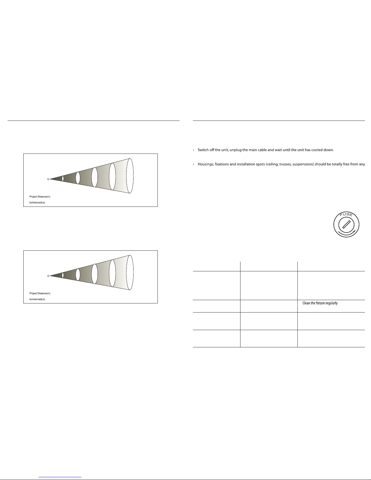
FUSE REPLACEMENT
1. Disconnect this product from the power outlet.
2. Using a screwdriver, unscrew the fuse holder cap from the housing.
3. Remove the blown fuse and replace with a good fuse of the same type and rating (250V/T2A).
4. Screw the fuse holder cap back in place and reconnect power.
Fig.8
5
- 1.2 - MAINTENANCE
MAINTENANCE AND CLEANING THE UNIT
• Make sure the area below the installation place is free from unwanted persons during setup.
• All screws used for installing the device and any of its parts should be tightly fastened and should not
be corroded.
deformation.
• The main cables must be in impeccable condition and should be replaced immediately even when a
small problem is detected.
• It is recommended to clean the front at regular intervals, from impurities caused by dust, smoke, or
other particles to ensure that the light is radiated at maximum brightness. For cleaning, disconnect the
main plug from the socket. Use a soft, clean cloth moistened with a mild detergent. Then carefully wipe
the part dr y. For cleaning other housing parts use only a soft, clean cloth. Never use a liquid, it might
penetrate the unit and cause damage to it.
TROUBLESHOOTING
Problems Possible causes Checks and remedies
Fixture does not light up
•
No mains supply
• Dimmer fader set to 0
• All color faders set to 0
• Faulty LED
• Faulty LED board
• Check the power supply voltage
•
Increase the value of the dimmer channels
• Increase the value of the color channels
•
Replace the LED board
• Replace the LED board
General low light intensity
• Dirty lens assembly
• Misaligned lens assembly
•
• Install lens assembly properly
Fixture does not power up
•
No power
•
Loose or damaged power cord
•
Faulty internal power supply
• Check for power on power outlet
•
Check power cord
• Replace internal power supply
Fixture does not respond to DMX
• Wrong DMX addressing
• Damaged DMX cables
•
Bouncing signals
•
Check control panel and unit addressing
• Check DMX cables
• Install terminator as suggested
Contact an authorized service center in case of technical problems or not reported in the table can not be
resolved by the procedure given in the table.
LED House Light
16
3.13 PHOTOMETRICS (cont’d)
Beam Angle:
32°
Full
18886 lux 2098 l ux
755 lux
1m
3m
5m
30° lens installed
lu385 x7m189 lu x
10m
Beam Angle:
41°
Full
10549 lux 1172 l ux
422 lu x
1m
3m
5m
42° lens installed
lu215 x
7m
105 lu x
10m
Page 6
LED House Light
6
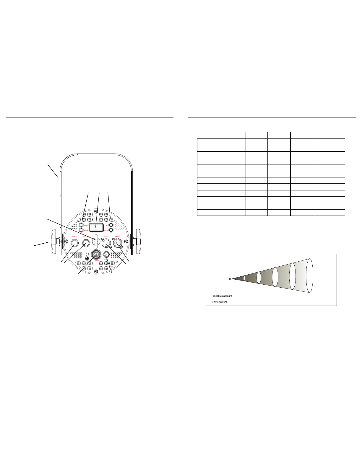
1.3 OPERATING ELEMENTS AND CONNECTIONS
5-pin
DMX In/Out
Mounting
bracket
Bracket
locking
knob
OLED display and
Menu navigation
Power In
Safety cable
anchor
Terminal blocks for
DMX In/Out
Fuse
LED House Light
15
3.13 PHOTOMETRICS
Beam Angle:
16°
Full
48359 lux 5393 l ux
1942 lu x
1m
3m
5m
Beam angle Field angle Lumens Lux @ 5 meters
15° lens 16° 28° 7183 1942
15° lens + Egg crate : 14° 26° 4505 1771
15° lens + Top hat 15° 26° 5789 1972
15° lens + Top hat + Egg crate : 14° 25° 4170 1891
30° lens 32° 49° 6784 755
30° lens + Egg crate: 24° 45° 4182 688
30° lens + Top hat 28° 42° 4726 743
30° lens + Top hat + Egg crate : 23° 39° 3349 709
42° lens 41° 71° 6565 422
42° lens + Egg crate 30° 61° 3602 392
42° lens + Top hat 32° 52° 3782 429
42° lens + Top hat + Egg crate : 26° 46° 2519 405
15° lens installed
lu991 x7m485 lu x
10m
Page 7
LED House Light
7
2.1 DIMENSIONS
LENGTH with lens attached
LENGTH with egg crate diuser attached
LENGTH with crate + top hat attached
LED House Light
14
3.12 DMX CONTROL
2 CHANNEL MODE
3 CHANNEL MODE
5 CHANNEL MODE
Function Valu e Percent /Setting
1 D immer 000-255 0 ~100%
2 LED Frequency
000-010
011-050
051-100
101-150
151-200
201-255
Preset LED Frequency from display menu
600Hz
1200Hz
2000Hz
4000Hz
25KHz
Functio n
Value
Percent /Setting
1
Dimmer-H
000-255
0~100% 2 Dimmer-L
000-255
0~100%
3 LED Frequency
000-010
011-050
051-100
101-150
151-200
201-255
Preset LED Frequency from display menu
600Hz
1200Hz
2000Hz
4000Hz
25KHz
Functio n
Value
Percent /Setting
1
Dimmer-H
000-255
0~100% 2 Dimmer-L
000-255
0~100%
3 S trobe Rat e
000-005
006-255
No func tion
Strobe s low to fast
4 S trobe FX
000-005
006-042
043-085
086-128
129-171
172-214
215-255
No e ect
Ram p up
Ram p down
Ram p up-down
Random
Lightni ng
Spike s
5 LED Frequency
000-010
011-050
051-100
101-150
151-200
201-255
Preset LED Frequency from display menu
600Hz
1200Hz
2000Hz
4000Hz
25KHz
(16 Bit)
(16 bit)
Page 8
LED House Light
8
- 2 - INSTALLATION
2.2 MOUNTING
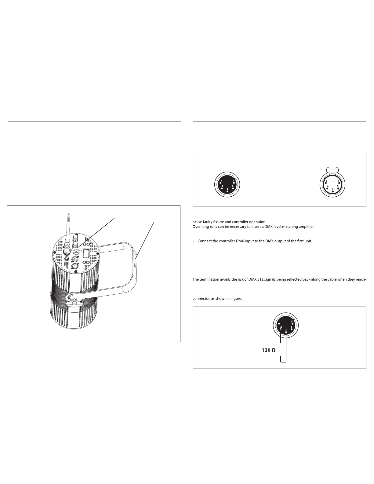
This xture may be mounted in two ways:
Pendant mounting: To suspend the xture vertically, attach a suspension cable directly to the anchor
located at the center of the back panel (1). In this conguration, the mounting bracket (2) should be
removed.
Clamp mounting: To mount the xture overhead with a clamp, attach a mounting clamp to the
mounting bracket (2). In this conguration, a safety cable should also be attached to the anchor (1)
as safety measure to prevent the xture from accidentally falling.
All mounting clamps and cables should be properly rated to bear the weight of the xture.
1
2
LED House Light
13
3.10 CONNECTION OF THE DMX LINE
DMX connection employs standard XLR connectors. Use shielded pair-twisted cables with 120Ω impedance and low capacity.
The following diagram shows the connection mode:
ATTENTION
The screened parts of the cable (sleeve) must never be connected to the system’s earth, as this would
For those connections the use of balanced microphone cable is not recommended because it cannot
transmit control DMX data reliably.
• Connect the DMX output to the DMX input of the following unit. Connect again the output to the input
of the following unit until all the units are connected in chain.
• When the signal cable has to run longer distance is recommended to insert a DMX termination on the
last unit.
3.11 CONSTRUCTION OF THE DMX TERMINATION
es the end of the line: under certain conditions and with certain cable lengths, this could cause them to
cancel the original signals.
The termination is prepared by soldering a 120Ω 1/4 W resistor between pins 2 and 3 of the 5-pin male XLR
DMX - OUTPUT
XLR socket
DMX - INPUT
XLR plug
Pin1 : GND - Shield
Pin2 : - Negative
Pin3 : + Positive
Pin4 : N/C
Pin5 : N/C
Page 9
LED House Light
9
- 3 - FUNCTIONS AND SETTINGS
3.1 OPERATION
Wire the power cable to power (100~240V/50~60Hz) according to the below table:
Connection Wire (U.S.) Wire (Europe) Screw color
AC Live Black Brown Yellow or Brass
AC Neutral White Blue Silver
AC Ground Green/Yellow Green/Yellow Green
3.2 BASIC
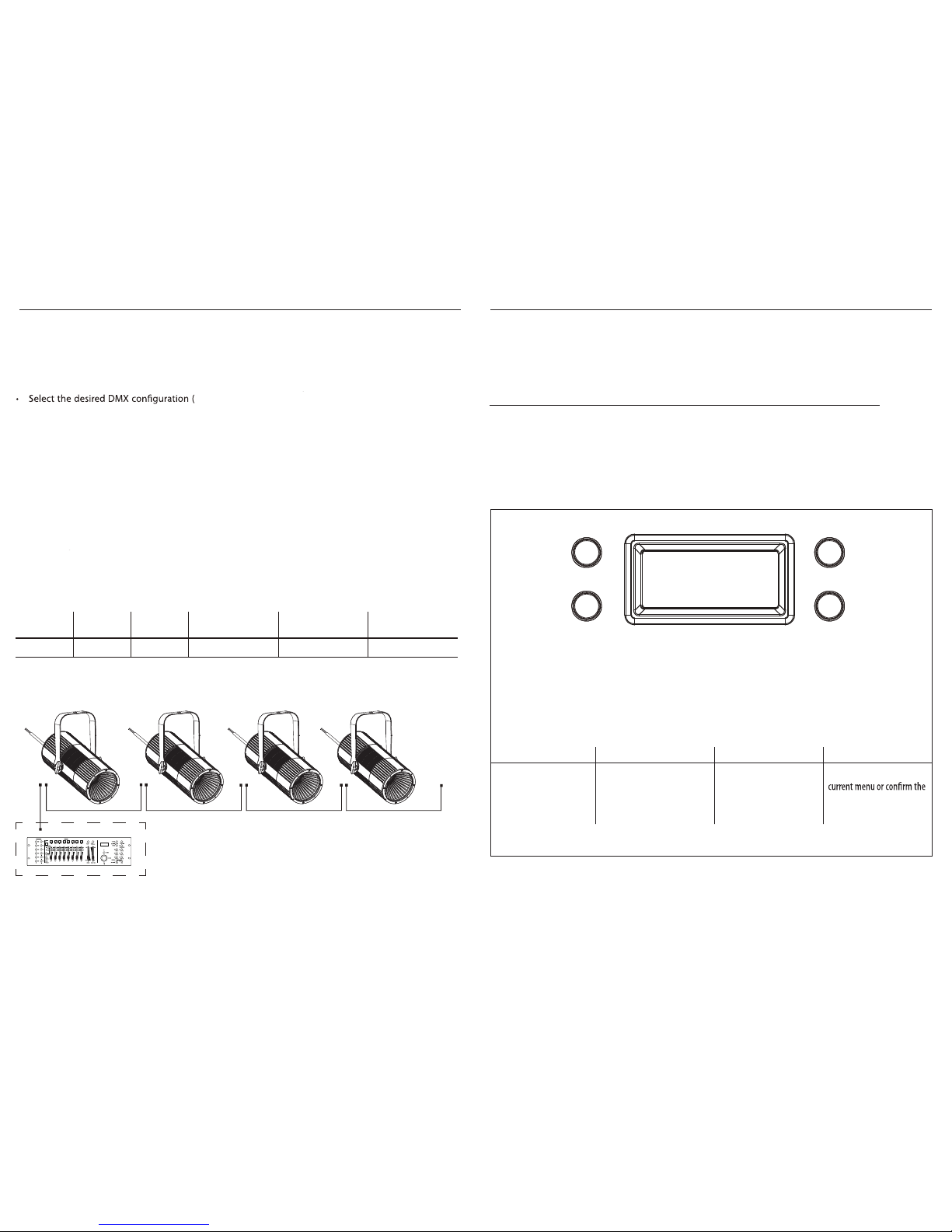
Access control panel functions using the four panel buttons located adjacent to the OLED display.
MENU UP DOWN ENTER
Used to access the menu or
to return a previous menu
option
Navigates downwards through
the menu list and increases
the numeric value when in a
function
Navigates upwards through
the menu list and decreases
the numeric value when in
a function
Used to select and store the
current function value or
option within a menu
UP
ENTER
MENU
DOWN
LED House Light
12
3.8 DMX CONFIGURATION
• Press the MENU button until is displayed, then press the ENTER button to conrm. [DMX CHANNEL]
2CH - 3CH - 5CH ) using the UP/DOWN buttons.
3.9 DMX ADDRESSING
• Press the MENU button until is displayed, then press ENTER to conrm. [DMX ADDRESS]
• Press UP/DOWN button to select the desired value (001-512). Press and hold to scroll quickly.
• Press the ENTER button to store.
An example conguration with the starting address of 33 in two-channel mode is shown below:
Number of
DMX channels
Start address
(example)
DMX Address
occupied
Next possible start
address for unit No. 1
Next possible start
address for unit No. 2
Next possible start
address for unit No. 3
DMX512 C ontroller
DMX Addre ss: 33 DMX Ad dress: 39DMX Address: 35 DMX Addre ss: 37
. . . . . . . . . . . .
Example 2-channel mode DMX confi guration
This xture oers three dierent DMX modes:
2 33 33-34 35 37 39
Page 10
LED House Light
10
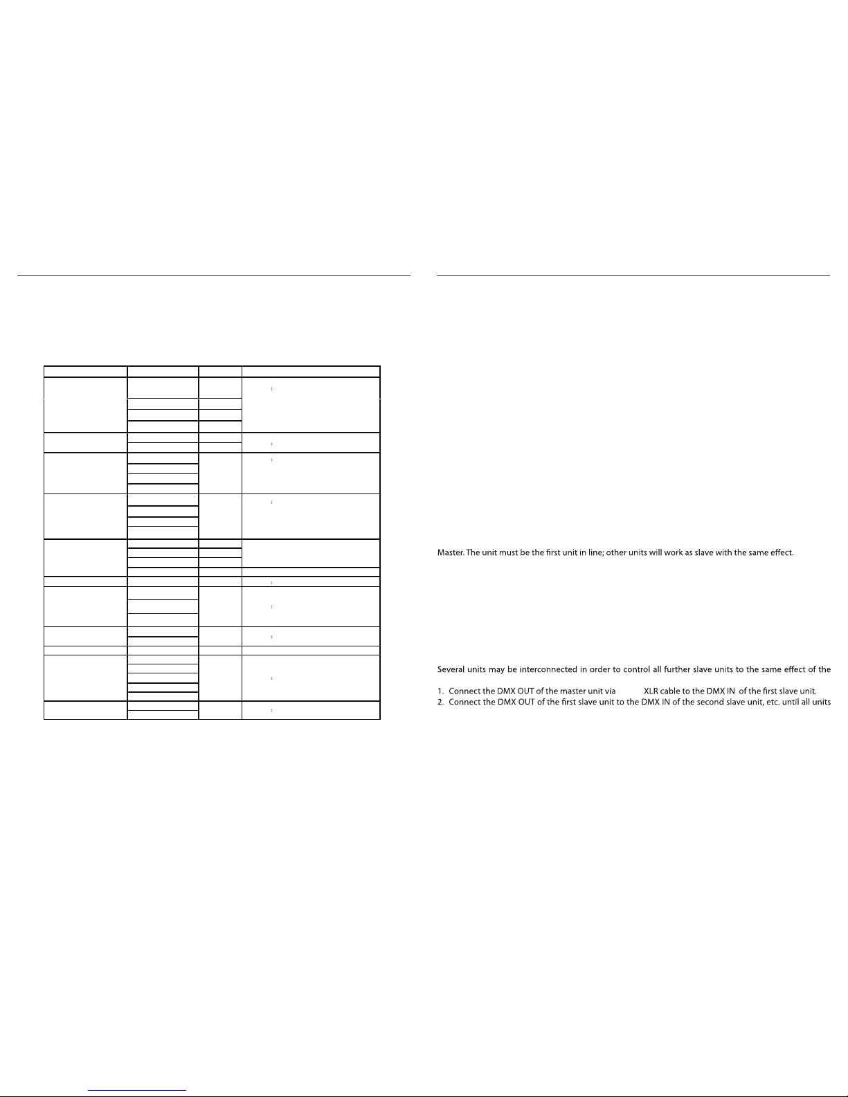
3.3 MENU STRUCTURE
Main Menu Submenu Submenu Rema rk
Auto Show
Defa ult Aut o 0; Speed : 100
<Aut o 0> <0 ~100 >
<Aut o 1> <0 ~100 >
<Aut o 2> <0 ~100 >
Static
<Dimme r>
<0 ~255>
Defa ult
Dimme r=255; Strobe=0
<Strobe>
< 0 ~ 255>
Dimmer Mode
<O>
Defa ult
0FF
<Dimme r 1>
<Dimme r 2>
<Dimme r 3>
Back L ight
<On>
Defa ult On
<10S>
<20S>
<30S>
Infor mation
Auto Test
Fixtu re Hours
<9999>
Version <V1. 0> UID:030F002FFFFF
Unit ID
DMX Address
1-512 Defa ult 001
DMX Channel
<2Ch>
Defa ult 5CH <3Ch>
<5Ch>
Mast er/Slave
<Ma ster>
Defa ult Slav e
<Slave> Temper ature
xx°
LED Fre quency
600Hz
Defa ult 1200HZ
1200 Hz
2000 Hz
4000 Hz
25KHz
Emer gency M ode
<On>
Defa ult On (xture turns on if DMX lost)
<O>
Selects auto program
and program speed
Dimmer 1 = fast dimming curve speed
Dimmer 2 = medium dimming speed
Dimmer 3 = slow dimming curve speed
10S = 10 second delay before display o
20S = 20 second delay before display o
30S = 30 second delay before display o
Turns on all LEDs in sequence for testing
Shows total xture runtime
Shows installed rmware version
Displays xture operating temperature
Selects PWM frequency
LED House Light
11
3.4 AUTO SHOW
If DMX control is not being used, the unit can run its onboard auto show programs:
• Press the MENU button until the display shows Auto Show, then press the ENTER button.
• Press the UP/DOWN buttons to switch between the show (Auto 0 - 2). The unit will operate in show mode.
• Use the UP/DOWN buttons to select the desired run speed slow-fast (0-100).
• Press the ENTER button to save the setting.
3.5 STATIC MODE
• To enable the static mode, press MENU repeatedly until Static shows on the display.
• Press the ENTER button.
• Select Dimmer, then press the ENTER button.
• Select the desired dimmer level (0~255) using the UP/DOWN buttons.
• Press the ENTER to save the dimmer setting.
• Follow similar steps to select and save Strobe settings.
3.6 MASTER/SLAVE MODE
This mode will allow you to link up the units together without a controller. Choose a unit to function as the
• Press the button MENU so many times until the display shows Master/Slave and press the button ENTER.
• Press UP/DOWN to set the unit as master or slave (Master/Slave).
• Select the desired program (see section 3.4).
• Use standard DMX cables to daisy chain your units together via the DMX connector on the rear of the
unit. For longer cable runs, using a DMX terminator as described in this manual is recommended.
3.7 LINKING
master unit.
are connected in a chain.
5-pin
If DMX control is not being used, the dimming and strobe levels can be set using the onboard menu:
<Auto 3>
<0 ~100 >
 Loading...