

Show UP-88H/8H, UR-82DR, UP-88P/8P User Manual
RR
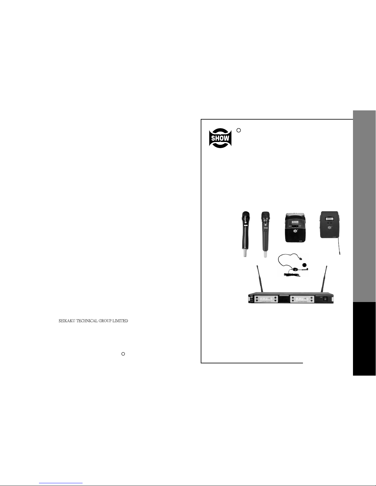
WIRELESS
MICROPHONE
SYSTEM
www.show-pa.com
UR-82DR SERIES
No.1, Lane 17, Sec. 2, Han Shi West Road, Taichung, 401 TAIWAN
Tel:886-4-22313737 Fax:886-4-22346757
http://www.show-pa.com e-mail: sekaku@sekaku.com
All rights reserved to SEIKAKU. All features and content might be changed
without prior notice. Any photocopy, translation, or reproduction of part of this
manual without written permission is forbidden. Copyright 2006 SEIKAKU GROUP
cc
UP- 8H /8P88H/ /88P
WIRELESS MICROPHONE SYSTEM
User's Manual
NF02763-1.0

IMPORTANT!
Please read this manual carefully before operating
this unit for the first time.
All rights reserved to SHOW. All features and content might be changed
without prior notice. Any photocopy, translation, or reproduction of part of
this manual without written permission is forbidden.
SAFETY RELATED SYMBOLS
CAUTION
RISK OF ELECTRIC SHOCK
DO NOT OPEN
The symbol is used to indicate that some
hazardous live terminals are involved
within this apparatus, even under the
normal operating conditions.
The symbol is used in the service documentation to indicate that specific
component shall be only replaced by
the component specified in that documentation for safety reasons.
Protective grounding terminal.
Alternating current /voltage.
ON: Denotes the apparatus turns on.
OFF: Denotes the apparatus turns off, be-
cause of using the single pole switch, be sure
to unplug the AC power to prevent any electric shock before you proceed your service.
WARNING: Describes precautions that
should be observed to prevent the danger
of injury or death to the user.
CAUTION: Describes precautions that
should be observed to prevent danger of the
apparatus.
WARNING
Power Supply
Ensure the source voltage matches the
voltage of the power supply b efore turning
ON the apparatus.
Unplug this apparatus during lightning
storms or when unused for long periods
of time.
External Connection
The external wiring connected to the output hazardous live terminals requires
installation by an instructed person, or
the use of ready-made leads or cords.
Do not Remove any Cover
There are maybe some areas with high
voltages inside, to reduce the risk of electric
shock, do not remove any cover if the power
supply is connected.
The cover should be removed by the qualified personnel only.
No user serviceable parts inside.
Fuse
To prevent a fire, make sure to use fuses
with specified standard (current, voltage,
type). Do not use a different fuse or short
circuit the fuse holder.
Before replacing the fuse, turn OFF the
apparatus and disconnected the power
source.
Protective Grounding
Make sure to connect the protective
grounding to prevent any electric shock
before turning ON the apparatus.
Never cut off the internal or external protective grounding wire or disconnect the
wiring of protective grounding terminal.
Operating Conditions
This apparatus shall not be exposed to
dripping or splashing and that no objects
filled with liquids, such as vases, shall be
placed on this apparatus.
To reduce the risk of fire or electric shock,
do not expose this apparatus to rain or
moisture.
Do not use this apparatus near water.
Install in accordance with the manufacturer's
Hazardous live terminal .
Disposing of this product should
not be placed in municipal waste
and should be separate collection.
Remark:
1. The values with underlines should be scanned manually by adjusting UP/DOWN key.
2. The following channels can be used simultaneously without any interference.
Group 1-1: 798.125 Group 2-1: 798.325
Group 2-2: 800.725 Group 2-5: 807.925
Group 3-4: 805.725 Group 5-1: 798.925
Group 5-8: 815.725 Group 7-1: 799.325
Group 8-6: 811.525 Group 12-2: 802.725
F8: 850.000-874.000(850-879)MHz F8: 850.000-874.000(850-879)MHz
1
2
3
4
5
6
7
8
9
10
11
12
Group1 Group2 Group3 Group4 Group5 Group6 Group7 Group8 Group9 Group10 Group11
Group12
850.125 850.325 850.525 850.725 850.925 851.125 851.325 851.525 851.725 851.925 852.125 852.325
852.525 852.725 852.925 853.125 853.325 853.525 853.725 853.925 854.125 854.325 854.525 854.725
854.925 855.125 855.325 855.525 855.725 855.925 856.125 856.325 856.525 856.725 856.925 857.125
857.325 857.525 857.725 857.925 858.125 858.325 858.525 858.725 858.925 859.125 859.325 859.525
859.725 859.925 860.125 860.325 860.525 860.725 860.925 861.125 861.325 861.525 861.725 861.925
862.125 862.325 862.525 862.725 862.925 863.125 863.325 863.525 863.725 863.925 864.125 864.325
864.525 864.725 864.925 865.125 865.325 865.525 865.725 865.925 866.125 866.325 866.525 866.725
866.925 867.125 867.325 867.525 867.725 867.925 868.125 868.325 868.525 868.725 868.925 869.125
869.325 869.525 869.725 869.925 870.125 870.325 870.525 870.725 870.925 871.125 871.325 871.525
871.725 871.925 872.125 872.325 872.525 872.725 872.925 873.125 873.325 873.525 873.725 873.925
874.125 874.325 874.525 874.725 874.925 875.125 875.325 875.525 875.725 875.925 876.125 876.325
876.525 876.725 876.925 877.125 877.325 877.525 877.725 877.925 878.125 878.325 878.525 878.725
21
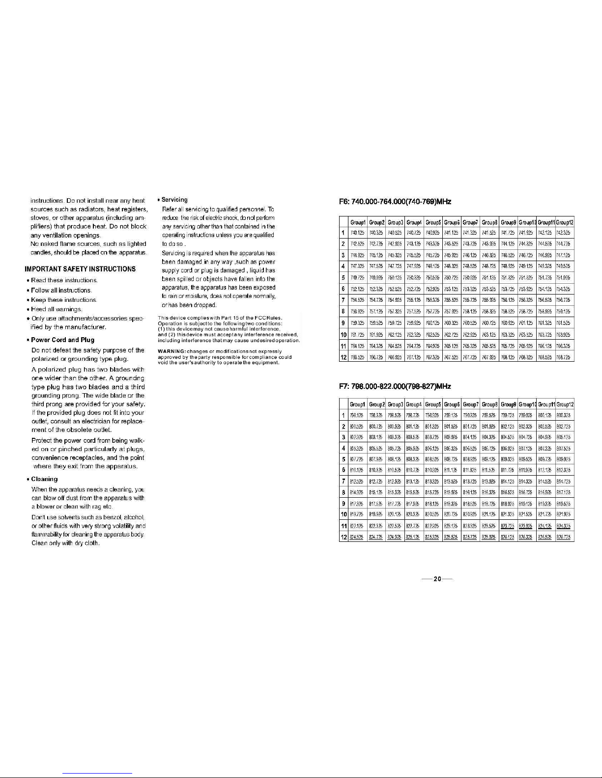

TABLE OF CONTENTS
1. .. . 1
2. ...... ......... . ........... . ....................5
3. .... . .. .... ......... .............5
4. ... .. ... ... . ... . . ....................9
5.
6.
INTRODUCTION
FEATURES
CONTROL ELEMENTS
OPERATION
TECHNICAL SPECIFICATIONS
ANNEX
. ..................................................................................
.... . ..................... ..... ...............
........ . ..... .......................... ..
... .. .. ... ...................... ..... ........ ..........
............................................................15
...................................................................................................17
19
F4: 638.000-662.000(638-664)MHz F4: 638.000-662.000(638-664)MHz
1
Group1 Group2 Group3 Group4 Group5
Group6
638.125 638.325 638.525 638.725 638.925 639.125
639.325 639.525 639.725 639.925 640.125 640.325
640.525 640.725 640.925 641.125 641.325 641.525
641.725 641.925 642.125 642.325 642.525 642.725
642.925 643.125 643.325 643.525 643.725 643.925
644.125 644.325 644.525 644.725 644.925 645.125
645.325 645.525 645.725 645.925 646.125 646.325
646.525 646.725 646.925 647.125 647.325 647.525
647.725 647.925 648.125 648.325 648.525 648.725
648.925 649.125 649.325 649.525 649.725 649.925
650.125 650.325 650.525 650.725 650.925 651.125
651.325 651.525 651.725 651.925 652.125 652.325
2
3
4
5
6
7
8
9
10
11
12
F5: 702.000-726.000(702-731)MHz F5: 702.000-726.000(702-731)MHz
1
2
3
4
5
6
7
8
9
10
11
12
Group1 Group2 Group3 Group4 Group5 Group6 Group7 Group8 Group9 Group10 Group11 Group12
702.125 702.325 702.525 702.725 702.925 703.125 703.325 703.525 703.725 703.925 704.125 704.325
704.525 704.725 704.925 705.125 705.325 705.525 705.725 705.925 706.125 706.325 706.525 706.725
706.925 707.125 707.325 707.525 707.725 707.925 708.125 708.325 708.525 708.725 708.925 709.125
709.325 709.525 709.725 709.925 710.125 710.325 710.525 710.725 710.925 711.125 711.325 711.525
711.725 711.925 712.125 712.325 712.525 712.725 712.925 713.125 713.325 713.525 713.725 713.925
714.125 714.325 714.525 714.725 714.925 715.125 715.325 715.525 715.725 715.925 716.125 716.325
716.525 716.725 716.925 717.125 717.325 717.525 717.725 717.925 718.125 718.325 718.525 718.725
718.925 719.125 719.325 719.525 719.725 719.925 720.125 720.325 720.525 720.725 720.925 721.125
721.325 721.525 721.725 721.925 722.125 722.325 722.525 722.725 722.925 723.125 723.325 723.525
723.725 723.925 724.125 724.325 724.525 724.725 724.925 725.125 725.325 725.525 725.725 725.925
726.125 726.325 726.525 726.725 726.925 727.125 727.325 727.525 727.725 727.925 728.125 728.325
728.525 728.725 728.925 729.125 729.325 729.525 729.725 729.925 730.125 730.325 730.525 730.725
 Loading...