

Show PSA Series, PSA-3600, PSA-3900, PSA-31500 User Manual
R
www.show-pa.com
User's Manual
c
SEIKAKU TECHNICAL GROUP LIMITED
No.1, Lane 17, Sec. 2, Han Shi West Road, Taichung, 401 TAIWAN
Tel:886-4-22313737 Fax:886-4-22346757
http://www.show-pa.com e-mail: sekaku@sekaku.com
All rights reserved to SEIKAKU. All features and content might be changed
without prior notice. Any photocopy, translation, or reproduction of part of this
manual without written permission is forbidden. Copyright 2008 SEIKAKU Group
PROFESSIONAL STEREO AMPLIFIER
PSA Series
Professional Stereo Amplifiers
PSA-3600
PSA-3900
PSA-31500
IMPORTANT!
Please read this manual carefully before operating
this unit for the first time.
All rights reserved to SHOW. All features and content might be changed
without prior notice. Any photocopy, translation, or reproduction of part of
this manual without written permission is forbidden.
-10-
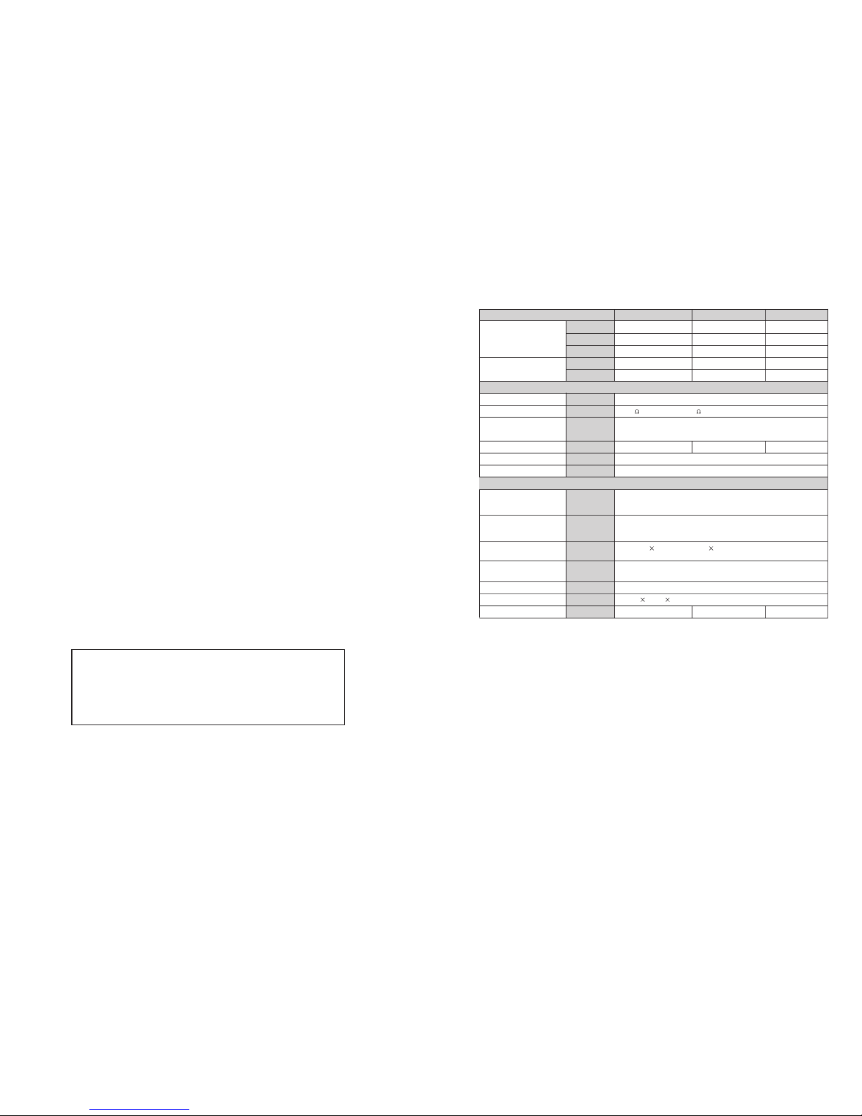
ELECTRICAL SPECIFICATIONS
INPUT SENSITIVITY
INPUT IMPEDANCE
FREQUENCY RESPONSE
(@10dB below rated output
power)
VOLTAGEGAIN
DISTORTION(SMPTE-1M)
S/N Ratio
Full short circuit, open circuit, thermal, ultrasonic, and RF protection
stable into reactive or mismatched loads, turn ON/OFF, muting, tried
crowbar
GENERAL SPECIFICATIONS
PROTECTIONS
1.15 V (+3.4 dBu)
10 K Unbalanced 20 K Balanced
25 Hz~25 KHz +0/-1 dB
-3 dB points: 5 Hz~50 KHz
28 dB
<0.03%
100 dB
32dB 34 dB
4 Ohms (RMS)
4 Ohms (EIAJ)
2 Ohms (EIAJ)
8 Ohms (RMS)
8 Ohms (RMS)
POWER SPECIFICATIONS
750 W 2x
350 W x 2
230 W x 2
710 W
1500 W
PSA-3600
Stereo Mode
(Both channels driven)
20Hz~20KHz
Bridge Mono Mode
20Hz~20kHz
CONTROLS
INDICATORS
CONNECTORS
POWER SUPPLY
DIMENSIONS
WEIGHT
Front: AC switch, Input level control for each channel
Rear: stereo/ parallel/ bridged selector, 30Hz filter selector clip
ON/OFF selector.
INPUT : Active balanced XLR and 1/4"(6.3 mm)TRS
OUTPUT: "Touch-proof" binding posts and speak-on jacks.
Available for 110-120 V or 220~240 VAC, 50/60 Hz
483(W) 460(D) 88.8(H)mm
14.5 kg 17.3 kg 20.7 kg
SIGNAL: 2 green LED CLIP: 2 red LED
POWER: 1 Green LED
1000 W
510 W
285 W
1000 W
2200 W
PSA-3900
1800 W
900 W
560 W
1800 W
3100 W
PSA-31500
9. TECHNICAL SPECIFICATIONS
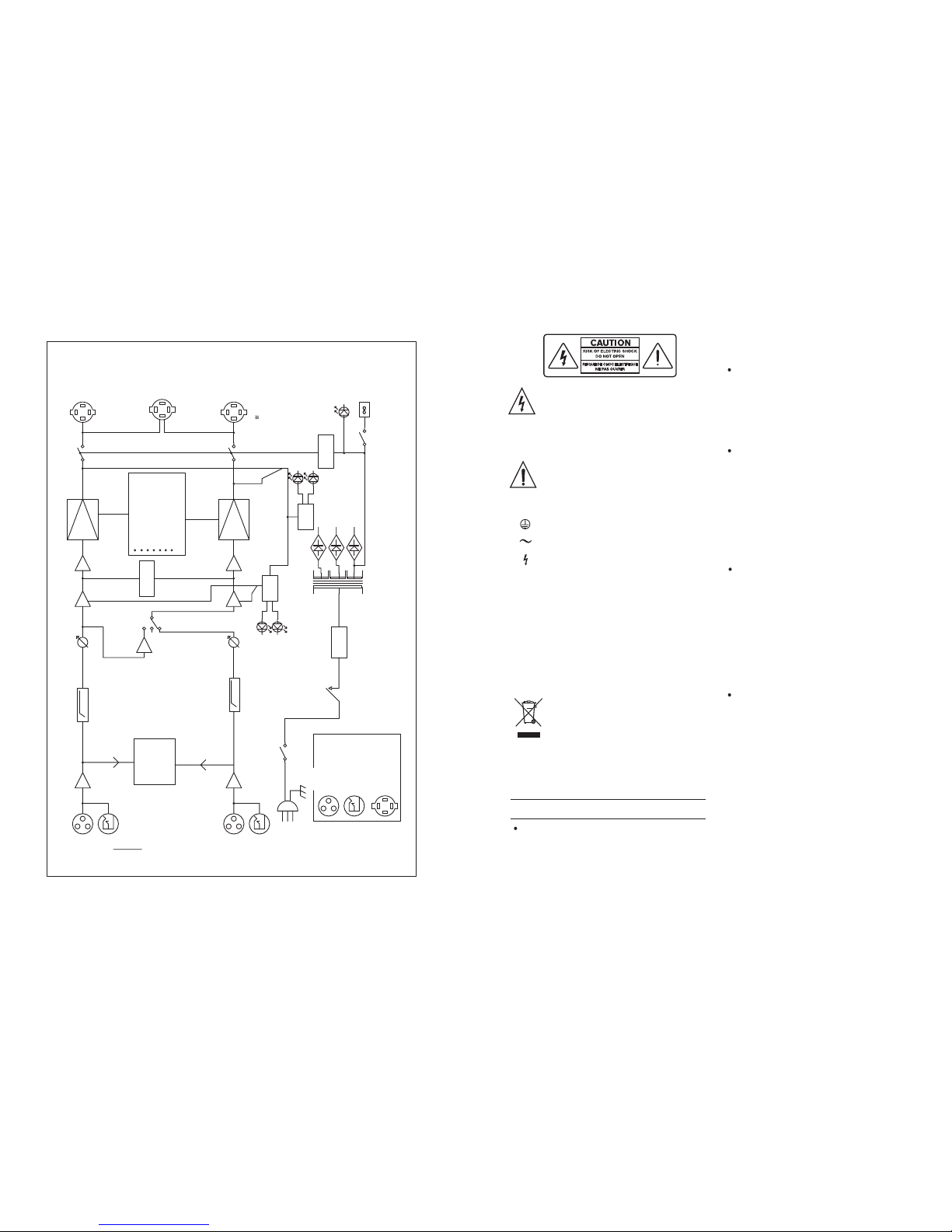
INPUT
LINK
E.R
30Hz-9dB
LA
DIF
PWR
AMP
OUTPUT
CH-A
CH-A
1.15V
RMS
+4dB
15Kohm
BALANCED
SUB WOOFER
(OPTION)
+/-
MODE
INPUT
LINK
E.B
LA
DIF
PWR
AMP
OUTPUT
CH-B
CH-B
AUTORAMP
TURN-ON CIRCUIT SHOCK
DC OFFSET
DC SERVO
OVER TEMP
SHORT
CIRCUIT
CURRENT LIMITER
TURN-ON/TURN-OFF
TRANSIENTS
BRIDGED
PARALLEL
MONO
ACTIVE
CLIP
CH-A
CH-B
AMP
SIG
CH-A
CH-B
OPTION
BINDING POST
TERMINALS
AC PWR
DETECTOR
POWER TRANS
CH-A
CH-B
PROT&PRE
PWR
INDR
2-SPEED
FANS
IN-RUSH
CURRENT
POWER
SWITCH
CIRCUIT
BREAKER
AC POWER
120V/220V/230V
/240V50/60Hz
(OPTION)
:XLR
CONNECTOR
:1/4" PHONE JACK
:SPEAKON
CONNECTOR
NOTICE
30Hz-9dB
8. BLOCK DIAGRAM
-9-
SAFETY RELATED SYMBOLS
The symbol is used to indicate that
some hazardous live terminals are
involved within this apparatus, even
under the normal operating conditions.
The symbol is used in the service
documentation to indicate that specific
component shall be only replaced by
the component specified in that
Documentation for safety reasons.
Protective grounding terminal.
Alternating current /voltage.
ON: Denotes the apparatus turns on.
OFF: Denotes the apparatus turns off,
because of using the single pole switch,
be sure to unplug the AC power to prevent
any electric shock before you proceed your
service.
WARNING: Describes precautions that
should be observed to prevent the danger
of injury or death to the user.
CAUTION: Describes precautions that
should be observed to prevent danger of the
apparatus.
WARNING
Power Supply
Ensure the source voltage matches the
voltage of the power supply before turning
ON the apparatus.
Unplug this apparatus during
lightning storms or when unused for
long periods of time.
External Connection
The external wiring connected to the
output hazardous live terminals requires
installation by an instructed person, or
the use of ready made leads or cords.
Do not Remove any Cover
There are maybe some areas with
high voltages inside, to reduce the risk
of electric shock, do not remove any
cover if the power supply is connected.
The cover should be removed by the
qualified personnel only.
No user serviceable parts inside.
Fuse
To prevent a fire, make sure to use fuses
with specified standard(current,voltage,
type). Do not use a different fuse or short
circuit the fuse holder.
Before replacing the fuse, turn OFF
the apparatus and disconnected the
power source.
Protective Grounding
Never cut off the int ernal or e xternal pr otective grounding wire or disconnect the
wiring of protective grounding terminal.
Hazardous live terminal .
Disposing of this product should
not be placed in municipal waste
and should be separate collection.
Before turning the product ON, make sure
that it is connected to Ground. This is to
prevent the risk of electric shock. Never
cut internal or external Ground wires.
Likewise, never remove Ground wiring
from the Protective Ground Terminal.
The apparatus shall be connected to a
mains socket outlet with a protective
earthing connection.
 Loading...