

Page 1
ACCESSORY
TA0141
Front Ramp Kit
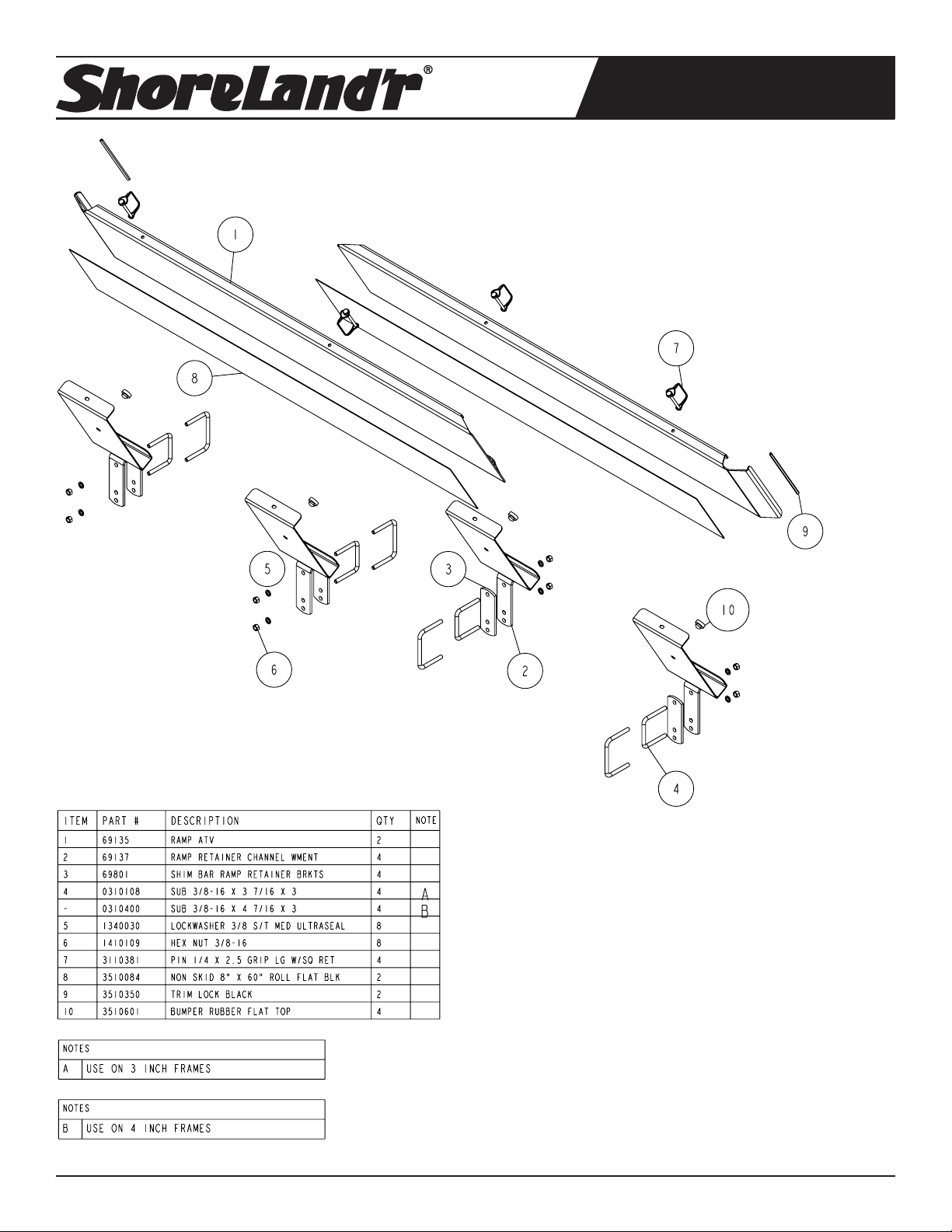
TA0141 Front Ramp Kit
The TA0141 front ramp kit is designed to attach to the front cross
frame tube of the PS5x10, PS5x14, and the PS6x12. It replaces the
TA0091 kit that is currently used on the 2ATV and 3ATV utility trailer
models. The kit includes the ramps and all attaching hardware for
converting the ramps into a front shield while being stored for transport. The ramp retainer channels are designed to accommodate
U-bolts for attaching them to either a 2x3” or 2x4” frame tube.
Installing the ramps in the following manner will allow for the removal of the ramp from the *left side of the trailer rst.
*Left and Right side of trailer is indicated by standing at the
rear of the trailer.
Midwest Industries, Inc. Ida Grove, IA 51445 800.859.3028 www.shorelandr.com 0003892
Page 1 REV B 02/28/08
Page 2
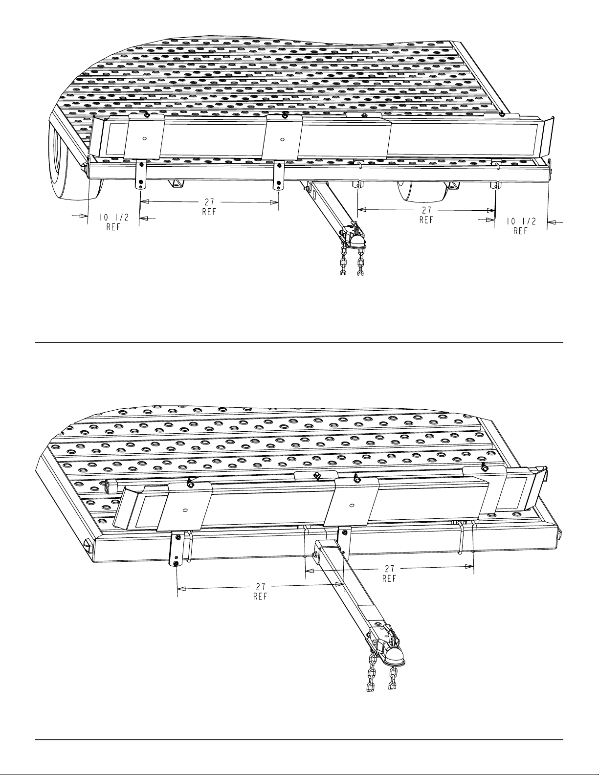
Diagram A
Diagram B
2ATV
3ATV
PS5X10
PS5X14
PS6X12
Midwest Industries, Inc. Ida Grove, IA 51445 800.859.3028 www.shorelandr.com 0003892
Page 2 REV B 02/28/08
Page 3

Removal of Existing Front Stop
Remove the front stop weldment from the front of the utility trailer.
Loosen and remove the 3/8” X 3” U-bolts, 3/8” lock washers, 3/8”
at washers and 3/8” hex nuts. Do Not Discard!
NOTE: The existing front stop weldment can be used as a side
stop/rail option.
Installation Instructions
• Locate the four ramp retainer attachment channels. Note that
they are all identical.
• The two ramp retainer attachment channels on the *right side
of the trailer will be installed on the front side of the trailer front
frame tube so it will support the ramp as shown in the dia grams A and B.
• Note that the kit is supplied with two different size U-bolts. Se lect the proper size to t your frame tube. Place one of the
correct size square U-bolt around the front frame tube so the
legs of the U-bolt are pointing forward. Align the holes in one of
the ramp retainer attachment channels with the U-bolt legs, then
slide into position. Note that this channel is mounted on the
front side of the frame tube. Secure in place with 3/8” lock
washers and 3/8” hex nuts.
• Position the U-bolt so it is 10 ½” from the outside of the side
frame tube as shown on the 2ATV and 3ATV trailers in Dia gram A. Position them so they are as shown in Diagram B for
the PS5x10, PS5x14, and PS4x12 trailers.
• Repeat the mounting process on the second channel. Position
this ramp retainer attachment channel so that the center hole
in the ramp retainer bracket is 27” from the center hole in the
ramp retainer channel just installed. Tighten enough to hold in
position until the ramp is installed for nal spacing.
• Install the remaining two ramp retainer attachment channels
on the left side of the trailer to the rear side of the front frame
tube as shown in Diagrams A and B using the steps above.
Placing them on the rear of the frame tube allows the ramps to
overlap past each other in the middle.
• Once all four of the ramp retainer attachment channels are at-
tached to the frame, position the right ramp into the ramp re tainer attachment channels. The ramp can either be slid into
the end of the channels or else placed in the approximate posi tion, then rotated into place.
wire retainer through the aligned holes in the ramp and the
retainer attachment channel positioned 10 ½” from the side of
the frame and secure.
• Align the hole in the second ramp retainer attachment channel
with the second hole in the ramp. Note that the U-bolt may
have to be loosened so the ramp retainer attaching channel
can be moved either direction to align the holes. When aligned,
insert a second ¼” pin with wire retainer. Once the pin is in-
serted, retighten the U-bolt just loosened to adjust for proper
hole spacing. The two pins will secure the ramps in the trans port position.
• Note the passenger side ramp must always be installed
rst.
• Repeat the above process on the second ramp on the drivers
side of the trailer.
• Installation is complete. The ramps can now be stored secure-
ly during the towing process and can be easily removed for
either loading or unloading the machines.
Using The Ramps
• Always remove the ramp that is on the *left side of the
trailer rst. The ramps are removed from its normal trans-
port position by removing the two ¼” retainer pins that attach
the ramp to the ramp retainer attachment channels.
• Once the pins are removed, rotate the ramp backward on top
to remove it from the ramp retainer attachment channels.
• Place the hook end of the ramp over the side frame tube or
the rear tube of the trailer deck so the hook end catches over
the inside top of the tube. This will secure it in place while load ing the machine.
• Repeat the above process on the second ramp. Space the
ramps to mate the wheel centers of the machine.
• Once the machines are loaded and the ramps are ready for
storage, place them in the ramp retainer attachment channels
using a reverse process of removing them.
NOTE: The TA0141 replaces the TA0091. Please contact
customer service if more information is required.
*Left and Right side of trailer is indicated by standing at the
rear of the trailer.
• See Diagram A. Align the holes provided in the edge of the
ramp with the holes in the center of the ramp retainer attach ment channels as follows: Place one of the ¼” pins with the
Midwest Industries, Inc. Ida Grove, IA 51445 800.859.3028 www.shorelandr.com 0003892
Page 3 REV B 02/28/08
Page 4

Midwest Industries, Inc. Ida Grove, IA 51445 800.859.3028 www.shorelandr.com 0003892
Page 4 REV B 02/28/08
 Loading...