

Page 1
®
Titan BrakeRite
Electric Over Hydraulic Brake Kits
BRAKE KIT TRAILER SIZE TRAILER MODELS
TA0016 Under 6,000 lbs. GVWR 3,000, 4,000 & 4600 lb. Aluminum
3,000, 4,000, & 4600 lb. Steel
Reservoir Caps
Diagram A
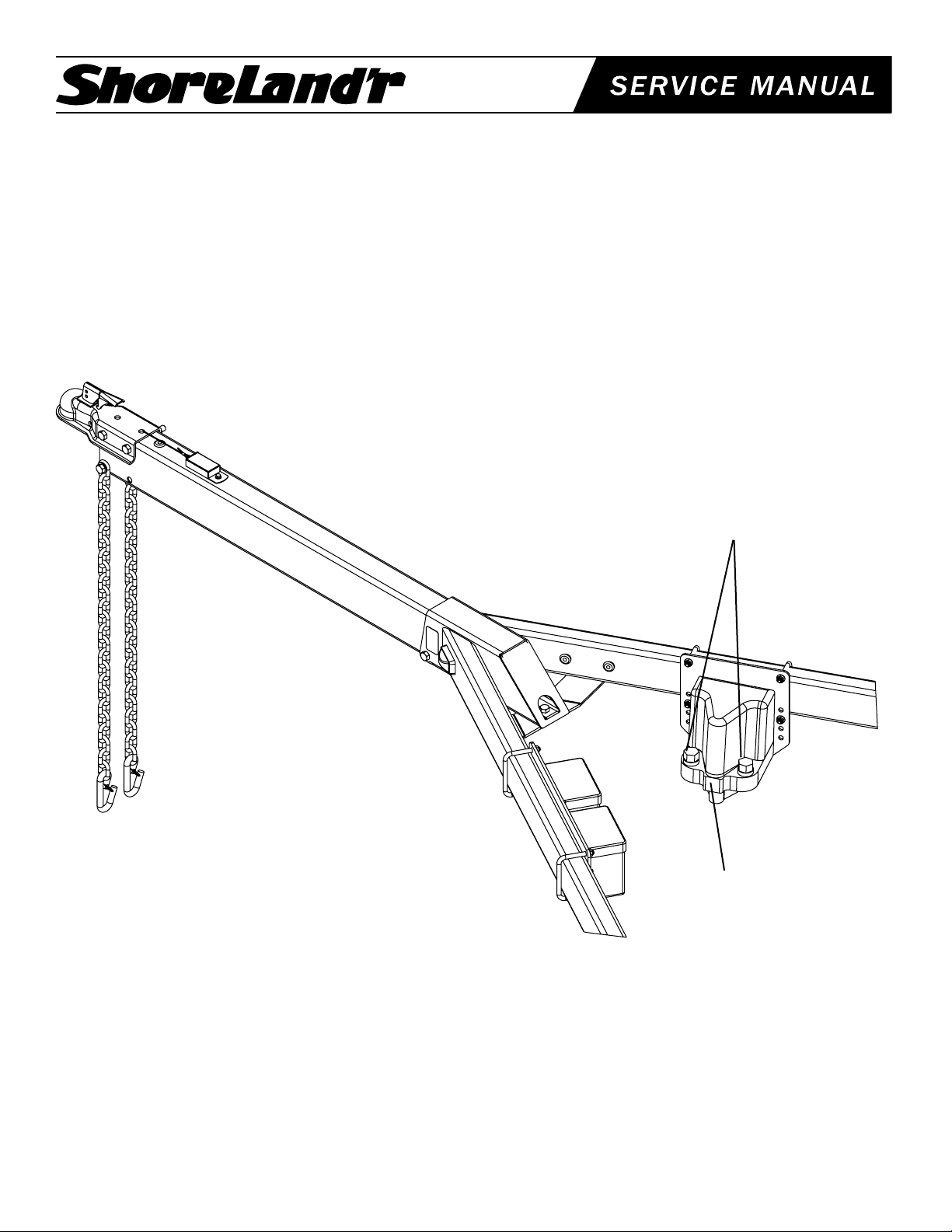
The electric over hydraulic brake system is designed to replace the
hydraulic surge brake actuator that was shipped on your trailer as
standard equipment. The electric over hydraulic system is activated electrically when you apply the brakes on the tow vehicle. It can
also be operated by a manual cab control inside the tow vehicle
that allows the operator to apply the brakes on the trailer without
applying the brakes on the tow vehicle.
The kit is designed to adapt to different size trailer frames in
Brakeline Port
both steel and aluminum trailer construction. You will have
extra parts and fasteners above what is required for your
particular application.
The following instructions are written to address the different installations and will refer to the various diagrams for clarity. Note that
the view shown may not necessarily be an exact view of your trailer
but the instructions will direct you to how to change your existing
trailer brake system to the electric over hydraulic system.
Midwest Industries, Inc. Ida Grove, IA 51445 800.859.3028 www.shorelandr.com 0003264
Page 1
REV B 12/06/04
Page 2
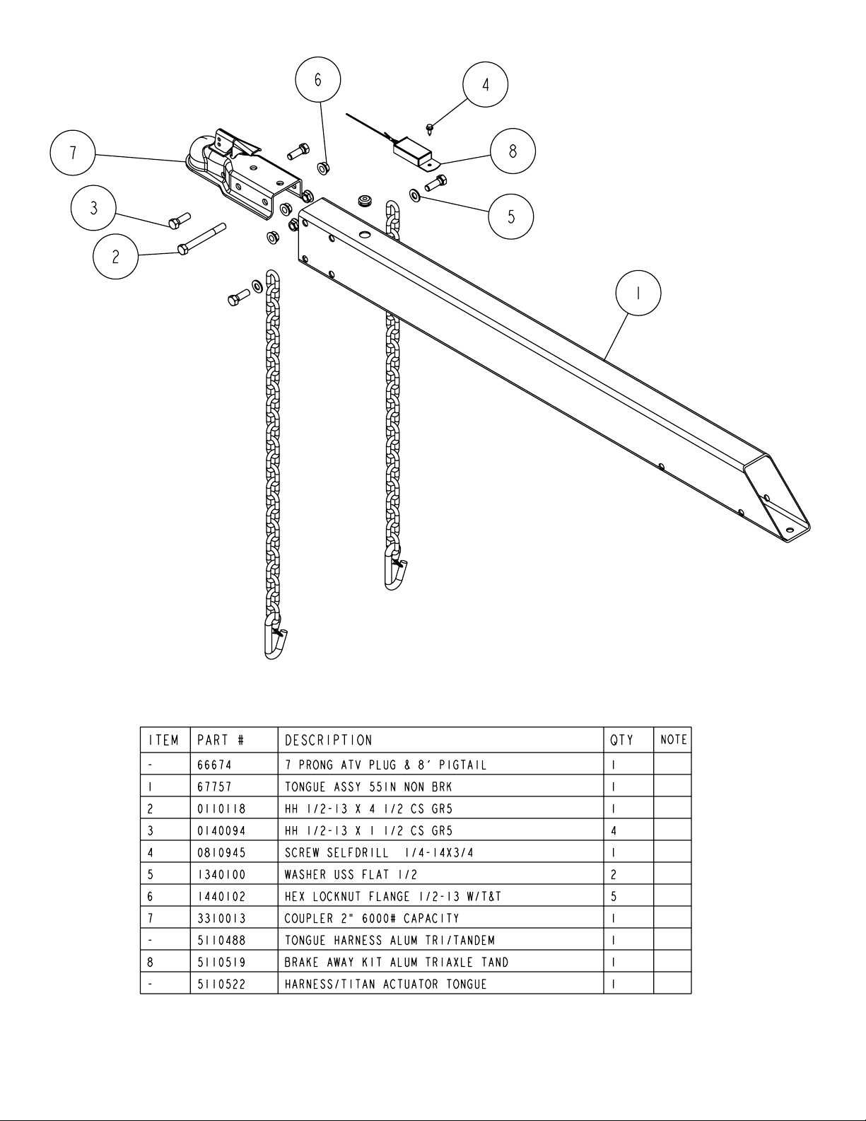
Diagram C
Midwest Industries, Inc. Ida Grove, IA 51445 800.859.3028 www.shorelandr.com 0003264
Page 2
REV B 12/06/04
Page 3
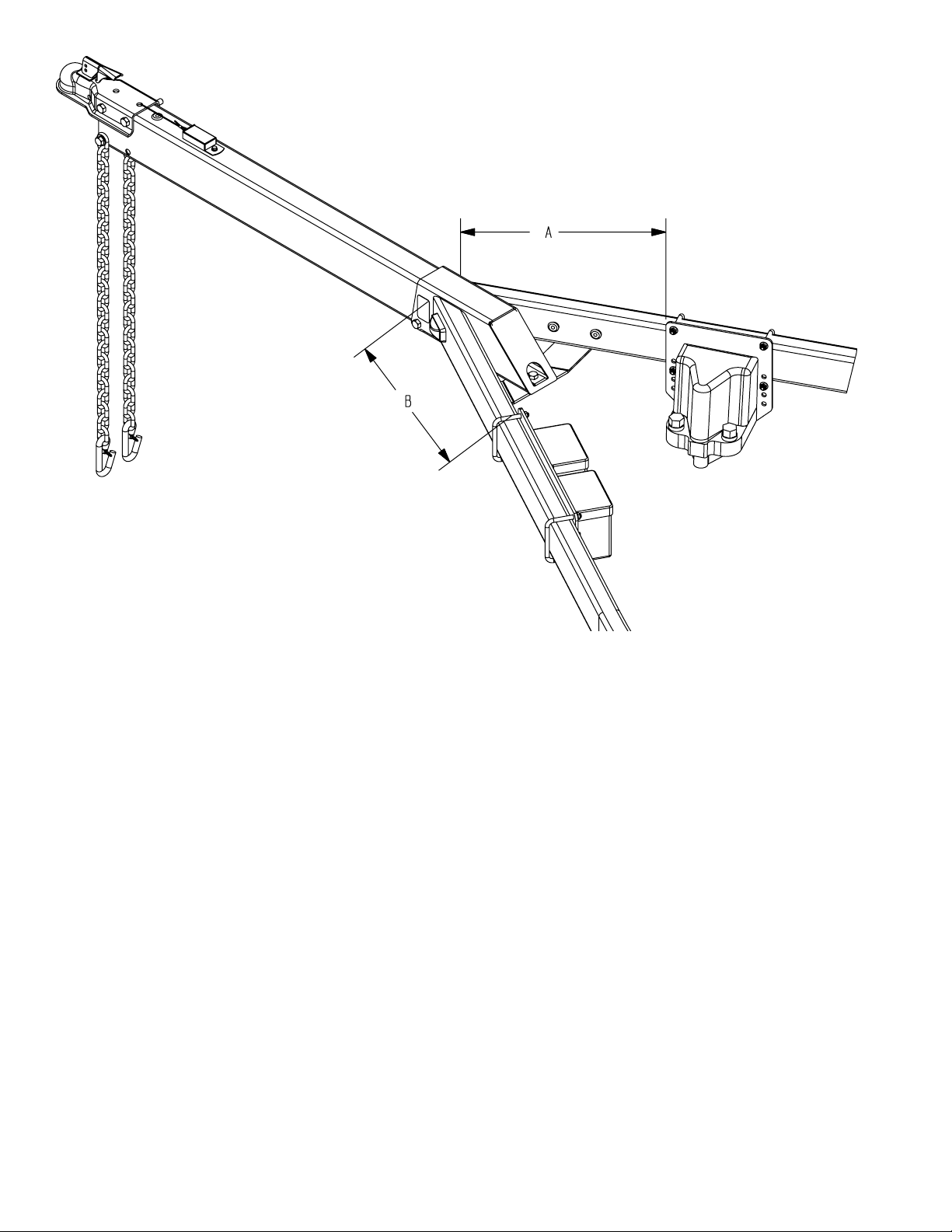
Diagram AA
Installation Instructions
Diagram A is a typical view of how the new electric over hydraulic system will be installed on your trailer. Diagram A is a generic
view of a steel and aluminum frame trailer coupler under 6,000#
GVWR.
Remove all items and hardware from the box and sort by size.
Installation Instructions for Aluminum Frame
Trailers with a GVWR (Gross Vehicle Weight
Rating) Less than 6,000 lb.
Use Kit No. TA0016
Removing the existing actuator from the tongue.
1. Unthread the tongue brake line fitting from the coupling connecting it to the frame brake line tubing.
2. Loosen the rear tongue bolt attaching the tongue and tongue
cover to the frame. This will allow you to move the tongue cover
while installing the new wire harnesses into the tongue. NOTE:
ALL NEW WIRES USED IN THE INSTALLATION WILL HAVE TO
BE PLACED THROUGH THE HOLE IN THE TONGUE COVER.
3. Remove the bolts attaching the existing actuator to the tongue.
The complete unit can be now be removed pulling the tongue brake
line tubing out of the front of the tongue.
4. Remove the safety chains from the tongue. The new safety
chains supplied in the kit will be installed.
4. Unplug the tongue wire harness from the frame harness using
the plug-in connectors. It will not be used in the new installation.
IMPORTANT
Note: The bolts in the kit used to attach the coupler and safety
chains on all trailers are stainless steel. Also the U-bolts for
attaching the mounting brackets for the actuator and the battery boxes on the aluminum trailers are stainless steel. They
require that you use the appropriate size nuts with the nylon
inserts. It is also recommended that you use an anti-seize lubricant (Supplied in the kit) on the threads before the nuts are
installed to prevent seizing when they are tightened. All other
U-bolts in the kit are plated steel and are used on the steel
frame trailers. The standard flange lock nuts are used on these
U-bolts.) Failure to mate the proper nuts with proper U-bolts
will cause the nuts to freeze when tightening thus preventing
the U-bolts from tightening properly.
Midwest Industries, Inc. Ida Grove, IA 51445 800.859.3028 www.shorelandr.com 0003264
Page 3
REV B 12/06/04
Page 4

Diagram E
Midwest Industries, Inc. Ida Grove, IA 51445 800.859.3028 www.shorelandr.com 0003264
Page 4
REV B 12/06/04
Page 5

Installing The New Coupler Assembly
1. Locate the new 2” coupler in the hardware box, Item No. 7 in
Diagram C. Note that this coupler must be used because it has a
6,000 lb. capacity rating which is greater than the standard Class II
or Class III couplers.
2. Place it on the tongue and attach using a 1/2” x 4” hex bolt (Item
No. 2) through the holes in the back of the coupler. Secure with a
1/2” lock nut.
brake line fitting into the port on the actuator shown in Diagram A.
Tighten.
Battery Box Installation
1. (See Diagram E) Locate the battery box mounting plate, Item
No. 1 and the battery boxes, Item No. 9. Note that there are two
battery boxes and two batteries. They are both required to power
the brake system in the event of an unwanted disconnect from the
tow vehicle.
3. Attach the front of the coupler to the tongue using two- 1/2” x 11/2” hex bolts (Item No. 3) and lock nuts. Tighten.
Attach the new safety chains provided by placing a 1/2” flat washer on a 1/2” x 1-1/2” hex bolt. Insert the bolt through the end link
on one of the new safety chains provided. Insert the bolt into the
mounting hole that the old chains were removed from. Secure with
the 1/2” flange lock nut. Tighten. Repeat on the other chain.
The breakaway switch shown in the diagram will be installed at a
later time. Instructions for mounting the breakaway switch follow
later in the assembly.
Electric Over Hydraulic Actuator Installation
1. See Diagram E on page 4. Locate the actuator mounting plate,
Item No. 2 and the brake actuator, Item No. 10. Place one each
5/16” lock washer on the three 5/16” x 1” hex bolts. Attach the brake
actuator to the mounting plate using the three 5/16” x 1” hex bolts.
Tighten.
2. Place the assembly on the inside of the side frame. Note that the
mounting plate has the appropriate holes for attaching to 2 x 4”,
and 2 x 5” steel side frame tubing as well as the aluminum I-beams.
See the note at the bottom of the Bill of Materials listed for Diagram
E. Secure the U-bolts to the assembly using the 3/8” flange lock
nuts provided. DO NOT USE THE 3/8” NUTS WITH THE NYLON
INSERTS IN THEM BECAUSE THEY WILL GAULD UP AND YOU
WILL NOT BE ABLE TO TIGHTEN PROPERLY.
3. Place the proper U-bolts over the side frame as shown in Diagram A, insert through the mounting plate and secure with 3/8”
flange lock nuts. Position the mounting bracket on the frame so that
the front of the bracket is 32 inches from the front of the side frame.
See Dimension A in Diagram AA. Tighten.
4. Once the actuator is located attach the grounding ring on the
actuator white wire lead to the inside of the mounting plate with a
No. 10 self-tapping screw so continuity can be achieved through
the paint coating.
Brake Line Tubing Connection
1. Starting at the front of the trailer, carefully remove the frame
brake line tubing from the black plastic tubing that is mounted in the
side frame used for routing the wiring and the brake line tubing. Remove the tubing so there is sufficient tubing to be routed from the
black plastic tubing to the brake line port as shown on Diagram A.
2. Carefully bend the tubing with smooth round curves making sure
that the line is not kinked as it is formed to its new location.
3. Remove the coupling from the end of the frame brake line used
to connect it to the tongue brake line tubing. Thread the frame
2. Open the battery boxes and remove both the white and violet
wire harness that is shipped in one box. Also remove the breakaway switch that is shipped in the other box. Installation instructions for these items will be addressed at a later time.
3. Attach the two battery boxes to the mounting plate using 1/4” x 1”
carriage bolts and 1/4” lock nuts as shown in Diagram E. Attach the
white ground wire just removed to the negative terminals (marked
with black plastic cap) of the two batteries. Route the wires from
one battery box to the other using the notch located in the back
side of the battery box. Route the end of the wire harness with the
round grounding lead out the notch of the second box. Place the
grounding ring on one of the bolts being used to attach the battery
boxes to the mounting plate. This is necessary so that a positive
ground is created for the system to function properly. Once all bolts
are installed, tighten.
4. Place the battery box assembly on the inside of the I-beam as
shown and secure to the I-beam using two of the proper size Ubolts to fit the I-beam. Place the U-bolts over the I-beam as shown
in Diagram AA and secure with 3/8” nuts with the nylon inserts. Position the battery box on the I-beam. The front edge of the mounting
bracket should be located back a minimum of 12” from the front of
the I-beam (Dimension B on Diagram AA). Tighten. This distance
is necessary to allow the winch post to be adjusted backwards on
the tongue.
Breakaway Switch Installation
The breakaway switch provided is required so that the brakes on
the trailer will be applied in the event of an unwanted disconnect
from the tow vehicle.
1. Locate the breakaway switch, Item No. 8 in Diagram C. It was
shipped in one of the battery boxes along with a battery. Place it on
the topside of the tongue located just behind the coupler as shown
in Diagram C. It must be positioned so that the front of the breakaway switch is three (3) inches behind the coupler installed earlier.
This is necessary so that the pin in the switch can be pulled out the
front of the breakaway switch to automatically activate the brakes
in an emergency. Mark the mounting hole location. Drill a 13/64”
pilot hole in this location. Replace the breakaway switch. Insert the
1/4” self-tapping screw provided and secure in place.
2. Locate the violet wire harness that was shipped with the white
grounding harness and removed from the other battery box. Attach
it to the positive terminals of both batteries (Marked with the red
plastic caps). Route the violet wire from one battery to the other
through the notches provided in the backside of each battery box.
3. The remaining terminal on the violet wire as well as the brown
wires from the breakaway switch will be connected to wire harness
No. 5110522 at a later time.
Midwest Industries, Inc. Ida Grove, IA 51445 800.859.3028 www.shorelandr.com 0003264
Page 5
REV B 12/06/04
Page 6

Wiring Instructions
The wire harnesses for all kits are made identical. Some installations will have excess wire. All excess wire can be placed back into
the tongue when assembly is complete.
Diagram G is a wiring diagram showing what colors wires are connected together for the brake system to operate properly.
Each wire harness section is identified by number as indicated on
the schematic drawing Diagram G.
1. Locate wire harness No. 5110488. This harness is used to attach the 7-prong tongue harness to the lights on the trailer. Insert
the wire harness into the front of the tongue. Pull it through the
tongue and out the rear through the hole provided in the tongue
cover. Connect the harness to the wire harnesses in the trailer side
frames. Note that the two- single brown wire leads will not be used
in this application. The connector plugs on these two single brown
wires must be taped and then placed inside the tongue. See Diagram G. Leave the front of the wire harness No. 5110488 out the
front of the tongue until directed later.
2. Locate wire harness No. 5110522. Note that one end of the
harness has a violet and brown wire connected at a female plug.
The individual wires in this harness are taped together at various
locations. Cut the tape attaching the violet and brown wire that are
joined at the female plug the same distance as what the brown wire
is long. (Approximately 30”).
3. Attach the violet wire from the positive side of the battery to the
plug attaching the violet and brown wires in harness No. 5110522
just described.
to the frame with the brake line clips provided in the kit to keep them
attached to the aluminum frame. Note that the harness No.
5110522 harness is a universal harness that has plug connectors
on it. These plugs are to be cut off and the wire cut to the required
length to attach them to the leads from the actuator. Cut, strip the
coating on the wires approximately 5/16” and mate the ends of
harness No. 5110522 to the actuator wires as shown in Diagram G.
Attach them together with the butt connectors that are already attached to the leads on the actuator. Tape all connections just made
with electrical tape.
10. Once all connections are made, push any excess wires into
either the tongue or the side frame of the trailer. Place in the rubber
grommets either removed or supplied in the kit to protect the wires
from fraying when the trailer is towed.
11. Wiring should now be complete. Retighten the rear bolt that attaches the tongue cover and holds the tongue into the frame that
was loosened earlier to assist in the installation of the wires.
----------------------------------------------------------------------------------------
----------------------------------------------------------------------------------------
Installation Instructions for Steel Trailers with a
GVWR (Gross Vehicle Weight Rating) Less than
6,000 lb.
Use Kit No. TA0016
Removing the existing actuator from the tongue.
1. Unthread the tongue brake line fitting from the coupling connecting it to the frame brake line tubing.
4. Pull this brown wire, and the remaining single bullet plugs, black,
blue, and another brown wire through the hole in the tongue cover
in the back of the tongue and out the front of the tongue. The end
of the harness that has the double plugs must be to the rear of the
tongue when properly installed and will be connected to the actuator at a later time.
5. Route the two brown wires from the breakaway down through
the hole in the top of the tongue and out the front of the tongue.
Connect the two- single brown wires of harness No. 5110522 to
the wires from the breakaway switch. Note that either wire from
the breakaway switch can be plugged into either brown wire in the
harness. The remaining black and blue wires will be attached to the
tongue harness at a later time.
6. Locate the tongue harness with the 7-prong plug supplied in the
kit. Insert the end opposite of the 7-prong wire harness into the hole
in the top of the tongue that the original wire harness was removed
from. Pull the wire harness out of the front of the tongue so they
can be connected to the other harnesses.
7. Connect the wires in the 7-prong tongue harness with the wires
in harness No. 5110488 and 5110522 just installed. Mate the correct color wires as shown in Diagram G.
8. Route the white ground wire to the side of the tongue. Secure
the grounding ring on the wire to the tongue with a No, 10 self-tapping screw.
9. Route the remaining wire harness No. 5110522 down the side frame
of the trailer to the actuator. Note that the kit has split plastic conduit
and plastic ties to hold and secure the wires. The wires can be attached
2. Loosen the rear tongue bolt attaching the tongue and tongue
cover to the frame. This will allow you to move the tongue cover
while installing the new wire harnesses into the tongue. NOTE:
ALL NEW WIRES USED IN THE INSTALLATION WILL HAVE TO
BE PLACED THROUGH THE HOLE IN THE TONGUE COVER.
3. Remove the bolts attaching the existing actuator to the tongue.
The complete unit can be now be removed pulling the tongue brake
line tubing out of the front of the tongue.
4. Remove the safety chains from the tongue. The new safety
chains supplied in the kit will be installed.
5. Unplug the tongue wire harness from the frame harness using
the plug-in connectors. It will not be used in the new installation.
IMPORTANT
Note: The bolts in the kit used to attach the coupler and safety
chains on all trailers are stainless steel. Also the U-bolts for
attaching the mounting brackets for the actuator and the battery boxes on the aluminum trailers are stainless steel. They
require that you use the appropriate size nuts with the nylon
inserts. It is also recommended that you use an anti-seize lubricant (Supplied in the kit) on the threads before the nuts are
installed to prevent seizing when they are tightened. All other
U-bolts in the kit are plated steel and are used on the steel
frame trailers. The standard flange lock nuts are used on these
U-bolts.) Failure to mate the proper nuts with proper U-bolts
will cause the nuts to freeze when tightening thus preventing
the U-bolts from tightening properly.
Midwest Industries, Inc. Ida Grove, IA 51445 800.859.3028 www.shorelandr.com 0003264
Page 6
REV B 12/06/04
Page 7

Installing the New Coupler Assembly
1. Locate the new 2” coupler in the hardware box, Item No. 7 in
Diagram C. Note that this coupler must be used because it has a
6,000 lb. capacity rating which is greater than the standard Class II
or Class III couplers.
2. Place it on the tongue and attach using a 1/2” x 4” hex bolt (Item
No. 2) through the holes in the back of the coupler. Secure with a
1/2” lock nut.
3. Attach the front of the coupler to the tongue using two- 1/2” x 11/2” hex bolts (Item No. 3) and lock nuts. Tighten.
Attach the new safety chains provided by placing a 1/2” flat washer on a 1/2” x 1-1/2” hex bolt. Insert the bolt through the end link
on one of the new safety chains provided. Insert the bolt into the
mounting hole that the old chains were removed from. Secure with
the 1/2” flange lock nut. Tighten. Repeat on the other chain.
3. Carefully bend and route the tubing backward, down the inside
of the side frame towards the actuator just installed. Care should be
used in forming the line so that it does not kink.
4. Route the brake line over to the port on the actuator as identified
in Diagram A. Coil any excess line you may have into a 3” diameter coil to use up the excess. Tighten the brake line fitting into the
actuator.
5. Locate the brake line tubing clips and No. 10 self-tapping screws
provided. Place the tubing clip over the brake line while pressing
the brake line tubing up against the center inside of the trailer side
frame. Place a self-tapping screw into the hole in the tubing clip and
drill the self-tapping screw into the side frame of the trailer. Repeat
on the other clips.
Battery Box Installation
Steel Frame Installation
The breakaway switch shown in the diagram will be installed at a
later time. Instructions for mounting the breakaway switch follow
later in the assembly.
Electric Over Hydraulic Actuator Installation
1. See Diagram E. Locate the actuator mounting plate, Item No.
2 and the brake actuator, Item No. 10. Place one each 5/16” lock
washer on the three 5/16” x 1” hex bolts. Attach the brake actuator
to the mounting plate using the three 5/16” x 1” hex bolts. Tighten.
2. Place the assembly on the inside of the side frame. Note that the
mounting plate has the appropriate holes for attaching to 2 x 4”,
and 2 x 5” steel side frame tubing as well as the aluminum I-beams.
Use the 3/8” x 4 7/16” x 3” U-bolts for a 2” x 4” frame or the 3/8” x
5 7/16” x 3” U-bolts for the 2” x 5” side frame to mount the actuator
assembly to the side frame. See the note at the bottom of the Bill of
Materials listed for Diagram E. Secure the U-bolts to the assembly
using the 3/8” flange lock nuts provided. DO NOT USE THE 3/8”
NUTS WITH THE NYLON INSERTS IN THEM BECAUSE THEY
WILL GAULD UP AND YOU WILL NOT BE ABLE TO TIGHTEN
PROPERLY.
3. Place the proper U-bolts over the side frame as shown in Diagram A, insert through the mounting plate and secure with 3/8”
flange lock nuts. Position the mounting bracket on the frame so that
the front of the bracket is 32 inches from the front of the side frame.
(See Dimension A in Diagram A) Tighten.
4. Once the actuator is located attach the grounding ring on the
actuator white wire lead to the inside of the frame with a No. 10
self-tapping screw so continuity can be achieved through the paint
coating.
Brake Line Tubing Connection
1. Note that the frame brake line tubing in the steel frame exits
through a fixed hole position in the side frame. It needs to be routed
backwards to the new actuator location.
2. Locate the coiled length of brake line tubing supplied in the kit.
Uncoil the line and attach one end to the frame brake line using the
coupler that was used to connect the tongue brake line tubing to
the side frame tubing. Tighten.
1. (See Diagram E) Locate the battery box mounting plate, Item
No. 1 and the battery boxes, Item No. 9. Note that there are two
battery boxes and two batteries. They are both required to power
the brake system in the event of an unwanted disconnect from the
tow vehicle.
2. Open the battery boxes and remove both the white and violet
wire harnesses that are shipped in one box. Also remove the breakaway switch that is shipped in the other box. Installation instructions for these items will be addressed at a later time.
3. Attach the two battery boxes to the mounting plate using 1/4” x
1” carriage bolts and 1/4” lock nuts as shown in Diagram E. Once
all bolts are installed, tighten.
4. Place the assembly on the inside of the frame as shown in Diagram A and secure to the frame using two of the appropriate size
U-bolts as described earlier in the actuator assembly instructions.
Secure with 3/8” flange lock nuts. Position the battery box assembly so it is 21 inches from the front of the frame to the front of the
mounting bracket as shown in Diagram AA, Dimension B. Tighten.
5. Attach the white ground wire just removed to the negative terminals (marked with black plastic cap) of the two batteries. Route the
wire from one battery box to the other using the notch located in
the back side of the battery box.. Route the end of the wire harness
with the round grounding lead out the notch of the second box. Position it on the inside of the trailer side frame and attach with a No.
10 self-tapping screw. This is necessary so that a positive ground
is created for the system to function properly.
Breakaway Switch Installation
The breakaway switch provided is required so that the brakes on
the trailer will be applied in the event of an unwanted disconnect
from the tow vehicle.
1. Locate the breakaway switch, Item No. 8 in Diagram C. It was
shipped in one of the battery boxes along with a battery. Place it on
the topside of the tongue located just behind the coupler as shown
in Diagram C. It must be positioned so that the front of the breakaway switch is three (3) inches behind the coupler installed earlier.
This is necessary so that the pin in the switch can be pulled out the
front of the breakaway switch to automatically activate the brakes
Midwest Industries, Inc. Ida Grove, IA 51445 800.859.3028 www.shorelandr.com 0003264
Page 7
REV B 12/06/04
Page 8
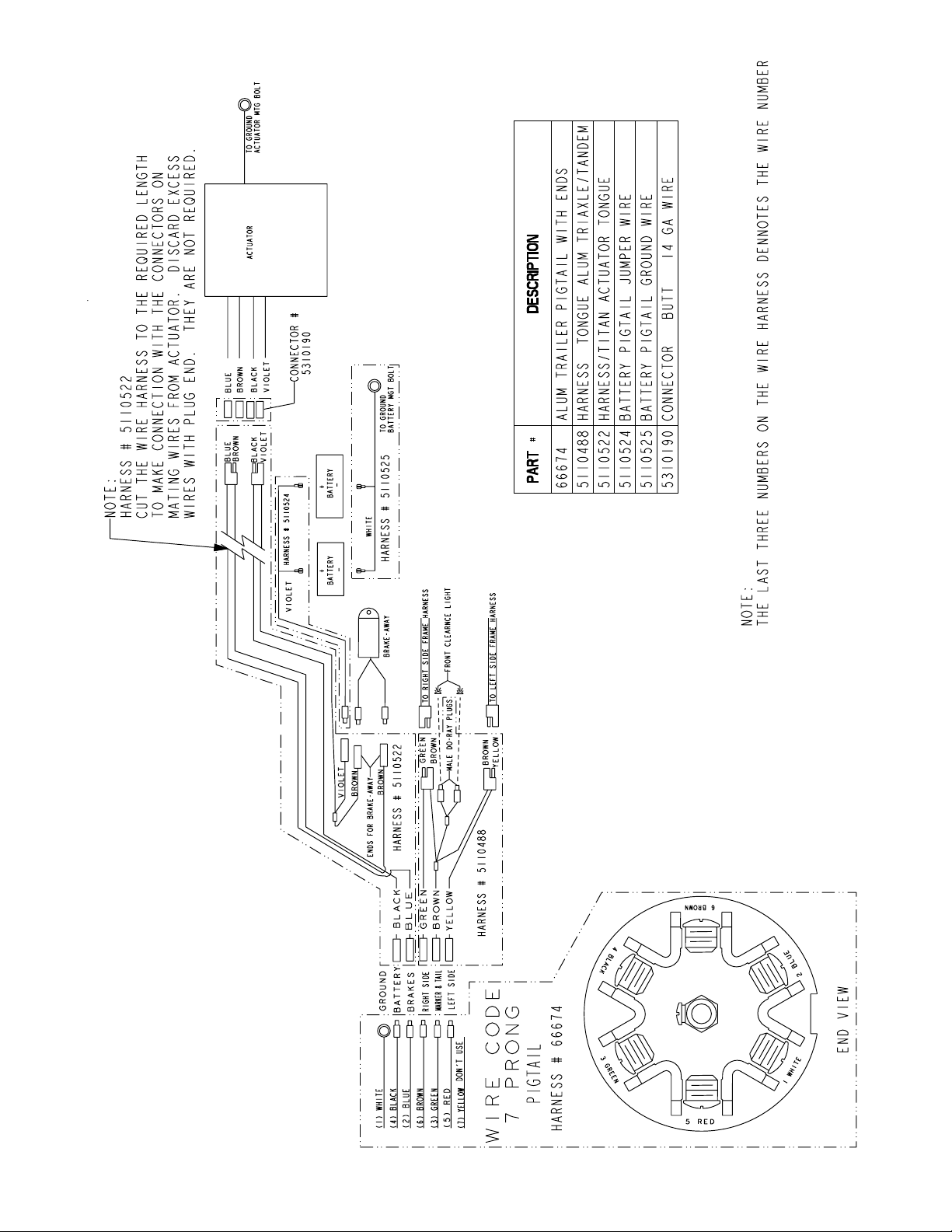
Diagram G
Midwest Industries, Inc. Ida Grove, IA 51445 800.859.3028 www.shorelandr.com 0003264
Page 8
REV B 12/06/04
Page 9

in an emergency. Mark the mounting hole location. Drill a 13/64”
pilot hole in this location. Replace the breakaway switch. Insert the
1/4” self-tapping screw provided and secure in place.
2. Locate the violet wire harness that was shipped with the white
grounding harness and removed from the other battery box. Attach
it to the positive terminals of both batteries (Marked with the red
plastic caps). Route the violet wire from one battery to the other
through the notches provided in the backside of each battery box.
can be connected to the other harnesses.
6. Connect the wires in the 7-prong tongue harness with the wires
in harness No. 5110488 and 5110522 just installed. Mate the correct color wires as shown in Diagram G.
7. Route the white ground wire to the side of the tongue. Secure
the grounding ring on the wire to the tongue with a No, 10 self-tapping screw.
3. The remaining terminal on the violet wire as well as the brown
wires from the breakaway switch will be connected to wire harness
No. 5110522 at a later time.
Wiring Instructions
The wire harnesses for all kits are made identical. Some installations will have excess wire. All excess wire can be placed back into
the tongue when assembly is complete.
Diagram G is a wiring diagram showing what colors wires are connected together for the brake system to operate properly.
Each wire harness section is identified by number as indicated on
the schematic drawing Diagram G.
1. Locate wire harness No. 5110488. This harness is used to attach the 7-prong tongue harness to the lights on the trailer. Insert
the wire harness into the front of the tongue. Pull it through the
tongue and out the rear through the hole provided in the tongue
cover. Connect the harness to the wire harnesses in the trailer side
frames. Note that the two- single brown wire leads will not be used
in this application. The connector plugs on these two single brown
wires must be taped and then placed inside the tongue. See Diagram G. Leave the front of the wire harness No. 5110488 out the
front of the tongue until directed later.
8. Route the remaining wire harness No. 5110522 down the side frame
of the trailer to the actuator. Note that the kit has split lastic conduit
and plastic ties to hold and secure the wires. The wires can be taped
or tied to the brake line to help support them on a steel frame trailer.
Note that the harness No. 5110522 harness is a universal harness
that has plug connectors on it. These plugs are to be cut off and the
wires cut to the required length to attach them to the leads from the
actuator. Cut, strip the coating on the wires approximately 5/16”
and mate the ends of harness No. 5110522 to the actuator wires
as shown in Diagram G. Attach them together with the butt connectors that are already attached to the leads on the actuator. Tape all
connections just made with electrical tape.
9. Once all connections are made, push any excess wires into either the tongue or the side frame of the trailer. Place in the rubber
grommets either removed or supplied in the kit to protect the wires
from fraying when the trailer is towed.
10. Wiring should now be complete. Retighten the rear bolt that
attaches the tongue cover and holds the tongue into the frame that
was loosened earlier to assist in the installation of the wires.
ALL MODELS
Filling the System With Brake Fluid
All Kits
2. Locate wire harness No. 5110522. Note that one end of the
harness has a violet and brown wire connected at a female plug.
The individual wires in this harness are taped together at various
locations. Cut the tape attaching the violet and brown wire that are
joined at the female plug the same distance as what the brown wire
is long. (Approximately 30”).
3. Attach the violet wire from the positive side of the battery to the
plug attaching the violet and brown wires in harness No. 5110522
just described.
4. Pull this brown wire, and the remaining single bullet plugs, black,
blue, and another brown wire through the hole in the tongue cover
and out the front of the tongue. The end of the harness that has
the double plugs must be to the rear of the tongue when properly
installed and will be connected to the actuator at a later time.
5. Route the two brown wires from the breakaway down through
the hole in the top of the tongue and out the front of the tongue.
Connect the two- single brown wires of harness No. 5110522 to
the wires from the breakaway switch. Note that either wire from
the breakaway switch can be plugged into either brown wire in the
harness. The remaining black and blue wires will be attached to the
tongue harness at a later time.
6. Locate the tongue harness with the 7-prong plug supplied in the
kit. Insert the end opposite of the 7-prong wire harness into the hole
in the top of the tongue that the original wire harness was removed
from. Pull the wire harness out of the front of the tongue so they
Fill the reservoir on the actuator with an Arctic-SAEJ1702 or
SAEJ1703 brake fluid or a fluid that is comparable. Remove one
of the reservoir caps located on the actuator unit as identified in
Diagram A or B. Only one cap has to be removed. Add fluid until the
reservoir is full. Bleed the brake system following the procedure for
bleeding the brakes. If complete bleeding of the system is required,
it may be necessary to add fluid to the reservoir during the bleeding process. Once the system is completely bled, refill the reservoir
until full. Replace the cap and tighten to seal our any moisture that
may enter during normal use.
Bleeding The Brake System
All Kits
Partial Bleeding of the Hydraulic Brake System
If the electric over hydraulic system is being added to a current
brake system that is already installed and has been in use it is possible that you only need to bleed the air out of the system where
the connections were made in the lines to connect the new actuator
system. The procedure is as follows:
1. Check to make sure brake fluid has been added to the system
as recommended above.
2. Pull the cable on the breakaway switch installed just behind the
coupler. This will pull a pin out the switch automatically activating
the switch. The actuator will now draw its power from the batteries
installed on the trailer. The actuator will continue to run until the bat-
Midwest Industries, Inc. Ida Grove, IA 51445 800.859.3028 www.shorelandr.com 0003264
Page 9
REV B 12/06/04
Page 10

teries are drained. You will be able to hear the actuator motor run.
3. With the actuator running, loosen the bleeder screw on the right
brake caliper. The actuator will continuously pump brake fluid in the
system removing all of the air in the line from the actuator to the
right caliper.
4. When all air is removed, close the bleeder screw. Push the pin
back into the breakaway switch. This will stop the electrical supply
to the motor stopping it from running.
5. Refill the reservoir with fluid replacing any that may have been
used during the bleeding process. Test the brake system to see if
it is bled properly. If brakes function properly the bleeding process
is complete. If they do not operate properly, repeat the above steps
and test again.
6. Brake fluid levels in the reservoir should be checked occasionally to make sure your brake system never runs out of brake fluid.
Complete Bleeding of the Hydraulic Brake System
If the electric over hydraulic system is being added to a new system
that has never been used or bled before it then requires that the
complete system be bled. The procedure is as follows:
hose on the bleeder screw will make the air bubbles more visible
during the bleeding process. Close the bleeder screw and tighten.
4. Check the reservoir fluid level to make sure that the actuator
does not run low on fluid during the bleeding process. Refill if necessary. There is a possibility that more air can be introduced into
the system if the fluid level is not kept sufficient in the reservoir.
5. Repeat the process used in step three on the caliper that is located the next greatest distance from the actuator. Continue until
all of the brake calipers have been bled.
6. Once the system is bled, When all air is removed, close the
bleeder screw. Push the pin back into the breakaway switch. This
will stop the electrical supply to the motor stopping it from running.
7. Refill the reservoir with fluid replacing any that may have been
used during the bleeding process.
8. Test the brake system to see if it is bled properly. If brakes function properly the bleeding process is complete. If they do not operate properly, repeat the above steps and test again.
9. Brake fluid levels in the reservoir should be checked occasionally to make sure your brake system never runs out of brake fluid.
1. Check to make sure brake fluid has been added to the system
as recommended above.
2. Pull the cable on the breakaway switch installed just behind the
coupler. This will pull a pin out the switch automatically activating
the switch. The actuator will now draw its power from the batteries
installed on the trailer. The actuator will continue to run until the batteries are drained. You will be able to hear the actuator motor run.
3. The proper procedure for bleeding the brake system is to start
at the caliper that is the greatest distance from the actuator. This
would be the left caliper on the axle or the left caliper on the 2nd
axle should your trailer have dual axle brakes. Loosen the bleeder
screw and allow the air to escape from the system until brake fluid
starts to flow. Allow it to flow until the brake fluid being expelled
is free of any air bubbles entrapped in the lines. Attaching a clear
See the Titan BrakeRite Actuator Installation and Instruction
Manual for Further Information and Operating Instructions.
In- Cab Controller
Locate the In-cab controller supplied with the kit. Remove the instructions and install the unit in the tow vehicle using the instructions supplied.
Always test the brake system at slow speeds each time you start
towing to make sure the brake system is functioning properly.
Should you experience a situation where you do not have brakes
or they are malfunctioning, see your local ShoreLand’r dealer immediately to rectify the problems.
Midwest Industries, Inc. Ida Grove, IA 51445 800.859.3028 www.shorelandr.com 0003264
Page 10
REV B 12/06/04
 Loading...