

Page 1

®
2X4W
Bundle Document Reference
How to read your Service Manual:
To identify the model of your trailer please refer to the VIN decal located on the inside of the left side frame at the front of the trailer.
This Bundle Document Reference Sheet refers to the model identification of your trailer and the components that make up that particular
trailer. Refer to the chart below: Listed are the various components with document numbers listed. The document number is located in
the lower right-hand corner of each service manual sheet. When referencing the different components of your trailer, please refer to the
document number and revision entry with date.
When contacting your dealer for service, please refer to the document numbers and revision entry dates.
FRAME SUBASSY CHASSIS WINCH ASSY
DOC# DOC# DOC# DOC#
SLV31BLW 0002841 - - - - - - - - 0002845 0002814
ROLLER
Color Coating Reference
NOTE: ShoreLand’r offers their product line in either galvanized or painted finish. When ordering parts it is important that you specify
the finish or color you have on your product. The five digit number along with a two digit space _ _, notes the parts which can be
purchased with various finishes. When ordering these items use the five digit prefix and include the following two digit suffix for proper
finish.
Suffix Finish / Color
00 or G Galvanized
01 Arctic White
03 or BK Black
06 or AW Antique White
Tongue Weight Adjustment
Approximate Tongue Weight for Best Towing. Tongue weight too high, move the axle assembly forward. Tongue weight too low,
move the axle assembly backward. Tongue weight should be 5-7% of total gross weight of both boat and trailer combined.
Cautions/Warnings
The law requires that the white ground wire on the both the tongue wire harness and the vehicle harness be properly grounded
to the respective trailer and vehicle frames.
Double check all nuts and bolts ---- tighten before towing.
Made in the USA Midwest Industries, Inc. Ida Grove, IA 51445 (800)859-3028 0002829
www.shorelandr.com REV A 10/19/00
Page 2

Page 3
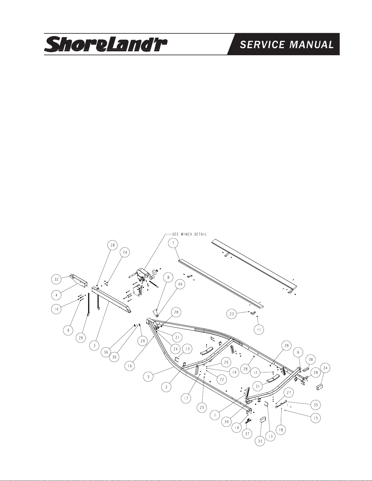
®
SLV24BLW
REF# PART# DESCRIPTION QTY
1 60047-- ADJ BUNK BRKT ................................... 4
2 6046200 ADJUSTABLE BUNK CLAMP ............... 4
- 64145 BRAKELINE ASSY 186" W/COILS ...... 1
3 65541-- TONGUE 3X5X55 .................................. 1
4 65542-- OUTER HOUSING - UFP ACTUATOR . 1
- 65601 BRAKELINE ASSY 56" ......................... 1
5 66102-- FRAME WMENT 80 WIDE 190 LONG .. 1
6 66128-- REAR CROSS WMENT (80 WIDE) ....... 1
7 66408 BUNK ASSY W/BRKTS 10 FT .............. 2
8 0110096 HH 1/2-20 X 1-1/2 .................................. 1
9 0110114 HH 1/2-13 X 4 CS GR5 .......................... 4
10 0110120 HH 1/2-13 X 5 CS GR5.......................... 1
11 0140040 HH 3/8-16 X 1 CS GR5.......................... 4
12 0210130 CARR 3/8-16 X 3 3/4 GR5 .................... 2
13 0310228 SUB 1/2 X 3 9/16 X 4 1/4 ...................... 4
14 0810126 SCREW SELFTAP TYPE B 1/4X1/2 ..... 4
15 0810925 SCRW SELFDRILL HWH #10-16 X 3/4 2
16 0810945 SCREW SELFDRILL 1/4-14X3/4 ......... 1
17 1310040 LOCKWASHER 1/2 S/T MED................ 8
18 1310170 WASHER #10 USS FLAT ...................... 2
19 1340030 LOCKWASHER 3/8 S/T MED................ 2
20 1340095 WASHER USS FLAT 3/8 ....................... 2
21 1340100 WASHER USS FLAT 1/2 ....................... 3
#0002814
REF# PART# DESCRIPTION QTY
22 1410109 HEX NUT FINISH 3/8-16 ....................... 2
23 1440101 FLANGE LOCKNUT SMALL 3/8-16 ...... 4
24 1440102 FLANGE LOCKNUT SMALL 1/2-13 ...... 6
25 1440159 HEX NUT FINISH 1/2-13 ....................... 8
26 2220272 CHAIN 8/0 MACH CHAIN 37" W/837 .... 2
27 3510022 GROMMET 7/16IN MOLDED ............... 1
28 3510030 GROMMET 7/8IN MOLDED ................. 10
29 3510122 LIGHT BEZEL - WHITE ......................... 2
30 3510158 PLASTIC DRIVE RIVOT ........................ 4
31 3510542 MOLDED REAR CROSSMEMBER PAD2
32 3991012 ACTUATOR INNER (35B) ..................... 1
-- 3991013 ACTUATOR INNER (40TBB) ................ 1
-- 3820060 ACTUATOR INNER (24B, 31B & 40TB) 1
33 5110013 DRY LAUNCH LIGHT ASSY (LEFT) ..... 1
34 5110014 DRY LAUNCH LIGHT ASSY (RIGHT) .. 1
35 5110045 3 LIGHT CLUSTER 1994 LEXAN ....... 1
36 5110112 MARINE YELLOW CLEARANCE LIGHT2
37 5110348 BO LICENSE PLATE BRACKET ........... 1
- 5110347 HARNESS 5-PRONG FLAT ................ 1
- 5110354 HARNESS FRAME 2X4 LEFT 17FT 2 .. 1
- 5110355 HARNESS FRAME 2X4 RIGHT 17FT 2 1
38 S-3390 STEP PAD RIGHT 2 1/2 X 7 .............. 1
39 S-3391 STEP PAD LEFT 2 1/2 X 7 ................. 1
40 S-3510 TONGUE COVER PLATE ..................... 1
Made in the USA Midwest Industries, Inc. Ida Grove, IA 51445 (800)859-3028 0002841
www.shorelandr.com REV B 10/25/00
Page 4

Final Assembly Instructions
Remove the small parts from the frame by cutting the bands.
Remove the bolt bag and sort all nuts and bolts by size.
Tongue:
Remove the tongue assembly from the frame bundle and install
into the tongue channel and secure with a 1/2 X 4 hex bolt in the
side of the tongue and tongue channel. Secure with a 1/2 flange
lock nut.
Place the tongue cover over the rear of the tongue and tongue
channel and secure with a 1/2 X 1-1/2 hex bolt,
1/2 flat washer and 1/2 hex nut.
Tongue Wires:
Install the tongue wire harness through the top forward wire hole
and exit the rear of the tongue channel on the frame. Install
grommets and plug the tongue wire into the frame harness by
color.
Actuator & Safety Chain:
Slide the actuator (Ref.#32) into the actuator housing unit
(Ref.#4) and secure with two pins and snap rings provided
with the actuator. Secure the actuator-housing unit to the
front of the tongue using three-(3) ½ X 4 hex bolts and ½
flange lock nuts. Using a ½ X 5 hex bolt on lower right
mounting hole on tongue, secure the safety chain. Place a
½ flat washer on ½ X 5 hex bolt followed by one safety
chain and insert into actuator housing unit and tongue.
Place the second safety chain on the bolt followed by a ½
flat washer and ½ flange lock nut. Tighten.
Brakes:
Refer to the brake manual for service and maintenance.
Bunks:
Mount and secure the bunk assemblies to the adjustable
bunk brackets with 3/8 X 1 hex bolts and 3/8 flange lock
nuts. Make sure the bunks are positioned so that the bunk
bracket attached to the bunk and the bracket attached to
the frame are mounted together so that you have metal to
metal stops to keep the bunks from pivoting to far. Tighten
as far as possible but still allow the bunks to fully pivot side
to side.
DO NOT OVER TIGHTEN - the bunks must pivot freely to
conform to the boats hull.
Page 5
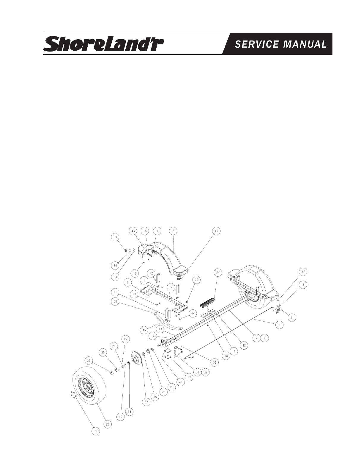
®
Chassis - 31B
REF# PART# DESCRIPTION QTY
1 4279 SHIM PAD U BOLT 12GA FRAME ..... 4
2 62201-- FENDER 10IN POLY ........................... 2
3 6234710 BRAKELINE CLIP BRACKET................ 1
4 66155-- AXLE WMENT (80 WIDE) ..................... 1
5 66162-- SPRING BRKT 10IN SINGLE .............. 2
6 66439-- AXLE ASSY 80 WIDE W/BRAKES........ 1
7 66472 BRAKE LINE ASSY 105" ....................... 1
8 0110170 HH 9/16-18 X 3 1/4 CS GR5 ................. 4
9 0140040 HH 3/8-16 X 1 CS GR5 .......................... 8
10 0210130 CARR 3/8-16 X 3 3/4 GR5 .................... 1
11 0310170 SUB 1/2" X 2-5/16"X6-1/2...................... 4
12 0310276 SUB 1/2 X 2 9/16 X 6 1/2 ...................... 4
13 0610042 SOCKET HEAD SCREW 7/16-20X1-1/4 4
14 1310035 LOCKWASHER 7/16 S/T ....................... 4
15 1310163 WASHER 1.377 OD X .390 ID .............. 8
16 1340206 WASHER 1.5 OD X .765 ID X .186/.206 2
17 1410229 HEX LUGNUT 1/2-20 13/16 OD Z&U.... 10
18 1440101 FLANGE LOCKNUT SMALL 3/8-16 ...... 9
19 1440102 FLANGE LOCKNUT SMALL 1/2-13 ...... 16
20 1440259 HEX LOCKNUT 9/16-18 GRA ............... 4
21 1440349 HEX NUT SLOTTED PLAIN .................. 2
22 1540038 COTTER KEY 1/8 X 1 1/2 ..................... 2
23 3510122 LIGHT BEZEL - WHITE ......................... 4
REF# PART# DESCRIPTION QTY
24 3510132 AXLE PAD 12IN BLK ............................ 1
25 3510158 PLASTIC DRIVE RIVOT ........................ 8
26 4300198 ST215/75R 14C TIRE/GALV DIR RIM .. 2
-- 4300199 ST/215/75R 14C TIRE/MSLVR DIR RIM 2
27 4410089 SPINDLE SLEEVE 1 1/4-3/4IN BRG..... 2
28 4410130 SEAL 1 3/8IN ........................................ 2
29 4410246 SL BEARING PROTECTOR BRA ......... 2
30 4410247 BEARING BUDDY - SS ......................... 2
31 4410289 DISC BRAKE CALIPER ASSY .............. 1
32 4410290 DISC BRAKE CALIPER ASSY .............. 1
33 4410291 HUB/VENTED ROTOR, C.B., ASSY,13 2
34 4440160 ROLLER BEARING 1 1/16IN .............. 2
35 4440170 ROLLER BEARING 1 3/8IN ................ 2
36 4510506 PLUG ..................................................... 1
37 4510518 HOSE CLIP - 1457-YZ ........................... 1
38 4610048 SPRING 5 LEAF HOOK ....................... 2
39 5110112 MARINE YELLOW CLEARANCE LITE . 2
40 5110113 MARINE RED CLEARANCE LIGHT...... 2
41 4510511 HOSE - 18IN MALE-FEMALE BRAKE .. 1
42 S-3387 2" PLASTIC CHANNEL BRACKET ....... 1
43 S-3501 RUBBER CUP WASHER ....................... 8
44 S-3207G SPRING BRKT BUSH PLATED ZYU .... 2
45 S-3409G SPRING CLAMP 1/4X1 1/2X4 ZYU ... 2
46 S-3449G SPRING AND AXLE U-BOLT PLATE.... 2
Made in the USA Midwest Industries, Inc. Ida Grove, IA 51445 (800)859-3028 0002845
www.shorelandr.com REV A 11/01/00
Page 6

Place one of the spring bushings (Ref.#44) into the rear of the
spring bracket (Ref.#5) and secure with a 9/16 X 3-1/4 hex bolt
(Ref.#8) and 9/16 hex lock nut (Ref.#20). Repeat on the other
side. Position the axle (Ref.#4) under the frame, then hook the
spring loop around the bushing just installed. Raise the axle
assembly up so the front of the springs (Ref.#38) line up with the
front spring bracket hole. Insert the other two (2) 9/16 X 3-1/4
hex bolts and 9/16 hex lock nuts. Tighten all nuts and bolts, but
do not over tighten. Allow the spring room enough to move.
Mount the tires and rim assemblies (Ref.#26) using 80-90 ft. lbs.
tongue on lug nuts (Ref.#17) using proper tightening procedures.
Refer to the brake manual for service and maintenance.
Tire Size & Carrying Capacity Chart
Tire Load Carrying
Size Range Capacity
ST215/75R14 C 1870 lbs. per/tire
Refer to the tire side wall for the correct tire pressure.
Page 7

®
55 Brake Tongue Assembly (S-TS)
REF# PART# DESCRIPTION QTY
1 65541-- TONGUE 3X5X55.................................. 1
2 65542-- OUTER HOUSING - UFP ACTUATOR 1
3 65601 BRAKELINE ASSY 56" ......................... 1
4 0110114 HH 1/2-13 X 4 CS GR5 ......................... 3
5 0110120 HH 1/2-13 X 5 CS GR5 ......................... 1
6 1340100 WASHER USS FLAT 1/2 ....................... 2
7 1440102 FLANGE LOCKNUT SMALL 1/2-13 ...... 4
8 2220272 CHAIN 8/0 MACH CHAIN 37" W/837 ... 2
9 3510030 GROMMET 7/8IN MOLDED ................ 1
10 3991012 ACTUATOR INNER DRUM BRAKE ..... 1
-- 3991013 ACTUATOR INNER DISC - TANDEM .. 1
-- 3820060 ACTUATOR INNER DISC - SINGLE .... 1
11 5110349 HARNESS TONGUE 7FT ................... 1
Actuator & Safety Chain:
Slide the actuator (Ref.#10) into the actuator housing unit (Ref.#2)
and secure with two pins and snap rings provided with the
actuator. Secure the actuator-housing unit to the front of the
tongue using three-(3) ½ X 4 hex bolts and ½ flange lock nuts.
Using a ½ X 5 hex bolt on lower right mounting hole on tongue,
secure the safety chain. Place a ½ flat washer on ½ X 5 hex bolt
followed by one safety chain and insert into actuator housing unit
and tongue. Place the second safety chain on the bolt followed by
a ½ flat washer and ½ flange lock nut. Tighten.
Brakes:
Refer to the brake manual for service and maintenance.
Made in the USA Midwest Industries, Inc. Ida Grove, IA 51445 (800)859-3028 0002856
www.shorelandr.com REV 7/13/00
Page 8

Page 9

®
78 - Brake Tongue Assembly (S-TL)
REF# PART# DESCRIPTION QTY
1 65542-- OUTER HOUSING - UFP ACTUATOR 1
2 65601 BRAKELINE ASSY 56" ......................... 1
3 65607-- TONGUE TUBE 5X3X11 GA X 78IN ..... 1
4 0110114 HH 1/2-13 X 4 CS GR5 ......................... 3
5 0110120 HH 1/2-13 X 5 CS GR5 ......................... 1
6 0810925 SCRW SELFDRILL HWH #10-16 X 3/4 4
7 1340100 WASHER USS FLAT 1/2 ....................... 2
8 1440102 FLANGE LOCKNUT SMALL 1/2-13 ...... 4
9 2220272 CHAIN 8/0 MACH CHAIN 37" W/837 ... 2
10 3510030 GROMMET 7/8IN MOLDED ................ 1
11 3991012 ACTUATOR INNER DRUM BRAKE..... 1
-- 3991013 ACTUATOR INNER DISC - TANDEM .. 1
-- 3820060 ACTUATOR INNER DISC - SINGLE .... 1
12 5110127 REFLECTOR ANDERSON AMBER ..... 2
13 5110349 HARNESS TONGUE 7FT ................... 1
14 5110456 LIGHT AMBER SIDE MARKER 36 ...... 2
Actuator & Safety Chain:
Slide the actuator (Ref.#11) into the actuator housing unit (Ref.#1)
and secure with two pins and snap rings provided with the
actuator. Secure the actuator-housing unit to the front of the
tongue using three-(3) ½ X 4 hex bolts and ½ flange lock nuts.
Using a ½ X 5 hex bolt on lower right mounting hole on tongue,
secure the safety chain. Place a ½ flat washer on ½ X 5 hex bolt
followed by one safety chain and insert into actuator housing unit
and tongue. Place the second safety chain on the bolt followed by
a ½ flat washer and ½ flange lock nut. Tighten.
Brakes:
Refer to the brake manual for service and maintenance.
Made in the USA Midwest Industries, Inc. Ida Grove, IA 51445 (800)859-3028 0002857
www.shorelandr.com REV 7/13/00
Page 10

Page 11

®
65 - Brake Tongue Assembly (S-TM)
REF# PART# DESCRIPTION QTY
1 65542-- OUTER HOUSING - UFP ACTUATOR 1
2 65601 BRAKELINE ASSY 56" ......................... 1
3 65604-- TONGUE TUBE 5X3X7 GA X 65IN ...... 1
4 0110114 HH 1/2-13 X 4 CS GR5 ......................... 3
5 0110120 HH 1/2-13 X 5 CS GR5 ......................... 1
6 1340100 WASHER USS FLAT 1/2 ....................... 2
7 1440102 FLANGE LOCKNUT SMALL 1/2-13 ...... 4
8 2220272 CHAIN 8/0 MACH CHAIN 37" W/837 ... 2
9 3510030 GROMMET 7/8IN MOLDED ................ 1
10 3991012 ACTUATOR INNER DRUM BRAKE ..... 1
-- 3991013 ACTUATOR INNER DISC - TANDEM .. 1
-- 3820060 ACTUATOR INNER DISC - SINGLE .... 1
11 5110349 HARNESS TONGUE 7FT ................... 1
Actuator & Safety Chain:
Slide the actuator (Ref.#10) into the actuator housing unit (Ref.#1)
and secure with two pins and snap rings provided with the
actuator. Secure the actuator-housing unit to the front of the
tongue using three-(3) ½ X 4 hex bolts and ½ flange lock nuts.
Using a ½ X 5 hex bolt on lower right mounting hole on tongue,
secure the safety chain. Place a ½ flat washer on ½ X 5 hex bolt
followed by one safety chain and insert into actuator housing unit
and tongue. Place the second safety chain on the bolt followed by
a ½ flat washer and ½ flange lock nut. Tighten.
Brakes:
Refer to the brake manual for service and maintenance.
Made in the USA Midwest Industries, Inc. Ida Grove, IA 51445 (800)859-3028 0002858
www.shorelandr.com REV 7/13/00
Page 12

Page 13

®
Profile 2000 Winch Assembly
REF# PART# DESCRIPTION QTY
1 6081610 WINCH POST SPACER ............................ 1
2 60930-- WINCH POST 7IN ................................... 1
3 6107503 END CAP - BLACK PROFILE 2000 .......... 2
4 65657-- WINCH HOLDER CASE ........................... 1
5 65659-- PROFILE 2000 WINCH CASE ASSY ....... 1
6 0110064 HH 3/8-16 X 5 CS GR5 ............................. 1
7 0110118 HH 1/2-13 X 4 1/2 CS GR5 ....................... 5
8 0110125 HH 1/2-13 X 5 1/2 CS GR5 ....................... 1
9 204009 SHAFT BUSHING DL1400/2500 .............. 2
10 204360 SPACER WASHER DL1602 ..................... 1
11 204808 REEL SPACER DL1700 ........................... 1
12 204809 HANDLE HUT DL1602 ............................. 1
13 205014 LOCK NUT DL1400/1700/1802/2500 ....... 1
14 205116 E-RING DL1602/1700/2500 ....................... 1
15 205126 HH 3/8-16 X 5 CS GR5 ............................. 1
16 205139 SPACER WASHER DL1700/1802/2500 .... 1
17 205269 RATCHET PAWL BOLT 1/4-20 X 5 ........... 1
18 205270 LOCKNUT 3/8-16 JAM STYLE - WINCH . 1
19 206281 EXTENSION SPRING DL1400-2500 BLU 1
20 0210102 CARR 3/8-16 X 1 GR5 .............................. 1
21 304731 DRIVE SHAFT UPPER DL1802 .............. 1
22 404868 REVERSABLE RATCHET PAWL .............. 1
23 404872 RACHET SPACER DL1700/2500 ............ 1
24 404878 RATCHET SLEEVE DL1700/2500 ........... 1
25 1340095 WASHER USS FLAT 3/8 ........................... 1
26 1440101 FLANGE LOCKNUT SMALL 3/8-16 .......... 2
27 1440102 FLANGE LOCKNUT SMALL 1/2-13 .......... 6
28 2210145 CHAIN 1/4(7MM)X 10 LINKS .................... 1
29 3110237 WINCH HANDLE DL1802 ........................ 1
30 3110348 WINCH REEL W/STRAP DL1800/1802 ... 1
31 3510065 4" BOW ROLLER - BLACK ....................... 1
32 3520011 PLUG 3/8IN WHITE PLASTIC ................. 4
33 3520019 PLUG 1IN WHITE PLASTIC .................... 2
34 LH308 CUP WASHER .......................................... 2
35 S-3374 NYLN WINCH CASE BUSH-3/4ODX4.25 1
Winch Post Assembly:
Mount the winch post to the tongue in the desired position and
secure with three (3) 1/2” X 4” carriage bolts and 1/2” flange lock
nuts. Mount the winch handle on the winch shaft using the special
hardware provided with the winch.
Winch Post Adjustment:
Before adjusting the winch post check to see that the transom of
the boat is flush with the rear of bunks. Slide the winch post into
position. NOTE: The winch holder (upper portion) must be
positioned just above the bow eye. Run the winch strap over the
upper nylon bushing in the winch case and secure to the bow eye.
Tighten all bolts on the winch post. Slip the bow eye safety chain
into the bow eye. Adjustment is complete.
Made in the USA Midwest Industries, Inc. Ida Grove, IA 51445 (800)859-3028 0002814
www.shorelandr.com
REV - 7/11/00
Page 14

 Loading...