

Page 1
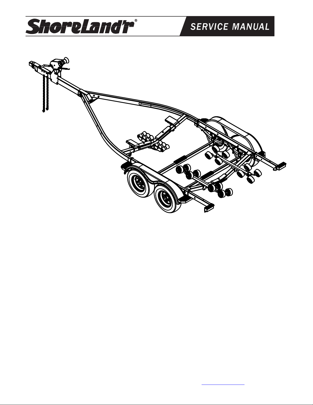
SLR40TCBLW-__ & SLR40TCBBLW-__
SLR40TCBLW-__ Shown
SLR40TCBLW Bundles Required:
66520 Bag with Chains, No Coupler.....................1
69082 Lit Packet Brake Trailers............................1
80774-- Frame Bundle - 2X4W R40TCBLW...........1
66996-- Tongue Assembly 55”, W/UFP Actuator....1
TA0991-__ Winch Stand Kit 9” W/Mtg Hdwe…….……1
TA0992-__ Winch Stand Kit 9” W/Mtg Hdwe……….…1
TA0993-__ Winch Stand Kit 7” W/Mtg Hdwe…….……1
ST215/75R14C Tire/TS Dir Rim................4
(or)
ST215/75R14C Tire/Galv Dir Rim..............4
(or)
(or)
SLR40TCBBLW Bundles Required:
ST215/75R14C Tire/TS Dir Rim................4
(or)
ST215/75R14C Tire/Galv Dir Rim..............4
66520 Bag with Chains, No Coupler.....................1
69082 Lit Packet Brake Trailers............................1
80775-- Frame Bundle - 2X4W R40TCBBLW.........1
66996-- Tongue Assembly 55”, W/UFP Actuator....1
69352 Brake Kit Tandem Axle Connect………….1
TA0991-__ Winch Stand Kit 9” W/Mtg Hdwe……….…1
(or)
TA0992-__ Winch Stand Kit 9” W/Mtg Hdwe……….…1
(or)
TA0993-__ Winch Stand Kit 7” W/Mtg Hdwe……….…1
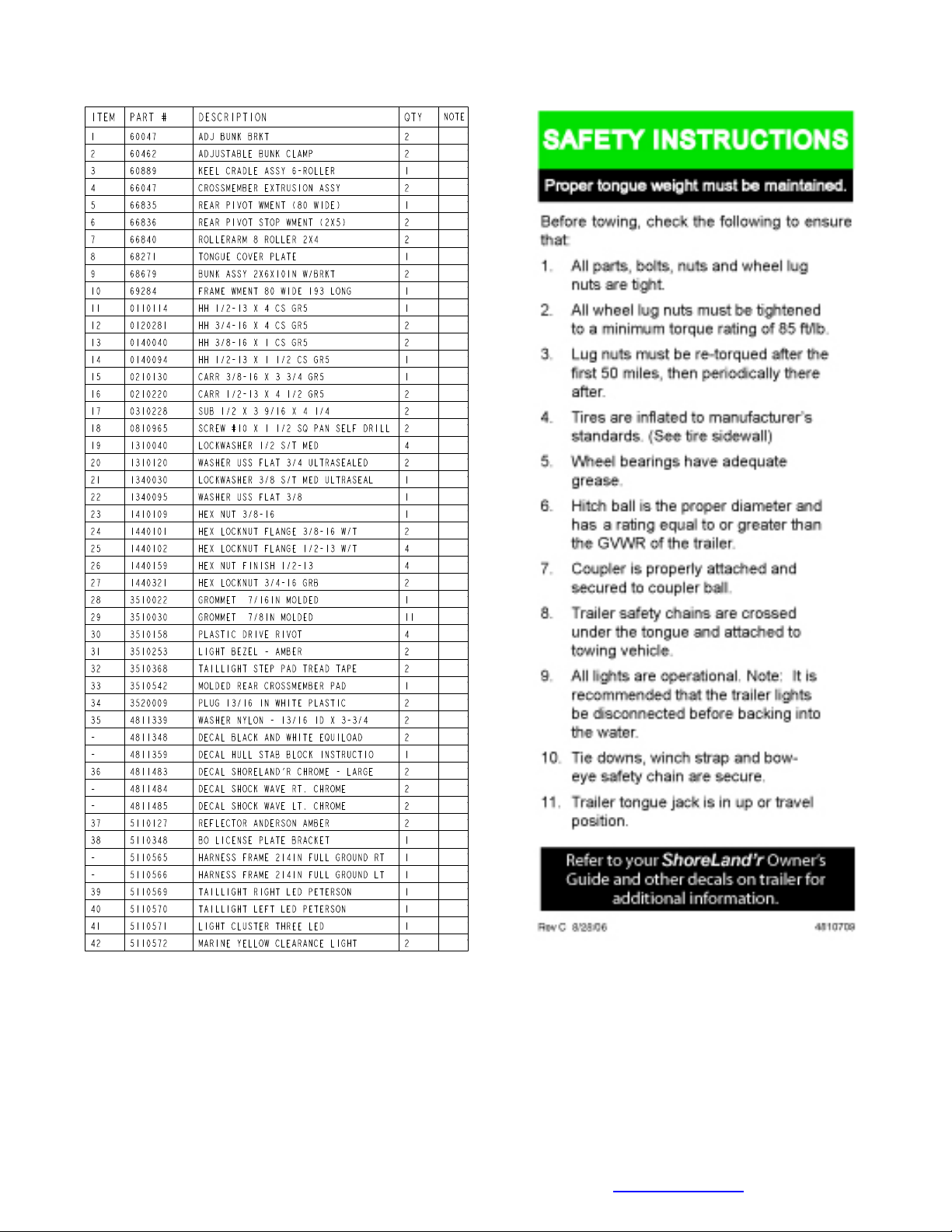
ShoreLand’r offers their product line in either galvanized or painted finis h. When ordering parts it is important that you
specify the finish or color you have on your prod uct. The five (5) digit number along with a two (2) digit space _ _, no te
the parts which can be purchased with various finishes. When ordering these items use the five (5) digit number along
with a two (2) digit suffix for the proper finish.
00..........Galvanized
01..........Arctic White
03..........Black
Midwest Industries, Inc. Ida Grove, IA 51445 800-859-3028 www.shorelandr.com 0004264
Page 1 of 16 9/28/2010
Page 2
Midwest Industries, Inc. Ida Grove, IA 51445 800-859-3028 www.shorelandr.com 0004264
Page 2 of 16 9/28/2010
Page 3
FINAL ASSEMBLY INSTRUCTIONS
Remove the hardware bag from the frame, remove
parts and sort by size.
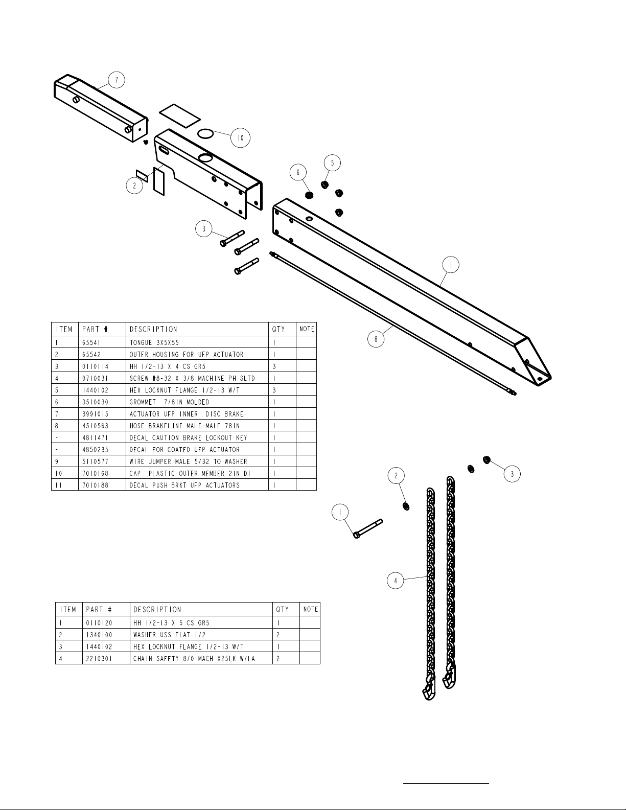
TONGUE
The tongue is shipped separate of the frame. Locate
the appropriate tongue and install by sliding it in the
front of the tongue channel.
Line the holes in the tongue with the holes in the
tongue channel. Install the 1/2” x 4” hex bolt in the
front cross hole and secure with a 1/2” lock nut.
Remove the wire harness from the rear of the tongue.
Place the wire harness and the brake line through the
hole provided in the tongue cover plate.
Midwest Industries, Inc. Ida Grove, IA 51445 800-859-3028 www.shorelandr.com 0004264
Page 3 of 16 9/28/2010
Page 4
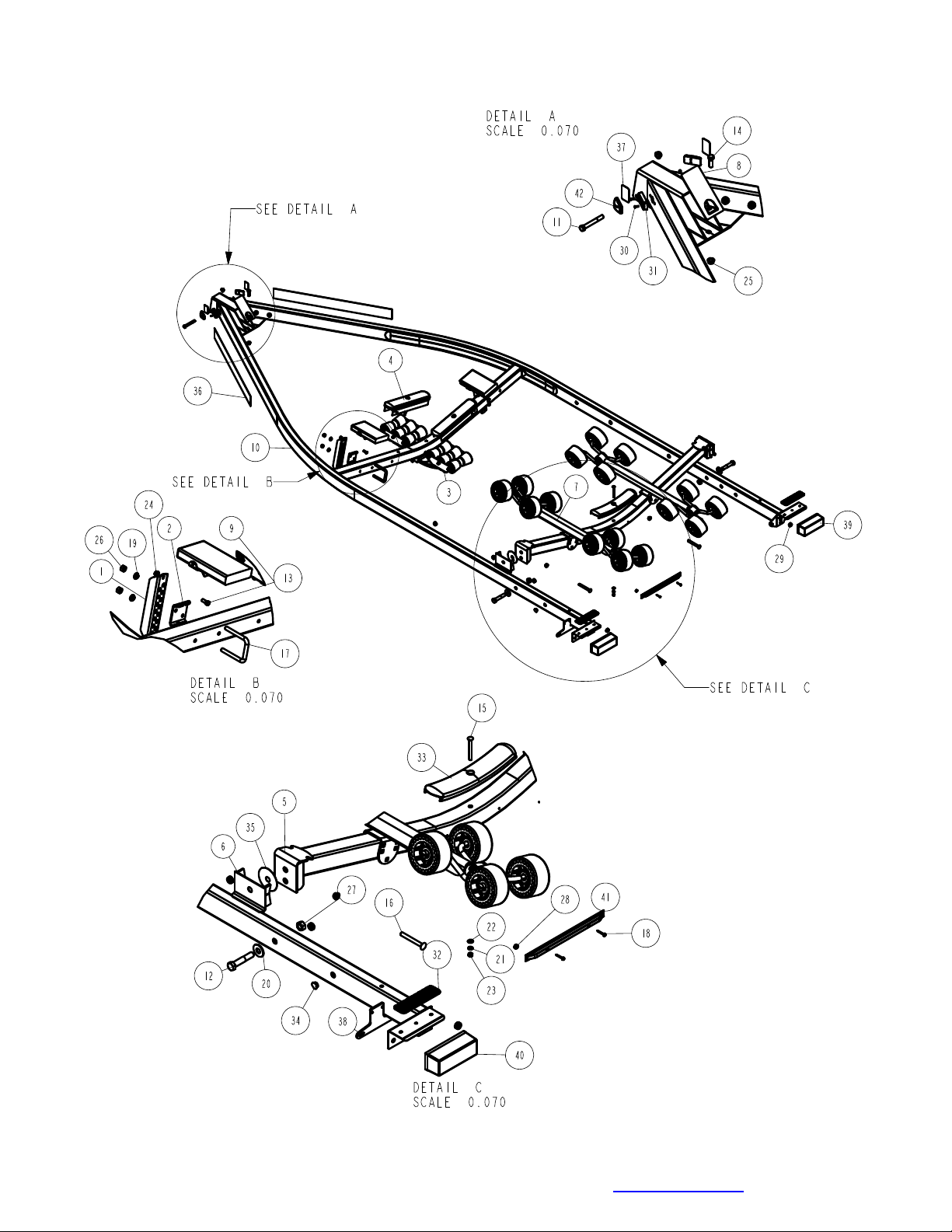
See Detail A in Diagram A. Secure the tongue cover plate in position
with the same 1/2” x 1-1/2” hex bolt that secures the back on the
tongue to the tongue channel of the frame. Secure with 1/2” lock nut.
Tighten both bolts just installed.
Plug the tongue wire harness ends into the frame harnesses by
matching colors and ends. Push the extra wire provided into the rear
of the tongue or remove the grommet in the side frame and place the
extra wire in the side frame. Replace grommet just removed.
SAFETY CHAINS
Locate the 1/2” x 1-1/4” hex bolt. Slip the bolt through a 1/2” at washer, then
place through the last link of one of the safety chains. Place a second flat
washer on the bolt and insert through the hole as shown in Diagram B. Secure
with a 1/2” flange lock nut. Tighten. Repeat this process on the second safety
chain on the opposite side of the tongue. Assembly is complete.
Midwest Industries, Inc. Ida Grove, IA 51445 800-859-3028 www.shorelandr.com 0004264
Page 4 of 16 9/28/2010
Page 5
WINCH POST ASSEMBLY
The height that the bow eye is placed in your boat will
determine the length winch post required. Once this is
determined, attach the winch base to the tongue with
three 1/2” x 4-1/2” carriage bolts and lock nuts.
Align the holes in the Profile 2000 mounting channel
with the holes in the top of the winch base. Attach the
front of the winch head mounting channel to the base by
placing a 1/2” x 4-1/2” hex bolt through the hole closest
to the front of the winch base. Secure with a lock nut. Do
not tighten.
Note that the winch head can now be rotated either up
or down. Identify the correct hole combination to use
to position the bow eye roller just above the bow eye
of your boat. When determined, secure in this position
by placing the bushing as shown in Diagram C inside
the winch base so it aligns with the hole just identified
for the proper adjustment. Insert another 1/2” x 4-1/2”
hex bolt through the determined mounting hole in the
mounting channel and winch base making sure the
bolt passes through the bushing as well. Secure with
a 1/2” lock nut.
Tighten all bolts.
Midwest Industries, Inc. Ida Grove, IA 51445 800-859-3028 www.shorelandr.com 0004264
Page 5 of 16 9/28/2010
Page 6

Midwest Industries, Inc. Ida Grove, IA 51445 800-859-3028 www.shorelandr.com 0004264
Page 6 of 16 9/28/2010
Page 7

Midwest Industries, Inc. Ida Grove, IA 51445 800-859-3028 www.shorelandr.com 0004264
Page 7 of 16 9/28/2010
Page 8

R SERIES
The R-series roller rack is installed by placing the roller
arm assembly mounting channel over the rear cross
member and securing in place with a 1/2” x 4-1/2” hex
bolt and lock nut. (See Diagram A). Note that it should
be left loose until the boat is placed on the trailer. Once
the proper position is determined, it may be tightened.
Repeat on the other roller arm assembly.
The short stabilizer bunk is installed to the adjustable
bunk bracket on the front cross member with a 3/8” x 1”
hex bolt and lock nut. (See Diagram A).
Midwest Industries, Inc. Ida Grove, IA 51445 800-859-3028 www.shorelandr.com 0004264
Page 8 of 16 9/28/2010
Page 9

Tandem Axle Single Brake with Custom Fender Assembly
Midwest Industries, Inc. Ida Grove, IA 51445 800-859-3028 www.shorelandr.com 0004264
Page 9 of 16 9/28/2010
Page 10

Tandem Axle Double Brake with Custom
Fender Assembly
Midwest Industries, Inc. Ida Grove, IA 51445 800-859-3028 www.shorelandr.com 0004264
Page 10 of 16 9/28/2010
Page 11

ROCKER ARMS
Locate the rocker arms (Ref. No. 6 of Detail A in Diagram D.) Note that the center bushing has a grease zerk
in it. Position the rocker arms up into the center channel
welded in the center of the tandem spring bracket so
that the grease zerk is pointing down. Align the holes in
the channel with the rocker arm. Secure in place with a
3/4” x 4-1/2” hex bolt and lock nut. Tighten. Repeat this
process on the other rocker arm and spring bracket.
Grease the rocker at this time by applying grease
through the zerk just discussed.
NOTE: The grease zerk is positioned down so that it
is accessible for servicing when needed.
SPRINGS
Position the axles so they are properly aligned with
the trailer. Position the brake axle so that the disc
brake calipers are on the back side of the axle. The
brake axle must always be mounted as the rear axle
to give you the best braking possible (See Diagram
D.) There is no right and left to the axle without
brakes. It can be mounted either way.
Place the springs on the topside of the spring pads
welded to the axle. (See chassis diagram). Note that
the hook end of the spring must be to the rear of the
trailer. Place a spring clamp on the top center of the
spring as shown. Next place the 1/2” x 6-1/2” U-bolts
down over the top of the spring clamp, spring and
axle as shown.
Place the spring and axle U-bolt plate onto the ends
of the two U-bolts just placed. Secure in place with
1/2” lock nuts.
Thread onto the U-bolts but do not tighten securely
until the complete unit is in position on the trailer. Repeat on the other spring.
AXLE
Place one of the spring bracket bushings into the
rear of the spring bracket and secure with a 9/16” x
3-1/4” hex bolt and hex lock nut. Repeat in other
spring bracket.
Position the rear axle under the frame, then hook the
loop of the springs around the bushings just
installed.
Note that if the axle is positioned too low when trying
to hook, the loops will not hook around the bushings.
Raise the front of the springs up so they align with
the rear hole in the axle boogie just installed. Secure
in place with 9/16” x 3-1/4” hex bolts and lock nuts.
Install another spring bracket bushing in the front
hole on the rock arm assemblies. Secure with a
9/16” x 3-1/4” hex bolt and lock nut. Tighten.
Hook the hook end of the springs mounted to the
front axle over the bushing just installed in the rocker
arm assembly. Swing the front of the spring up and
attach the front mounting hole in the spring bracket
with another 9/16” x 3-1/4” hex bolt and lock nut.
Tighten all axle U-bolts and spring bolts.
Midwest Industries, Inc. Ida Grove, IA 51445 800-859-3028 www.shorelandr.com 0004264
Page 11 of 16 9/28/2010
Page 12

BRAKE LINE
Locate the brass brake line coupling. Remove the
plastic cap and thread the brake hose coming out the
rear of the tongue into one end of the coupling. Once
aligned, thread the side frame brake hose into the
other end of the coupling. Tighten both lines into the
coupling.
ONE AXLE BRAKE INSTALLATION
Cut the tape securing the brake line hose to the axle.
Remove the plastic plug from the bottom port in the
brass blocks of both brake calipers. Thread in the
brake hose male end and tighten to either 6-8 ft. lb. or
72-96 in. lb. of torque.
DO NOT OVER TIGHTEN Over tightening will cause
the brass block to crack and then leak.
Remove the plastic cap from the end of the frame
brake hose coming out of the side frame by the axle.
Carefully pull the brake hose so that it can be
threaded thru the brake line bracket. The brake hose
will then be routed down to the side port in the brass
block on the right caliper. Thread the brake hose
fitting into the brass block. Tighten.
NOTE: The complete brake system including the axle
MUST be bled to ensure that all air has been removed
from the brake system.
For bleeding instructions see the UFP brake bleeding
manual or the ShoreLand’r Disc Brake Manual.
Fill the actuator reservoir with brake fluid and bleed
the line per the instructions in the Brake Manual.
TIRE & WHEEL ASSEMBLY
Mount the tire and wheel assemblies using the 1/2”
fine threaded tapered lug nuts provided. Tighten to
85-95 ft./lb. torque using the rotation pattern as shown
in the ShoreLandr’s Owners Manual.
Re-torque the lug nuts after 50 miles driving and then
periodically thereafter
DUAL AXLE BRAKE INSTALLATION
If your trailer is equipped with dual axle brakes connect the line to the axle as follows:
Cut the tape securing the brake line hose to the axle.
Remove the plastic plug from the bottom port in the
brass blocks of both brake calipers. Thread the brake
hose male end into the block and tighten to either 6-8
ft. lb. or 72-96 in. lb. of torque.
DO NOT OVER TIGHTEN Over tightening will
cause the brass block to crack and then leak.
Attach the brake hose from the connecting kit to the
side port right side of rear axle .Route from the axle
to the spring bracket with the U-shaped hose clip.
Once the brake hoses are secured in place the
lines can be attached.
Locate the brass tee connector. Screw the male
port of the tee into the brake line hose. Tighten.
Next connect the side frame brake hose into the top
port on the tee. Connect the two axles together
using the 42” brake hose supplied. Thread one end
of the hose into the brass tee just installed. Route
the hose over to the other brake line clip on the
spring bracket and then down to the side port in the
brass block on the right caliper of the axle, form a
loop using the extra hose in the line and using the
included clips and screws attach the hose to the
side frame to keep it up out of the way. Tighten to
either 6-8 ft. lb. or 72-96 in. lb. of torque.
DO NOT OVER TIGHTEN Over tightening will
cause the brass block to crack and then leak.
NOTE: The complete brake system including the
axle MUST be bled to ensure that all air has been
removed from the brake system.
For bleeding instructions see the UFP brake
bleeding manual or the ShoreLand’r Disc Brake
Manual.
Fill the actuator reservoir with brake fluid and bleed
the line per the instructions in the Brake Manual.
TIRE & WHEEL ASSEMBLY
Mount the tire and wheel assemblies using the 1/2”
fine threaded tapered lug nuts provided. Tighten to
85-95 ft./lb. torque using the rotation pattern as
shown in the ShoreLandr’s Owners Manual.
Re-torque the lug nuts after 50 miles driving and
then periodically thereafter.
Midwest Industries, Inc. Ida Grove, IA 51445 800-859-3028 www.shorelandr.com 0004264
Page 12 of 16 9/28/2010
Page 13

Midwest Industries, Inc. Ida Grove, IA 51445 800-859-3028 www.shorelandr.com 0004264
Page 13 of 16 9/28/2010
Page 14

Midwest Industries, Inc. Ida Grove, IA 51445 800-859-3028 www.shorelandr.com 0004264
Page 14 of 16 9/28/2010
Page 15

TRAILER ADJUSTMENTS
The adjustment of the trailer to your boat is very important not only for the trailer, but also the boat. Failure to do so may lead to potential failure or damage
to either the trailer or boat.
Adjust as follows:
AXLE ADJUSTMENT
The amount of tongue weight on your trailer can be
adjusted as follows:
To lower the tongue weight, adjust the axle assembly
forward. To increase the tongue weight, adjust the
axle backward.
The distance that the axle assembly has to be
moved will vary because it is directly related to the
weight and center of gravity of the boat placed on it.
Best towing is achieved when the tongue weight is 57% of the total gross load of the complete unit.
Note: Wire harnesses and brake line lines will need
care when moving the axle assembly.
REAR SUPPORT SYSTEM
Place the boat on the trailer so that the transom is
located at the rear of the support system. On a bunk
trailer, the transom of the boat should be within 1-2”
of the end of the bunk. This gives you maximum
support on the transom.
The rear cross member is adjustable forward or
backward to allow the trailer to be adjusted to
various length boats. This is accomplished by
removing the pivot bolt on holds each end of the rear
pivot to the side frame. Reposition the rear pivot arm
into the other hole position predrilled in the side
frame.
Reattach the rear pivot to the side frame with the
bolts just removed. Tighten.
The wire harness for the three-light identification light
must be repositioned where it comes from the side
frame to the rear pivot to eliminate slack, and
sagging of the wiring.
ROLLERS
Position the roller racks so they are far enough apart
to give your boat stability while transporting. When
the desired width is achieved, move the roller rack
system so that the rollers are just to the outside of a
strake. The rollers need to be adjusted so that you
have a minimum of one to two inches of clearance
between the keel of the boat and the center cross
member pads. This will help center the boat when
loading and unloading.
When the desired position is determined, tighten only
enough to hold the rollers from moving while the
other adjustments are being made. Final tightening
will be done at the end of the adjusting process.
FRONT ROLLER SUPPORT SYSTEM
The keel of the boat must rest on the center of the
front keel roller system creating a three-point support
system. The keel roller system is designed to fit most
boats without needing any further adjustment, however there are considerable differences in boat bottom designs and certain lines of boats will require a
riser. One riser is shipped inside the rear keel guide
roller bracket. This can be removed and bolted on
the bottom side of the keel guide roller bracket so it
is between it and the keel cradle itself. This will raise
the front end of your boat 3/4”. In the event that this
is not enough, an additional one can be added to the
other keel guide roller bracket.
Once the height of the roller cradle assembly is established the stabilizer pads can be adjusted. This is
accomplished by sliding the pad up against the boat
bottom by hand. It is not necessary that they carry
much weight. They are designed to just give your
boat added stability while being towed. It may be
necessary to adjust the assembly up so that they can
be moved further apart giving additional support. Pull
the assembly away from the boat. Place the U-bolt
that holds the assembly to the cross member in a
lower hole in the bracket. Push the assembly back
against the boat. Tighten in position.
WINCH POST
Once all other adjustments are complete the winch
post can be adjusted. Slide the winch post base
backward on the tongue until the bow roller comes in
contact with the boat.
This bow roller needs to be positioned directly above
the boat bow eye to prevent your boat from moving
forward in the event of a sudden stop. It can be
moved up or down by removing the back bolt that
mounts the winch head to the base. When this bolt is
removed, the head can be rotated up or down to
reach the desired height required to fit your boat.
Once in this position, align the closest pair of holes in
the brackets and reinsert the bolt just removed.
Tighten.
Midwest Industries, Inc. Ida Grove, IA 51445 800-859-3028 www.shorelandr.com 0004264
Page 15 of 16 9/28/2010
Page 16

Attach the winch strap and crank winch tight. Attach
the bow eye safety chain into the bow eye of the boat
as well. This is just another level of protection to keep
your boat and trailer together as one unit.
Adjustments are now complete. Double check your
boat for fit. If the desired fit has been achieved, tighten
all fasteners that may have either been left loose or
have been loosened to do the adjusting.
Note: All nuts and bolts must be tightened before towing. The law requires that the white ground wire on
both the tongue wire harness and vehicle harness be
properly grounded to respective trailer and vehicle
frames.
Recheck all fasteners on the complete trailer to make
sure they are all tight and ready for towing. All fasteners should be periodically checked before towing.
See your ShoreLand’r Owner’s Guide for further
technical information regarding your trailer and its
components.
Midwest Industries, Inc. Ida Grove, IA 51445 800-859-3028 www.shorelandr.com 0004264
Page 16 of 16 9/28/2010
 Loading...