

Page 1
®
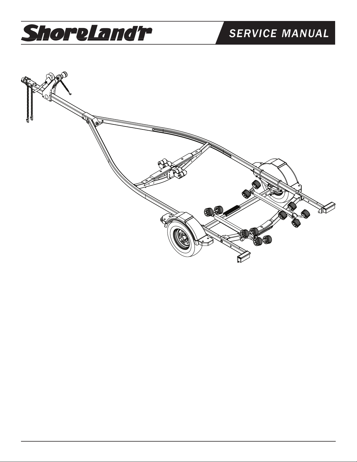
SLR22L
SLR22L Bundles Required
62340 Literature Packet - Trailers
61395 Coupler Bag w/Chains
80419-- Frame Bundle 2x3 R22L
ST185/80R13-C Dir Rim
60493-- Tongue 60” 2x3 Frame
ShoreLand’r offers their product line a painted nish. When ordering
parts it is important that you specify the nish or color you have on
your product. The ve (5) digit number along with a two (2) digit space
_ _, note the parts which can be purchased with various nishes.
When ordering these items use the ve (5) digit number along with
a two (2) digit sufx for the proper nish.
00..........Galvanized
01..........Arctic White
03..........Black
33..........Galvanized w/Black Plastic Components
Midwest Industries, Inc. Ida Grove, IA 51445 800.859.3028 www.shorelandr.com 0003697
Page 1 11/01/06
Table of Contents: Page
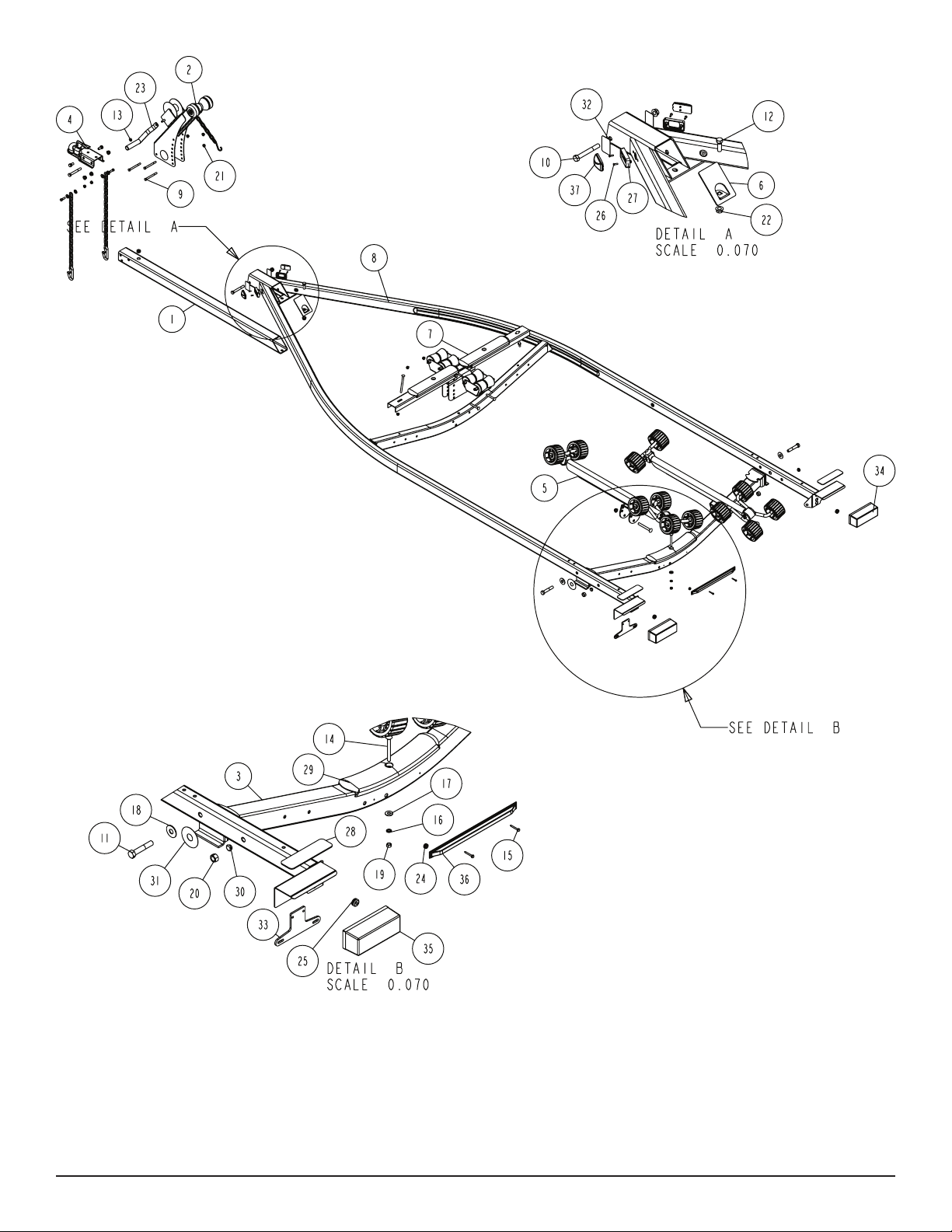
Frame Drawing & Bill of Materials ................................2-3
Safety Instructions ........................................................3
Coupler & Safety Chain Dwg/BOM...............................4
Tongue Assembly Instructions ......................................4
Wire Harness Instructions ............................................4
Safety Chain Assembly Instructions .............................4
Winch Post Assembly Instructions................................4
Winch Dwg/BOM. ......................................................... 5
Chassis Drawing & Bill of Materials ..............................6-7
Spring Assembly Instructions ....................................... 8
Axle Assembly Instructions ...........................................8
Tire/Wheel Assembly ....................................................8
Tire Size & Carrying Capacity Chart .............................8
Roller Dwg/BOM/Assembly Instructions ....................... 9-10
Trailer Adjustments .......................................................11
Axle Adjustments .......................................................11
Rear Support System - Roller ...................................11
Front Support System - Roller ................................... 11
Winch Post Adjustments............................................11
Page 2
Midwest Industries, Inc. Ida Grove, IA 51445 800.859.3028 www.shorelandr.com 0003697
Page 2 11/01/06
Page 3
Refer to your ShoreLand’r Owner’s
Guide and other decals on trailer for
additional information.
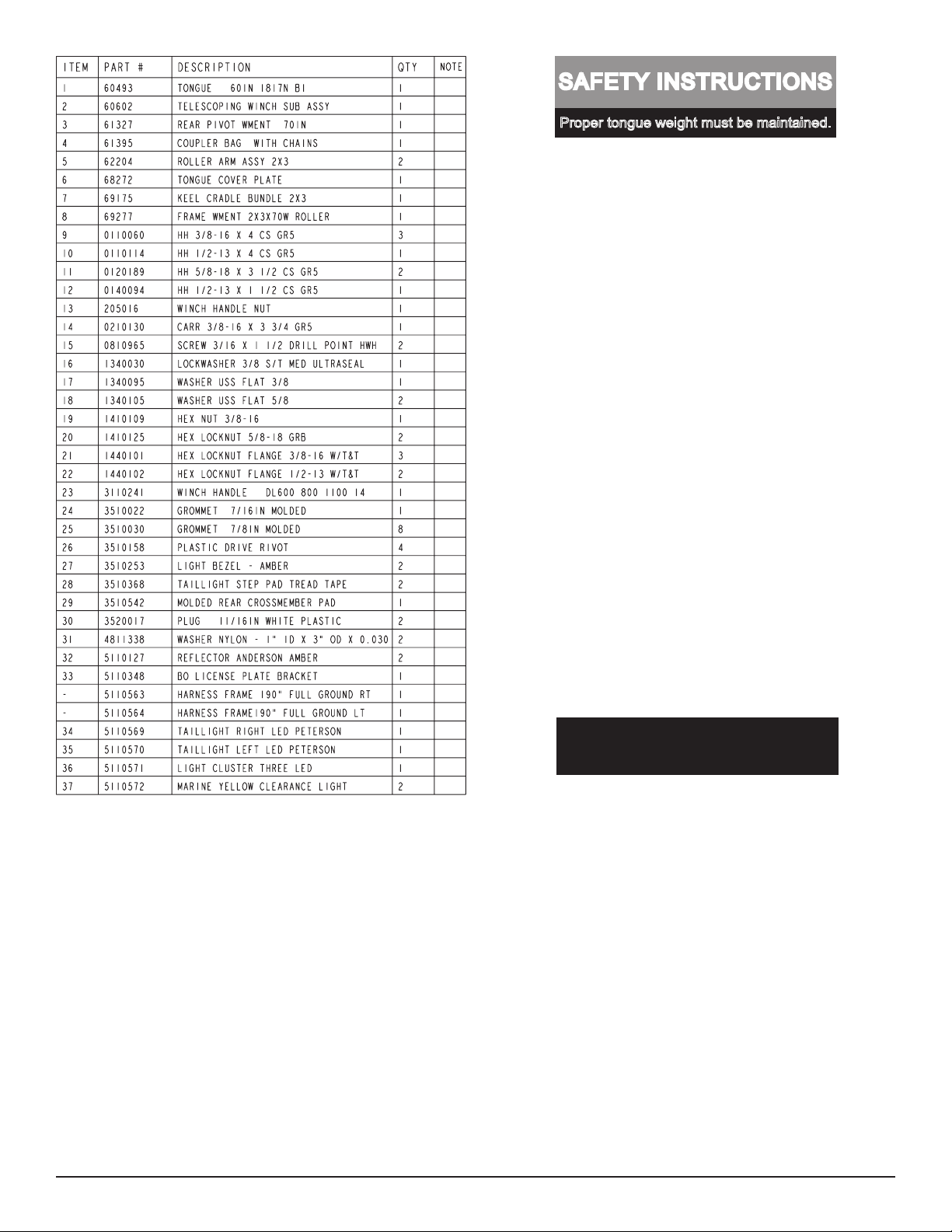
SAFETY INSTRUCTIONS
4810709
Proper tongue weight must be maintained.
Rev C 8/28/06
Before towing, check the following to ensure
that:
1. All parts, bolts, nuts and wheel lug
nuts are tight.
2. All wheel lug nuts must be tightened
to a minimum torque rating of 85 ft/lb.
3. Lug nuts must be re-torqued after the
first 50 miles, then periodically there
after.
4. Tires are inflated to manufacturer’s
standards. (See tire sidewall)
5. Wheel bearings have adequate
grease.
6. Hitch ball is the proper diameter and
has a rating equal to or greater than
the GVWR of the trailer.
7. Coupler is properly attached and
secured to coupler ball.
8. Trailer safety chains are crossed
under the tongue and attached to
towing vehicle.
9. All lights are operational. Note: It is
recommended that the trailer lights
be disconnected before backing into
the water.
10. Tie downs, winch strap and bow eye safety chain are secure.
11. Trailer tongue jack is in up or travel
position.
ASSEMBLY INSTRUCTIONS
Remove all items from the frame. Locate the hardware bag and sort
all items by size.
Midwest Industries, Inc. Ida Grove, IA 51445 800.859.3028 www.shorelandr.com 0003697
Page 3 11/01/06
Page 4
TONGUE
The tongue comes shipped separate of the frame. Locate and slide the
tongue in the front tongue channel. Line the holes in the tongue with
the holes in the tongue channel. Secure with a 1/2” X 4” hex bolt and
1/2” lock nut in the front cross hole.
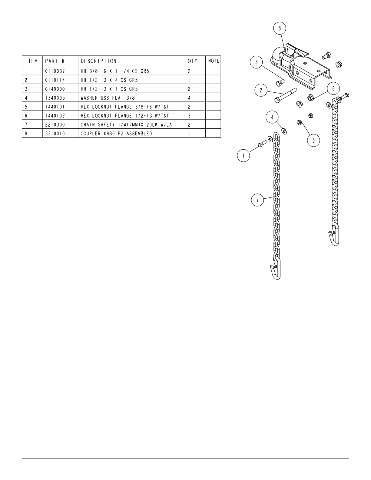
Locate the coupler bag. Place the coupler on the end of the
tongue, align holes and secure with one 1/2” X 4” hex bolts and
hex ange lock nuts in the rear coupler hole. Place two 1/2” X
1” hex bolts into the front holes of the coupler and secure to the
each side of the tongue with 1/2” ange lock nuts. Tighten.
WIRE HARNESS
SAFETY CHAINS
Mount the safety chains to the front of the tongue by placing
a 3/8” at washer onto a 3/8” X 1-1/4” hex bolt, then insert the
bolt through the last link of the safety chain. Put the bolt through
the hole on one side of the tongue as shown. Place on another
at washer and secure with a 3/8” hex ange nut. Tighten. Repeat on the other chain on the other side of the tongue.
WINCH POST
Place t he winc h pos t assembly on the tong ue and secur e
wi th three 3/8” X 4 ” hex b ol ts and hex flange l oc k nu ts.
Place the nuts on the bolts but do not tighten because they
will have to be readjusted once the boat is on the trailer.
Locate the wire harness. Push the two triangular plugs in the hole
on the top of the tongue, then out the rear of the tongue. Place
the wire harness through the hole in the tongue cover plate.
(See Detail A) Secure the tongue cover plate in position with a 1/2”
Remove the winch handle nut from the shaft. Align the hole in the
winch handle with the at surfaces on the shaft. Slide in position and
secure with the nut just removed. Tighten.
X 1-1/2” hex bolt and 1/2” lock nut. Tighten. Plug the tongue wire
harness ends into the frame harnesses by matching colors and ends.
Push the extra wire into the rear of the tongue or remove the grommets in the side frame and place the extra wire in the side frame.
Replace grommets just removed.
Midwest Industries, Inc. Ida Grove, IA 51445 800.859.3028 www.shorelandr.com 0003697
Page 4 11/01/06
Page 5

Midwest Industries, Inc. Ida Grove, IA 51445 800.859.3028 www.shorelandr.com 0003697
Page 5 11/01/06
Page 6

Midwest Industries, Inc. Ida Grove, IA 51445 800.859.3028 www.shorelandr.com 0003697
Page 6 11/01/06
Page 7

Midwest Industries, Inc. Ida Grove, IA 51445 800.859.3028 www.shorelandr.com 0003697
Page 7 11/01/06
Page 8

SPRINGS
Positions the axle so that it is aligned with the trailer.
Place the springs on the top side of the spring pads welded to
the axle. The hook end of the spring must be mounted to the rear
of the trailer. Place a spring clamp on the top center of the spring.
Place the 1/2” X 6-1/2” U-bolts over the top of the spring clamp,
spring and axle. Place the spring and axle U-bolt plate onto the
ends of the two U-bolts. Secure in place with 1/2” lock nuts. Tighten.
AXLE
Place a spring bracket bushing (Item #6) into the rear of the spring
bracket and secure with a 9/16” x 3-1/4” hex bolt and hex lock nut.
Repeat in the other spring bracket. Position the axle under the frame,
hook the hook loop of the spring around the bushings just installed.
Note: If the axle is positioned too low, the hooks will not hook around the
bushings.
Raise the front of the springs up so they align with the front hole of
the spring bracket. Secure in place with 9/16” X 3-1/4” hex bolts and
lock nuts. Tighten all axle U-bolts and spring bolts.
TIRE & WHEEL ASSEMBLY
Mount the tire and wheel assemblies using the 1/2” ne threaded tapered lug nuts provided. Tighten to 85-95 ft./lb. of torque using the rotation pattern as shown in the ShoreLandr’s Owners Manual.
Tire Size and Carrying Capacity Chart
Tire Size ............................ST185/80R 13-C
GVWR ...............................2200 lb.
Carrying Capacity ............1480 lb.
Axle ...................................Non-Brake
Refer to the tire side wall for correct tire pressure.
NOTE: Brakes available as optional equipment.
Recommended carrying capacity is based on shipping weight
of the trailer with standard equipment. Adding optional equip-
ment may decrease the trailer’s carrying capacity.
Re-torque the lug nuts after 50 miles of dri ving and then
periodically thereafter.
Midwest Industries, Inc. Ida Grove, IA 51445 800.859.3028 www.shorelandr.com 0003697
Page 8 11/01/06
Page 9

Midwest Industries, Inc. Ida Grove, IA 51445 800.859.3028 www.shorelandr.com 0003697
Page 9 11/01/06
Page 10

ROLLER ASSEMBLY
Place the roller arm assembly mounting channel over the rear cross
member and secure with a 1/2” x 4-1/4” carriage bolt and lock nut.
Repeat on the other roller arm assembly. The roller arm assembly
should be left loose until the boat is placed on the trailer for adjust-
ment. Once the correct position is determined, tighten.
Midwest Industries, Inc. Ida Grove, IA 51445 800.859.3028 www.shorelandr.com 0003697
Page 10 11/01/06
Page 11

TRAILER ADJUSTMENTS
Axle Adjustment
The amount of tongue weight on your trailer can be adjusted as
follows: To lower the tongue weight, adjust the axle assembly
forward. To increase the tongue weight, adjust the axle assembly
backward. The distance that the axle assembly has to be moved will
vary because it is directly related to the weight and center of gravity
of the boat placed on it. Best towing is achieved when the tongue
weight is 5-7% of the total gross load of the complete unit.
NOTE: The wire harness will need care when moving the
assembly.
Rear Support System
Place the boat on the trailer. The center of the rear rollers
on the roller rack should be approximately 4” from the transom. This gives you maximum support on the transom.
Rollers
Position the roller racks so they are far enough apart to give
your boat stability while transporting. When the desired width is
achieved, move the roller rack system so that the rollers are just
to the outside of the strake. The rollers need to be adjusted so
that you have a minimum of 1” to 2” of clearance between the
kee l of th e bo at a nd t he c ros s me mbe r pa d. Thi s wi ll
help center the boat when loading and unloading.
When the desired position is determined, tighten only enough to hold
the rollers from moving while the other adjustments are being made.
Final tightening will be done at the end of the adjusting process.
Front Support System
Roller
The keel of the boat must rest on the front keel roller system
creating a th ree-point support s ystem. The kee l roller system is designed to fit most boats without further adjustment,
howev er the re is co nsi derab le diffe rence be twe en bo at
b o ttom d e s i g n s and certain l i n e s of b oats w i l l requi re th e fr o nt c r oss mem b er t o be a dju s ted u p fr om
its normal shipping position which is the down position.
Determine how high the front cross member will have to be raised to
t the boat. Note that the front cross member can be adjusted in four
different heights ranging from its down position to a position where
the cross member is at. Loosen the two 3/8” X 5” carriage bolts
located at the outer end of the channels of the front roller assembly.
(See Page 5) Remove the two 3/8” X 3” carriage bolts attaching
the center support channel to the front cross member. Raise the
complete assembly up. Align the desired holes in the cen-
ter supp ort channel with the holes in the cross frame. Re-
insert the two bolts just remov ed. Place o n the lock nut s
removed. Tighten. Tighten the nuts again on the two bolts loos-
ened at the ends of the channels of the front roller assembly.
Adjustment is complete.
Winch Post Adjustment
Slide the winch post assembly back towards the boat. The bow stop
roller needs to be located directly above the boat bow eye to prevent
your boat from moving froward in the event of a sudden stop.
Note that the outer winch base has several holes of adjustment.
Changing the bolt location will change the angle of the winch post
and will raise or lower the height of the bow roller. Choose the
bolt location which best matches it to the bow eye height.
Th e i nn er and ou te r w in ch post cha nnels can telesc op e
either in or out with res pe ct to eac h other t o lengthe n or
shorten the overall length of the post. Loosen the two bolts
located on the back, inside of the channels. Attach the winch
strap into the b ow eye and cran k the winch stra p in unti l
the bow eye is located in it’s proper position just above the
bow eye. Slide the inner post in or out to a desired length.
Once the bow stop roller is located in it’s proper position above the
bow eye, tighten the bolts that secure the assembly to the tongue.
Attach the bow eye safety c hain into the bow eye as well.
This is another level of protection to keep your trailer and
bo at toge th er as o ne unit . It may be used t o keep yo ur
boat on the trailer while loading and unloading at the ramp,
especially with a roller trailer.
Adjustments are now complete. Double check your boat
for t. If desired t has been achieved, tighten all fasten-
ers that may have either been left l oose or have been
loosened to do the adjusting.
See y o ur S h o r eLa n d ’ r O w n e r ’ s G u i d e f o r f u r t her
tec hni cal in for mat ion re gar din g your tra ile r and i ts
components.
Midwest Industries, Inc. Ida Grove, IA 51445 800.859.3028 www.shorelandr.com 0003697
Page 11 11/01/06
Page 12

Midwest Industries, Inc. Ida Grove, IA 51445 800.859.3028 www.shorelandr.com 0003697
Page 12 11/01/06
 Loading...