

Page 1
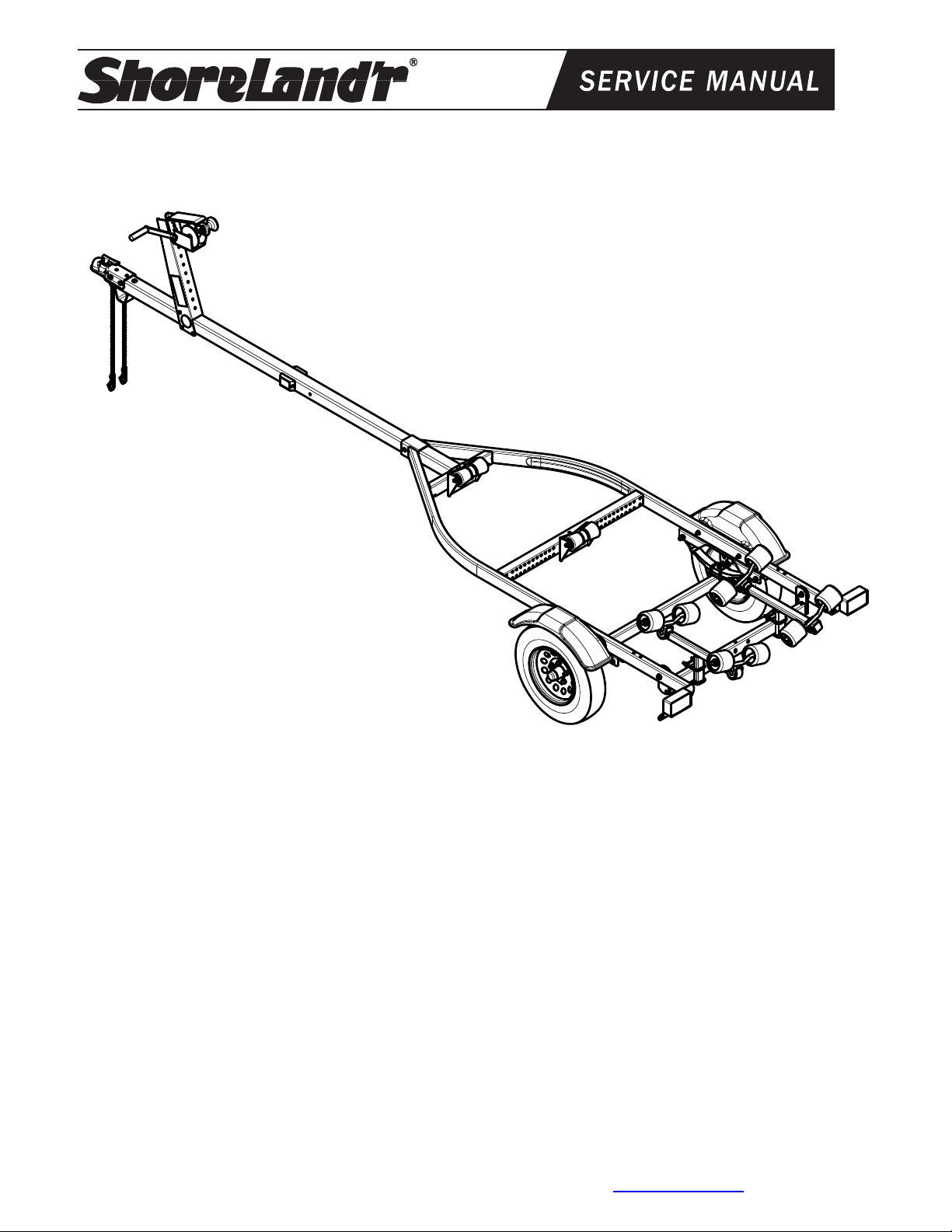
SLR10TS__, SLR10TM__, & SLR10TL__
SLR10TS, SLR10TM, SLR10TL (All Colors) Bundles Required:
* 4.80 X 12-B Tire/TSilver Mod Rim .............2
62340 Literature Bag - Trailers ..............................1
80152-- Frame Bundle - 44” Roller Bundle ..............1
65780-- Tongue 3X3X14 GA X 7’ ............................1
or
65537-- Tongue 3X3X14 GA X 8’ 6” ........................1
or
65516-- Tongue 3X3X14 GA X 10’ ..........................1
68758-- Hardware Box 44” Roller ............................1
60163-- Axle Assembly - Tadpull .............................1
ShoreLand’r offers their product line a painted finish. When
ordering parts it is important that you specify the finish or
color you have on your product. The five (5) digit number
along with a two (2) digit space _ _, note the parts which
can be purchased with various finishes. When ordering
these items use the five (5) digit number along with a two
(2) digit suffix for the proper finish.
00 .........Galvanized
03 .........Black
Midwest Industries, Inc. Ida Grove, IA 51445 800-859-3028 www.shorelandr.com 0003276
Page 1 of 9 Rev B 4/15/2011
Page 2
Midwest Industries, Inc. Ida Grove, IA 51445 800-859-3028 www.shorelandr.com 0003276
Page 2 of 9 Rev B 4/15/2011
Page 3
Midwest Industries, Inc. Ida Grove, IA 51445 800-859-3028 www.shorelandr.com 0003276
Page 3 of 9 Rev B 4/15/2011
Page 4

Recommended carrying capacity is based on
shipping weight of the trailer with standard
equipment. Adding optional equipment may
decrease the trailer’s carrying capacity.
Tire Size and Carrying Capacity Chart
Tire Size 4.80 X 12-B
GVWR 1495 lb.
Carrying Capacity 1000 lb.
Axle Standard (Non-Brake)
Refer to the tire side wall for correct tire pressure.
Midwest Industries, Inc. Ida Grove, IA 51445 800-859-3028 www.shorelandr.com 0003276
Page 4 of 9 Rev B 4/15/2011
Page 5

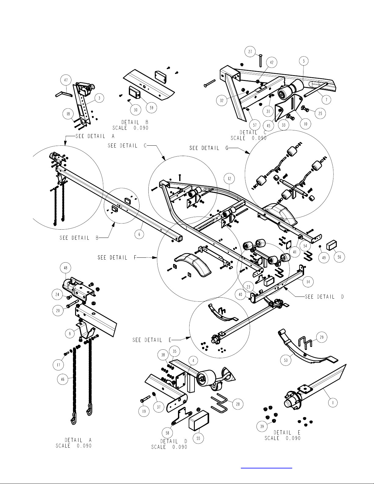
WINCH POST ASSEMBLY
The winch post assembly is pre-assembled and is
shipped banded to the frame. See Diagram C. Place the
winch post on the tongue in the approximate location.
Attach to the tongue using three (3) 3/8” x 4” hex bolts
and 3/8” flange lock nuts. It can be left loose until the
boat is placed on the trailer for final adjustment.
Place the winch handle on the drive shaft of the winch by
mating the flat sides of the drive shaft with the punched
hole in the winch handle. Secure the handle to the drive
shaft with the 1/2” lock nut provided. Tighten
Midwest Industries, Inc. Ida Grove, IA 51445 800-859-3028 www.shorelandr.com 0003276
Page 5 of 9 Rev B 4/15/2011
Page 6

Midwest Industries, Inc. Ida Grove, IA 51445 800-859-3028 www.shorelandr.com 0003276
Page 6 of 9 Rev B 4/15/2011
Page 7

Repeat this process on the other side of the tongue. On ce
TONGUE ASSEMBLY
Place the frame to be assembled on saw horses or stands to
assist in the assembly. Remove all items that are banded to
the frame. Sort the items in the hardware box by item and the
hardware by size.
Locate the tongue for the trailer. Note that there are three
different lengths of tongues designed to fit this particular
frame. The length of tongue will determine the length of boat
that can be placed on the trailer when assembled. The 7 foot
tongue will accommodate boats up to 12 feet in length, the 8’6” tongue will fit boats 12-14 feet in length and the 10 foot
tongue is used for boats 14-16 feet long. See Diagram B.
Once the proper tongue is identified place it on the stands so
it can be prepared for installation into the frame. Locate t he
two amber side marker lights shipped in the hardware box.
Uncoil the wire and insert the plug end into the larg er, center
hole that is drilled in the side of the tongue. As the wire is
inserted into the hole direct the wire so that it will go to the
forward end of the tongue. Pull the wire out the front of the
tongue. It will be connected to the tongue harness at a later
time. Attach the light to the tongue using two (2) No. 10 x 3/4”
self-tapping screws provided. Repeat this process on the
other light on the other side of the tongue.
Locate the tongue wire harness. Insert the end of the harness
with the small plug into the hole located in the top of the
tongue. Pull the wire backward through the tongue until the
end comes out the rear of the tongue. As the wire harness is
inserted note that there are two single bullet wires towards
the front plug of the tongue wire harness. Pull these wires
forward as the wire harness is inserted into the tongue. Plug
the single wires from the side marker lights installed earlier
into the two single bullets of the tongue harness. Push the
additional back into the front of the tongue to keep it from
damage during use. Place a rubber grommet around the wire
harness and in the hole in the top of the tongue to protect the
wires from damage during use.
Route the harness plug at the rear of the tongue through the
hole provided in the side of the tongue. Pull both the plug a nd
the white ground wire out the hole. They will be attached later
once the tongue is installed in the frame.
Locate the bolt on tongue stand Item No. 1 in Diagram B.
Look at the bottom side of the tongue and locate the slotted
key slot hole in the tongue. Note that one end of the tongue
stand has a dart or arrow shaped end. With the tongue stand
positioned 90 degrees to the centerline of the tongu e, insert
the dart or arrow end of the tongue stand into the key slotted
hole. Once it is inserted, turn the tongue stand 90 degrees so
that it now is in line with the centerline of the tongue. Attach
the front end of the tongue stand to the tongue using a 1/2”
x1” hex bolt and flange lock nut. Tighten.
Locate the safety chains. Place a 3/8” flat washer on a 3/8” x
1” hex bolt. Insert the bolt through the last link in the safety
chain and then into the lower hole provided in the front of the
tongue. Secure with a 3/8” flange lock nut. Tighten. on the
the bolts are installed, tighten all nuts left loose at this time.
Insert the tongue assembly through the front channel of the
frame far enough so the rear of the tongue is inserted into
the front cross member. Align the cross hole in the front
channel and the tongue and insert a 3/8” x 4” hex bolt.
Secure with a 3/8” flange lock nut. Place a second 3/8” x 4”
hex bolt down through the hole in the rear of the tongue and
the front cross member. Place on a 3/8” flange lock nut.
Tighten.
Connect the tongue wire harness into the side frame
harness of the trailer by matching plugs. Attach the white
ground wire of the tongue harness to the frame using a No.
10 x 3/4” self-tapping screw provided so that a good ground
connection is made between the frame of the trailer and the
tow vehicle. Push all extra wires used to make the
connection back into the tongue. Place a second rubber
grommet into the hole where the wires exit the tongue to
protect them from damage during normal use.
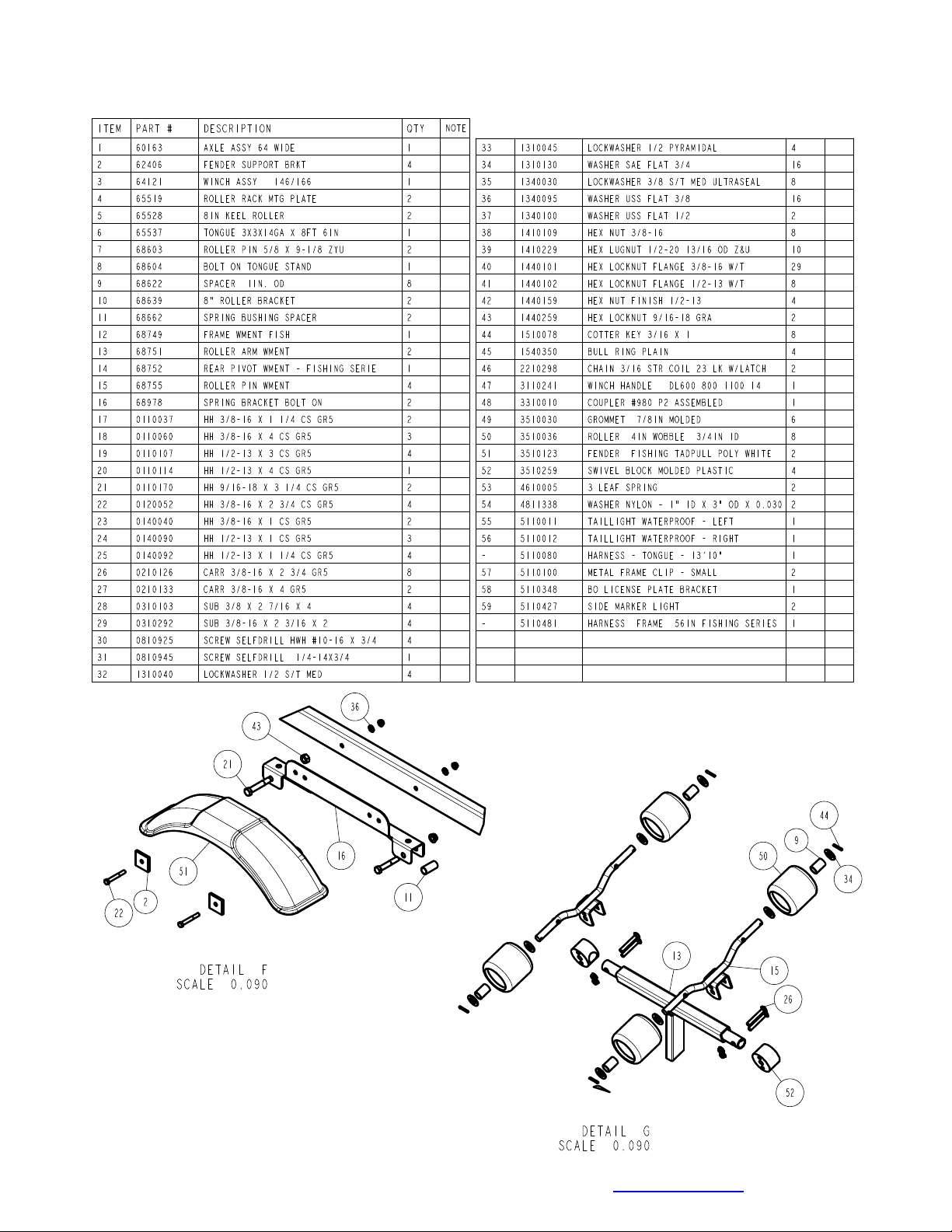
REAR ROLLER RACKS
Locate the swivel block molded plastic pieces. Slide them
onto the ends of the roller arm weldment as shown. Place
the channel bracket of the roller pin assembly down over the
plastic pieces and secure them together with two (2) 3/8” x
2-3/4” carriage bolts and 3/8” flange lock nuts. Note that one
bolt will be on the top side of the metal tube while the other
will be installed so the bolt passes through the large hole in
the metal tube. This will allow the roller assemblies to rotate
on the roller arm weldment to conform to the boat bottom
and still support the load applied to it when the boat if
carried on the trailer. Tighten. Repeat this process on the
other roller arm weldment.
Loosen the two bolts that attach the rear pivot to the tra iler
side frames and rotate the rear pivot from it ship position
down into its normal position. Locate the roller rack
mounting plates. Place two of the 3/8” x 2-7/16” x 4” U-bolts
into the holes of the plate as shown and thread on 3/8”
flange lock nuts.
Slide the plate with U-bolts just installed onto the rear pivot
so that the roller rack mounting plate is to the front side of
the rear pivot with one U-bolt above the rear pivot and one
is below the rear pivot cross member. Push the U-bolts
rearward creating all of the spacing between the inside of
the U-bolts and the back side of the rear pivot cross
member. Orient one of the roller arm assemblies so that the
roller pin assemblies tip inward towards the centerline of the
trailer. Drop the mounting tube of the roller arm weldment
down inside the U-bolts and behind the rear pivot cross
member. Adjust the roller arm assemblies up to the desired
height to carry your boat properly and tighten the U-bolts.
Assembly is complete.
Midwest Industries, Inc. Ida Grove, IA 51445 800-859-3028 www.shorelandr.com 0003276
Page 7 of 9 Rev B 4/15/2011
Page 8

KEEL ROLLER INSTALLATION
Remove the keel roller assemblies from the hardware bo x.
Position them on the back side of the front two cross
members of the frame as shown in Diagram A. Attach them
to the cross members by placing a 1/2” star washer on a
1/2” x 1-1/4” hex bolt. Align the slot in the keel roller bracket
with the hole provided in the cross member. Insert the bolt
into the slot, then into the hole in the cross member and
attach to the cross member with a 1/2” lock washer and hex
nut. Repeat this process on the second bolt used to attach
the keel roller assembly to the cross member.
Repeat the above process on the second keel roller
assembly. The keel roller assemblies can be left loose until
the boat is placed on the trailer for final adjustment.
AXLE & WHEEL ASSEMBLY
Locate the axle for the trailer. Note that there isn’t a right or
left to the axle assembly. Place one of the springs on top of
the spring pad welded to the axle as shown in Diagram D.
Drop two (2) 3/8” x 2 3/16” x 2” U-bolts over the springs and
down through the holes in the spring pad. Secure with 3/8”
flange lock nuts. Repeat this process on the other spring
mounting it so that it is oriented on the a xle the same as th e
first spring.
Slip a spring bushing spacer into the rear of the spring
bracket, align the bushing with the hole in the bracket and
secure in position using a 1/2” x 3” hex bolt and 1/2” flange
lock nut. Tighten. Repeat on the other spring bracket.
Slide the axle assembly under the trailer frame, raise up and
slide the rear of the springs above the bushings just
installed. Rotate the assembly up until the front spring eyes
align with the front holes in the spring bracket. Insert a 9/16”
x 3-1/4” hex bolt and secure with a 9/16” lock nut. T ighten.
Tighten the U-bolt attaching the springs to the axles at this
time and any other bolts that may have been left loose for
ease of assembly.
Place the tire and wheel assemblies on the hubs and secure
with the 1/2” tapered lock nuts.
TIRE & WHEEL ASSEMBLIES
Mount the tire and wheel assemblies using the 1/2” fine
threaded tapered lug nuts provided. Tighten to 80-90 ft/lb. of
torque using the rotation pattern as shown in the
ShoreLandr’s Owners Manual. Re-torque the lug nuts
after 50 miles of driving and then periodically thereafter.
TRAILER ADJUSTMENTS
Place the boat on the trailer so that the center of t he rear
rollers on the roller rack are approximately 4” from the
transom of the boat.
Check the boat for clearance with the fenders and tongue.
Enough clearance is required between the two so that the
boat does not contact the frame during loading and
unloading.
REAR ROLLER RACK
The spacing between the rollers on the roller rack can be
changed so that they will adapt to the spacing of the boat
strakes. To change the spacing remove the cotter key that
holds the roller to the roller pin. Remove the washers and
roller. Note that there is a spacer on the roller pin. This
spacer can be installed either to the inside of outside of the
roller. Depending where it is placed will change the spac ing
with regards to the roller on the other end of the roller pin.
The roller and spacer on the other end of the pin can be
interchanged as well if needed. As a result the spacing can
be changed either 1-1/2” or 3” between the rollers. Once
installed in the proper location to fit your boat, reinstall the
roller and washers. Secure in place with the cotter key just
removed.
The height of the roller rack with respect to the frame can be
changed. Loosen the U-bolts attaching the roller arm
assemblies to the rear pivot arm. Raise or lower the roller
arm assemblies to the desired height, then retighten the Ubolts securing the roller rack assemblies in the new location.
The roller rack spacing between the individual racks can be
changed by sliding the roller arm assemblies to the desired
location before tightening the U-bolts attaching them to the
rear pivot arm.
Note that they must be spaced the same distance out ward
from the center line of the trailer for the boat to load straight.
KEEL ROLLERS
Check the front of the boat for clearance between the frame
and tongue. The keel rollers have slotted holes so they can
be adjusted up or down to raise or lower your boat. Position
your boat as desired on the trailer. Loosen the bolts and
nuts attaching the keel rollers to the cross members. Raise
the keel roller assemblies up against the keel of the boat .
Retighten in the new location. Note that the boat will settle
into the keel rollers a little during normal use so it may be
necessary to adjust them slightly higher to compensate for
this.
WINCH POST
Once the boat is in the desired location and correct height
on the trailer the winch post can now be adjusted.
Slide the winch post on the tongue until it contacts the boat.
Note that the V-block on the winch post must be positioned
directly above the boat bow eye. This location is necessary
to prevent the boat from sliding forward during normal use
as well as in the event of a sudden stop. This positioning will
also allow the winch strap to pull directly from the winch into
the bow eye for better retention. Change the bow stop
height by removing the bolts attaching it to the winch post.
Relocate to the proper height and refasten with the bolts just
removed. Note that the winch may have to be moved as
well to accomplish the height change.
Midwest Industries, Inc. Ida Grove, IA 51445 800-859-3028 www.shorelandr.com 0003276
Page 8 of 9 Rev B 4/15/2011
Page 9

Once the winch post is set secure the winch post to the tongue
with the three mounting bolts used to attach it to the tongue.
The axle is not adjustable on this model trail er. To change the
tongue will require you to place the addition al gear in the boat
in the correct location. Moving the added weight forward or
backward will change the tongue weight.
A recommended tongue weight for your trailer is 7-10% of the
total load including boat, motor, and trailer.
Adjustments are now complete. Double check your boat for fit.
If desired fit has been achieved, tighten all fasteners that may
have either been left loose or have been loosened to do the
adjusting.
Note: All nuts and bolts must be tightened before towing.
The law requires that the white ground wire on both the tongue
wire harness and vehicle harness be properly grounded to
respective trailer and vehicle frames.
Re-check all fasteners on the complete trailer to make sure
they are all tight and ready for towing. All fasteners shoul d be
periodically check before towing.
See your ShoreLand’r Owner’s Guide for further technical
information regarding your trailer and its components.
Midwest Industries, Inc. Ida Grove, IA 51445 800-859-3028 www.shorelandr.com 0003276
Page 9 of 9 Rev B 4/15/2011
 Loading...