

Page 1
®
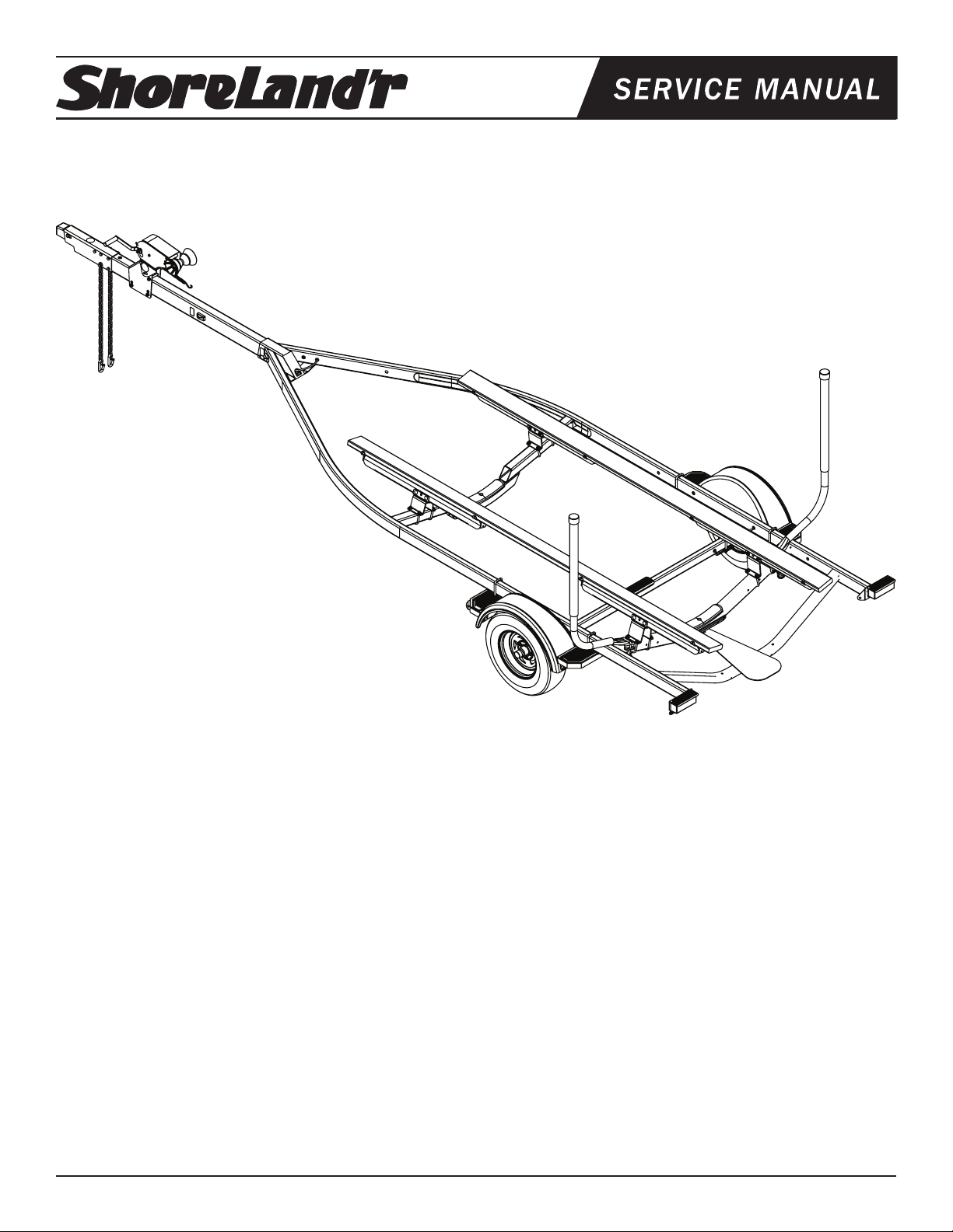
SLIB29B-00 & SLIB29B-03
2x4x74 Inboard Trailer
SLIB29B-00
69082 Lit Packet - Brake Trailers
4300198 ST215/75R14-C GY Galv Dir Rim
6643800 Axle Assembly w/Brakes 2x4x74W
8055700 Frame Bundle - Inboard Single
Midwest Industries, Inc. Ida Grove, IA 51445 800.859.3028 www.shorelandr.com 0003800
Page 1 05/01/07
SLIB29B-03
69082 Lit Packet - Brake Trailers
4300199 ST215/75R14-C GY TSilver Dir Rim
6643803 Axle Assembly w/Brakes 2x4x74W
8055703 Frame Bundle - Inboard Single
Page 2
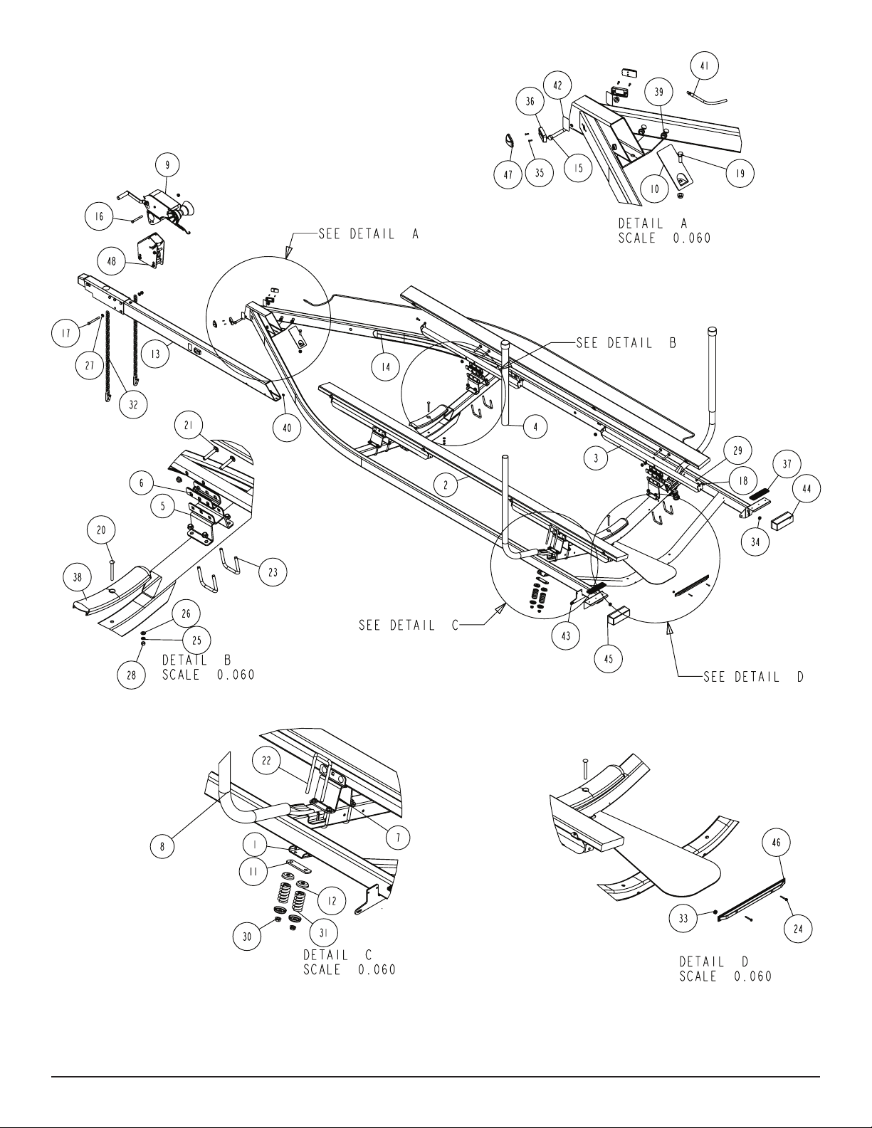
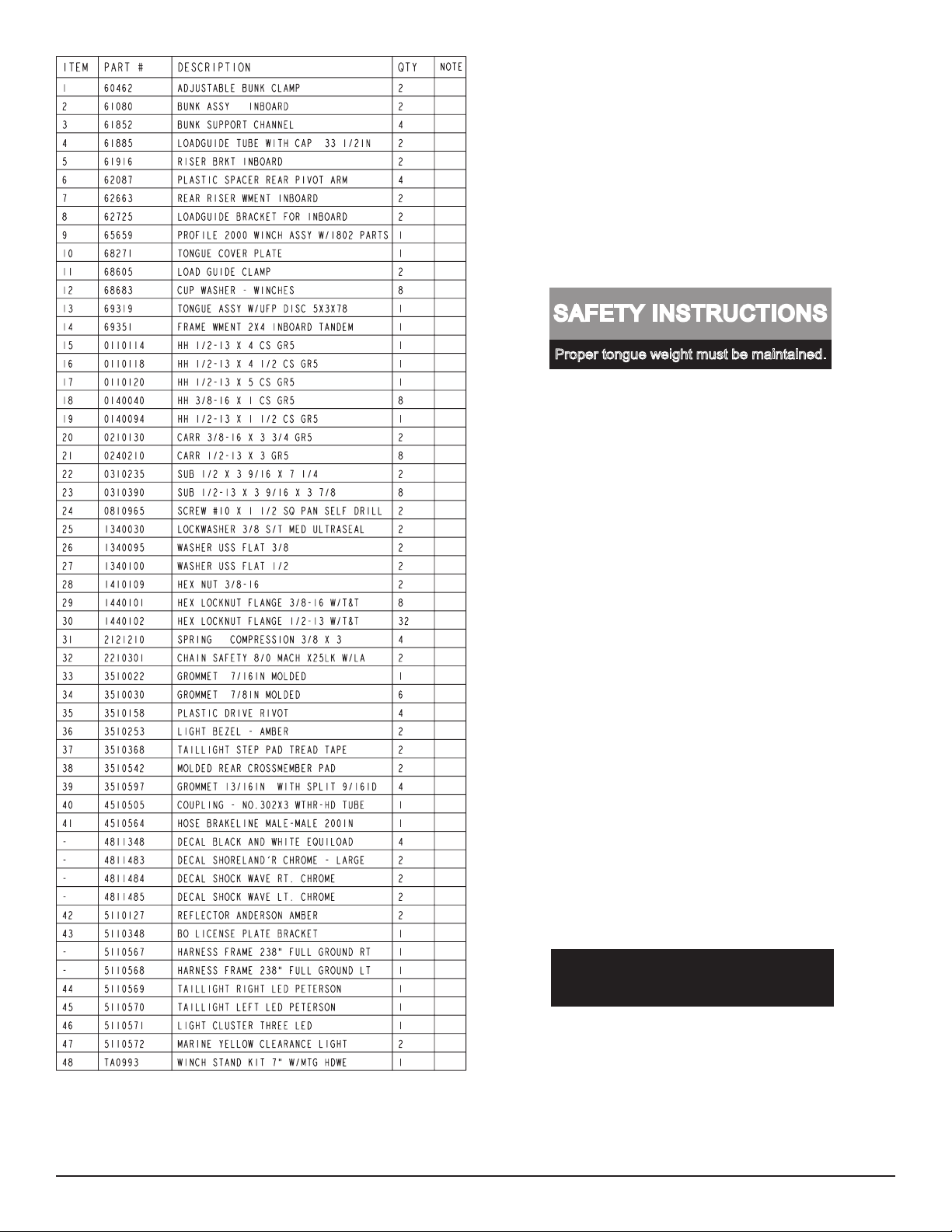
Diagram A
Midwest Industries, Inc. Ida Grove, IA 51445 800.859.3028 www.shorelandr.com 0003800
Page 2 05/01/07
Page 3
Refer to your ShoreLand’r Owner’s
Guide and other decals on trailer for
additional information.
SAFETY INSTRUCTIONS
4810709
Proper tongue weight must be maintained.
Rev C 8/28/06
Before towing, check the following to ensure
that:
1. All parts, bolts, nuts and wheel lug
nuts are tight.
2. All wheel lug nuts must be tightened
to a minimum torque rating of 85 ft/lb.
3. Lug nuts must be re-torqued after the
first 50 miles, then periodically there
after.
4. Tires are inflated to manufacturer’s
standards. (See tire sidewall)
5. Wheel bearings have adequate
grease.
6. Hitch ball is the proper diameter and
has a rating equal to or greater than
the GVWR of the trailer.
7. Coupler is properly attached and
secured to coupler ball.
8. Trailer safety chains are crossed
under the tongue and attached to
towing vehicle.
9. All lights are operational. Note: It is
recommended that the trailer lights
be disconnected before backing into
the water.
10. Tie downs, winch strap and bow eye safety chain are secure.
11. Trailer tongue jack is in up or travel
position.
ShoreLand’r offers their product line a painted nish. When ordering
parts it is important that you specify the nish or color you have on
your product. The ve (5) digit number along with a two (2) digit space
_ _, note the parts which can be purchased with various nishes.
When ordering these items use the ve (5) digit number along with
a two (2) digit sufx for the proper nish.
00..........Galvanized
03..........Black
FINAL ASSEMBLY INSTRUCTIONS
Remove all banded items and the hardware bag from the frame.
Remove the parts and sort by size.
Midwest Industries, Inc. Ida Grove, IA 51445 800.859.3028 www.shorelandr.com 0003800
Page 3 05/01/07
Page 4
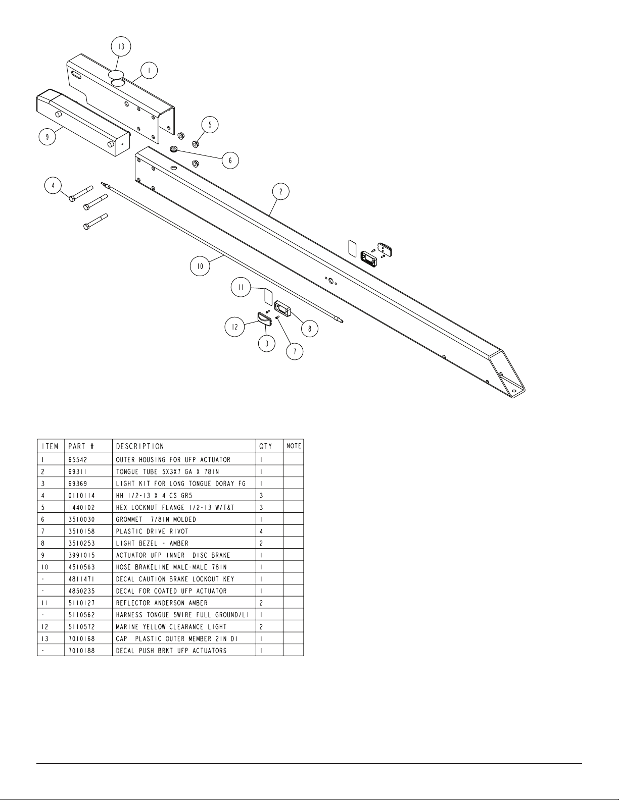
TONGUE
Locate the tongue and install by sliding it in the front of the tongue
channel.
Line the holes in the tongue with the holes in the tongue channel.
Install the 1/2” x 4” hex bolt in the front cross hole and secure with
a 1/2” ange lock nut.
Remove the wire harness from the rear of the tongue. Place the
wire harness and the brake hose through the hole provided in the
tongue cover plate.
Secure the tongue cover plate in position with the same 1/2” x 11/2” hex bolt that secures the back on the tongue to the tongue
channel of the frame. Secure with a 1/2” lock nut. Tighten both bolts
just installed.
Diagram B
Plug the tongue wire harness ends into the frame harnesses by
matching colors and ends. Push the extra wire provided into the
rear of the tongue. The wire should be positioned so the only thing
exposed to the outside of the tongue and side frame is the black
wire loom.
TONGUE BRAKE HOSE CONNECTION
Locate the brass brake line coupling. Remove the plastic cap from
the tting on the end of the tongue hose. Thread into one end of the
coupling. Remove the hose from the side frame enough to reach
into the rear of the tongue. Remove the plastic cap from the tting
on the side frame hose, then thread into the other end of the coupling. Tighten.
Push the excess hose back inside the tongue so that the coupling
just installed is located inside the rear of the tongue.
Midwest Industries, Inc. Ida Grove, IA 51445 800.859.3028 www.shorelandr.com 0003800
Page 4 05/01/07
Page 5

Diagram C
SAFETY CHAINS
Locate the 1/2” x 5” hex bolt. Slip the bolt through a 1/2” at washer,
then place through the last link of one of the safety chains.
Place the bolt with chain attached through the hole provided in the
bottom front of the actuator mount on the tongue. Place the second
chain on the portion of the bolt extending through the other side
of the tongue. Place on another 1/2” at washer and hex lock nut.
Tighten.
Place the inside jack spacer on the winch base so the center pro-
trusion ts down into the indent in the winch base.
WINCH POST INSTALLATION
The height that the bow eye is placed in your boat will determine
the length winch post required. Once this is determined, attach the
winch base to the tongue with three 1/2” x 4-1/2” carriage bolts and
lock nuts.
Align the holes in the Prole 2000 mounting channel with the holes
in the top of the winch base. Attach the front of the winch head
mounting channel to the base by placing a 1/2” x 4-1/2” hex bolt
through the hole closest to the front of the winch base. Secure with
a lock nut. Do not tighten.
Note that the winch head can now be rotated either up or down.
Identify the correct hole combination to use to position the bow eye
roller just above the bow eye of your boat. When determined, secure in this position by placing the bushing as shown in Diagram D
inside the winch base so it aligns with the hole just identied for the
proper adjustment. Insert another 1/2” x 4-1/2” hex bolt through the
determined mounting hole in the mounting channel and winch base
making sure the bolt passes through the bushing as well. Secure
with a 1/2” lock nut. Tighten all bolts.
Midwest Industries, Inc. Ida Grove, IA 51445 800.859.3028 www.shorelandr.com 0003800
Page 5 05/01/07
Page 6

Midwest Industries, Inc. Ida Grove, IA 51445 800.859.3028 www.shorelandr.com 0003800
Page 6 05/01/07
Page 7

Diagram D
Midwest Industries, Inc. Ida Grove, IA 51445 800.859.3028 www.shorelandr.com 0003800
Page 7 05/01/07
Page 8

Disc Brake Axle
Midwest Industries, Inc. Ida Grove, IA 51445 800.859.3028 www.shorelandr.com 0003800
Page 8 05/01/07
Page 9

Tire Size and Carrying Capacity Chart
Tire Size ............................ST215/75R 14-C
GVWR ...............................3740 lb.
Carrying Capacity ............2900 lb.
Axle ...................................Brake
Refer to the tire side wall for correct tire pressure.
Recommended carrying capacity is based on shipping weight
of the trailer with standard equipment. Adding optional equipment may decrease the trailer’s carrying capacity.
SPRINGS
Position the axle so it is properly aligned with the trailer. The end of
the axle that has the brake line hose attached must be to the right
side of the trailer when standing at the rear of the trailer and looking forward. This positioning places the disc brake calipers on the
backside of the axle.
Place the springs on the topside of the spring pads welded to the
axle. (See Diagram D). Note that the hook end of the spring must be
mounted to the rear of the trailer. Place a spring clamp on the top
center of the spring as shown. Next place the 1/2” x 6-1/2” U-bolts
down over the top of the spring clamp, spring and axle as shown.
Place the spring and axle U-bolt plate onto the ends of the two Ubolts just placed around the axle. Secure with 1/2” lock nuts. Thread
onto the U-bolts but do not tighten securely until the complete unit
is in position on the trailer. Repeat on the other spring.
AXLE
Place one of the spring bracket bushings into the rear of the spring
bracket and secure with a 9/16” x 3-1/4” hex bolt and hex lock nut.
Repeat in other spring bracket.
Position the axle under the frame, then hook the hook loop of the
spring around the bushings just installed. Note that if the axle is
positioned too low when trying to hook, the hooks will not hook
around the bushings.
Raise the front of the springs up so they align with the front hole
of the spring bracket. Secure in place with 9/16” x 3-1/4” hex bolts
and lock nuts.
Tighten all axle U-bolts and spring bolts not tightened at this time.
ONE AXLE BRAKE INSTALLATION
Cut the tape securing the brake line hose to the axle. Remove the brass plug from the port in the brass block on
the right brake caliper. Thread in the brake hose male
end and tighten. Repeat on opposite side of axle.
Carefully pull brake line hose from the side frame tube, threading it
through the brake line clip and down to the port in the brass block
on the right caliper. Remove the plastic cap and thread into the port
on the brass block and tighten. Insert grommet into the brake line
clip to protect hose. All bleeding of the line can be done through the
bleeder on the caliper.
Fill the actuator reservoir with brake fluid and bleed the line per
the instructions in the brake manual. All bleeding to the line can be
done through the bleeders on the left calipers.
ATTACHING THE AXLE HOSE TO THE SPRING PLATE
It is important that the brake hose on each end of the axle be attached to the spring plate to eliminate the loops that are formed in
the hose when it is attached to the calipers. Doing so will eliminate
the possibility of the hose getting caught or damaged while towing.
Locate one of the hose clamps. Spread open the clamp so it can be
slipped around the hose in the loop that is formed under the spring
as it is routed to the caliper. Once in position, squeeze the clamp
back together.
Raise the hose clamp and the loop up until the hose clamp is on top
of the spring bracket raising the loop up so it is on the back side of
the axle. Align the hole in the clamp with the hole in the rear of the
spring bracket between the two U-bolts.
Place a No. 10 flat washer on a No. 10 x 1” machine bolt. Insert the
bolt into the clamp, then down through the spring bracket. Place
another No. 10 flat washer over threaded end of bolt and secure
with a No. 10 hex nut. Tighten.
Repeat this process on the other loop on the other end of the axle.
TIRE & WHEEL ASSEMBLIES
Mount the tire and wheel assemblies using the 1/2” fine threaded
tapered lug nuts provided. Tighten to 85-95 ft/lb. of torque using the
rotation pattern as shown in the ShoreLandr’s Owners Manual.
Re-torque the lug nuts after 50 miles of driving and then periodically thereafter.
Midwest Industries, Inc. Ida Grove, IA 51445 800.859.3028 www.shorelandr.com 0003800
Page 9 05/01/07
Page 10

BUNKS
Locate the bunks. Position one of them so it is above the Equiload
arms on the trailer. Align the holes in the bunk brackets attached to
the bunk with the holes in the ends of the Equiload arms. Secure
with 3/8” X 1” hex bolts and lock nuts. Tighten but do not over tighten because the bunks must be able to rotate enough to conform to
the bottom of the boat.
Repeat on the other bunk.
POST LOAD GUIDES (See Diagram A - Detail C)
Locate the post load guides. Position one of them as shown on
the rear cross member of the trailer frame. Drop a 1/2” X 3-9/16” x
7-1/4” square U-bolt down through the holes in the load guide so
one leg of the U-bolt is on each side of the cross member. Pace on
an adjustable bunk bracket clamp so the legs of the bracket t up
around the cross member. Place on one of the 1-1/2” wide X 5” long
straps over the legs of the U-bolt. Next place a cup washer onto the
U-bolt legs so the cup is down. Place on a 3” compression spring
on each leg of the U-bolt, then a second cup washer on each U-bolt
leg so the cup is up. Secure the parts on the U-bolt legs with 1/2
ange lock nuts. Tighten. Note that the load guide can be slid in out
from the center line of the trailer to accommodate for different width
boats. Adjust for width once the boat is on the trailer.
Repeat the above process on the other load guide.
Midwest Industries, Inc. Ida Grove, IA 51445 800.859.3028 www.shorelandr.com 0003800
Page 10 05/01/07
Page 11

TRAILER ADJUSTMENTS
The adjustment of the trailer to your boat is very important not only
for the trailer, but also the boat. Failure to do so may lead to potential failure or damage to either the trailer or boat.
Adjust as follows:
Axle Adjustment
The amount of tongue weight on your trailer can be adjusted as
follows:
To lower the tongue weight, adjust the axle assembly forward. To
increase the tongue weight, adjust the axle backward.
The distance that the axle assembly has to be moved will vary because it is directly related to the weight and center of gravity of the
boat placed on it.
Winch Post
The winch post is pre-assembled. If it does not t, use the following
instructions to adjust to properly t your boat.
Once all other adjustments are complete the winch post can be adjusted. Slide the winch post base backward on the tongue until the
bow roller comes in contact with the boat. This bow roller needs to
be positioned directly above the boat bow eye to prevent your boat
from moving forward in the event of a sudden stop. It can be moved
up or down by removing the back bolt that mounts the winch head
to the base. When this bolt is removed, the head can be rotated up
or down to reach the desired height required to t your boat. Once
in this position, align the closest pair of holes in the brackets and
reinsert the bolt just removed. Tighten. Attach the winch strap and
crank winch tight. Attach the bow eye safety chain into the bow eye
of the boat as well. This is just another level of protection to keep
your boat and trailer together as one unit.
Best towing is achieved when the tongue weight is 5-7% of the total
gross load of the complete unit.
Wire harnesses and brake line lines will need care when moving
the axle assembly.
Rear Support System
Place the boat on the trailer so that the transom is located at the
rear of the support system. The transom of the boat should be within 1-2” of the end of the bunks.
Bunks
Make sure the bunks are positioned far enough apart to give your
boat as much stability as possible while transporting. Position the
bunks so they are located just to the outside of a strake.
Front Support System
Bunk
Adjust the bunks up so that there is approximately 1-2 inches clearance between the keel of the boat and the center cross member
pad.
Check the boat to make sure it is in the desired location forward
and backward on the trailer. If location is as instructed above, tighten the three bolts in the winch base securing the winch base to the
tongue.
Once all adjustments are complete and checked, connect to the
tow vehicle to make sure all of the lights are operating properly and
match the tow vehicle.
Re-check all fasteners on the complete trailer to make sure they
are all tight and ready for towing. All fasteners should be periodically checked before towing.
See your ShoreLand’r Owner’s Guide for further technical information regarding your trailer and its components.
Recommended carrying capacity is based on shipping
weight of the trailer with standard equipment. Adding
optional equipment may decrease the trailer’s carrying
capacity.
Midwest Industries, Inc. Ida Grove, IA 51445 800.859.3028 www.shorelandr.com 0003800
Page 11 05/01/07
Page 12

Midwest Industries, Inc. Ida Grove, IA 51445 800.859.3028 www.shorelandr.com 0003800
Page 12 05/01/07
 Loading...