

Page 1
®
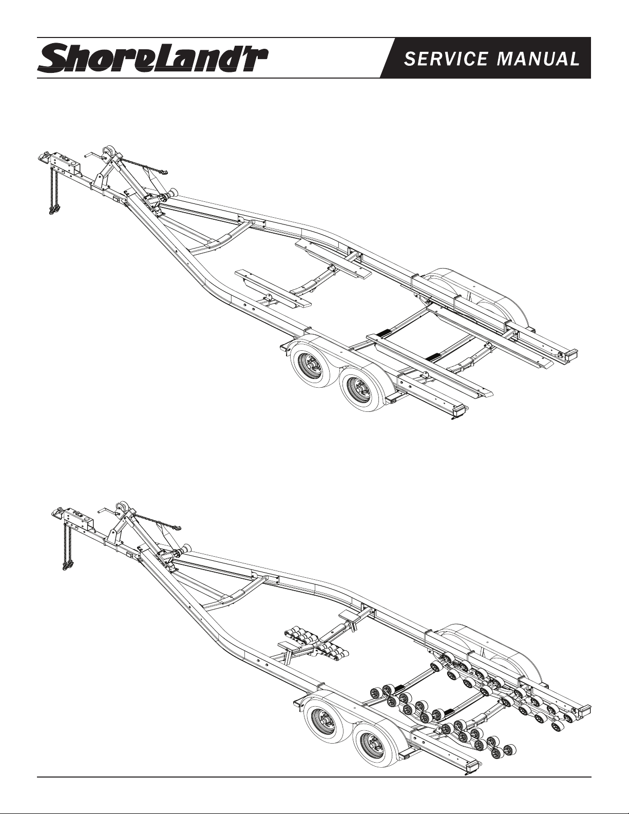
SLB82TAL, SLR82TAL, SLRB82TAL, & SLXR82TAL
Aluminum Trailer - 8200#
SLB82TAL Alum Trailer Bunk
*ST225/75R15D Tire /Galv Dir Rim
4510658 Actuator - 16000# UFP GDC160
69082 Lit Packet Brake Trailers
8065900 Frame Bundle - SLB82TAL
68732 Brake Box Tandem
*Check with your dealer/customer service representative for current tire/rim assembly
part number.
SLR82TAL Alum Trailer Roller
*ST225/75R15D Tire /Galv Dir Rim
4510658 Actuator - 16000# UFP GDC160
69082 Lit Packet Brake Trailers
8066000 Frame Bundle - SLR82TAL
68732 Brake Box Tandem
*Check with your dealer/customer service representative for current tire/rim assembly
part number.
Tire Size and Carrying Capacity Chart
Tire Size ............................ST225/75R15D
GVWR ...............................9,990 lb.
Carrying Capacity ............8,200 lb.
Axle ...................................Tandem Axle - Disc Brakes
Refer to the tire side wall for correct tire pressure.
Midwest Industries, Inc. Ida Grove, IA 51445 800.859.3028 www.shorelandr.com 0004016
Page 1 Rev A 11/18/2008
Page 2
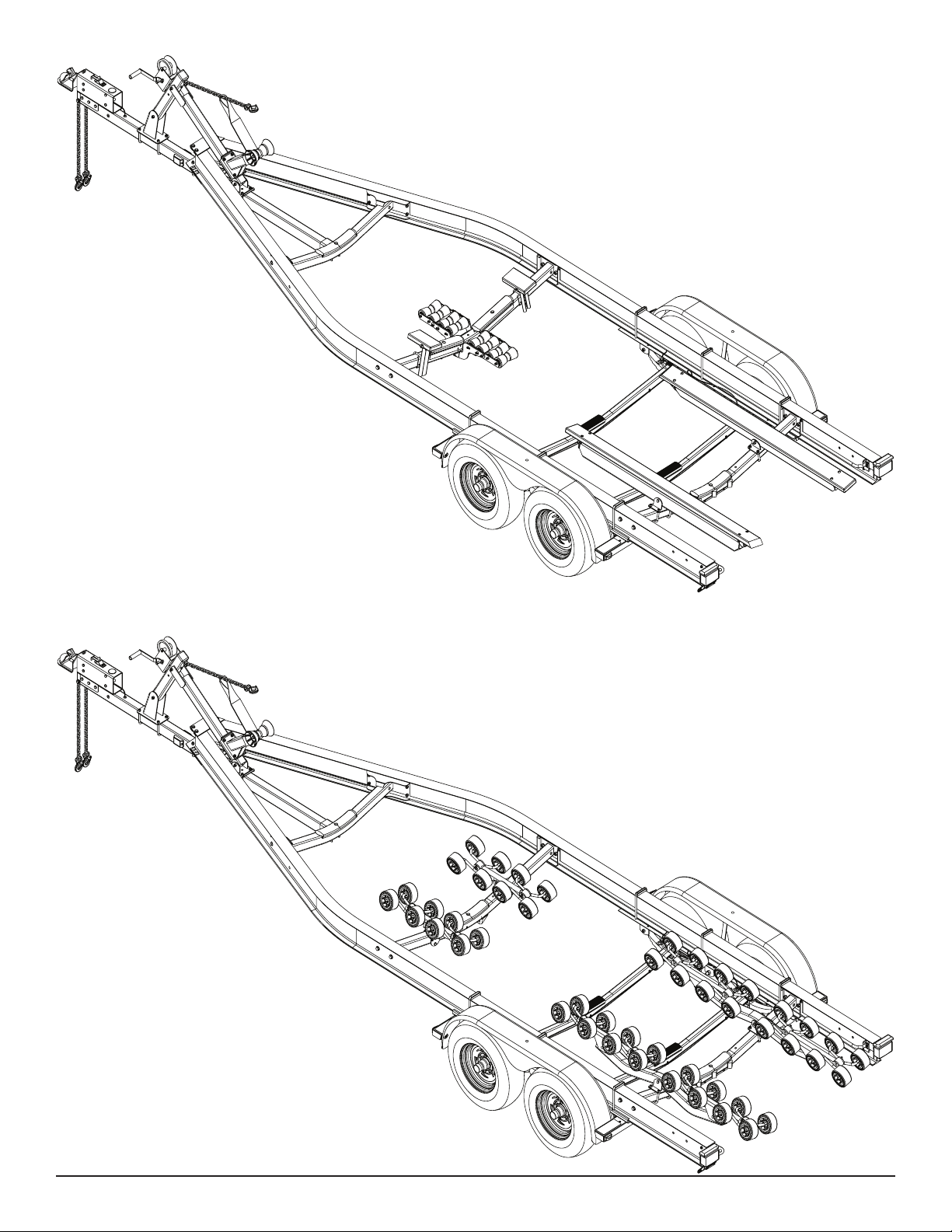
SLRB82TAL Alum Trailer Roller Bunk
*ST225/75R15D Tire /Galv Dir Rim
4510658 Actuator - 16000# UFP GDC160
69082 Lit Packet Brake Trailers
8066200 Frame Bundle - SLRB82TAL
68732 Brake Box Tandem
*Check with your dealer/customer service representative for current tire/rim assembly
part number.
SLXR82TAL Alum Trailer XR Roller
*ST225/75R15D Tire /Galv Dir Rim
4510658 Actuator - 16000# UFP GDC160
69082 Lit Packet Brake Trailers
8066100 Frame Bundle - SLXR82TAL
68732 Brake Box Tandem
*Check with your dealer/customer service representative for current tire/rim assembly
part number.
Midwest Industries, Inc. Ida Grove, IA 51445 800.859.3028 www.shorelandr.com 0004016
Page 2 Rev A 11/18/2008
Page 3
Midwest Industries, Inc. Ida Grove, IA 51445 800.859.3028 www.shorelandr.com 0004016
Page 3 Rev A 11/18/2008
Page 4
Special caution should be taken that while assembling these
stainless steel components to use Anti-seize compound on
the threads to help prevent gauling.
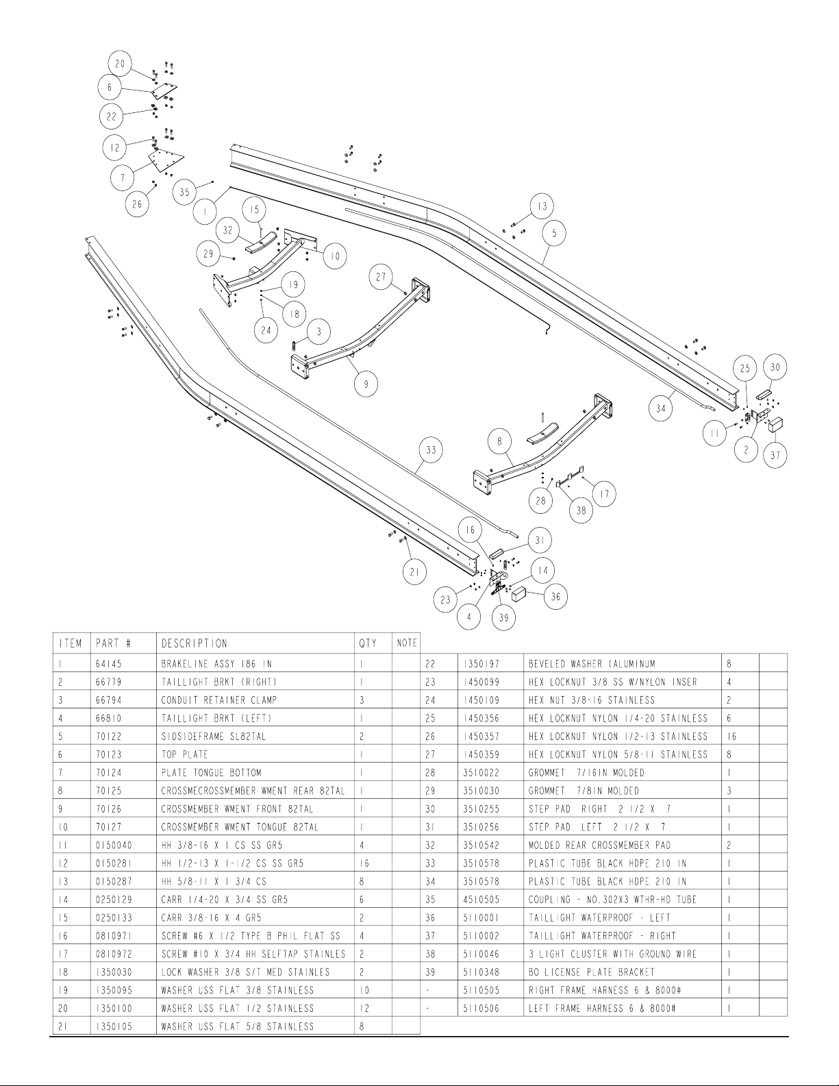
Tongue:
Slide the tongue into the tongue channel weldment on front crossmember. Secure the tongue with a 1/2” X 4 1/2” stainless steel hex
bolt, 1/2” stainless steel at washer and 1/2” stainless steel hex
lock nut with nylon insert.
Secure the tongue to the tongue plate on the frame using two (2)
1/2” X 3 9/16” X 5” square u-bolts and four (4) 1/2” stainless steel
hex lock nut with nylon inserts.
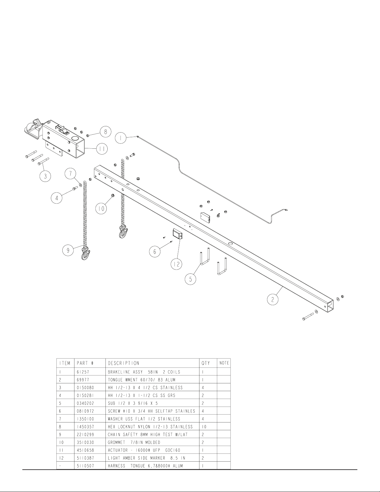
Actuator/ Safety Chain:
Mount the actuator onto the tongue (matching the hole pattern) using three (3) 1/2” X 4 1/2” stainless steel hex bolts and three (3) 1/2”
stainless steel hex lock nuts with nylon inserts. Mount the safety
chains to the front of the tongue using a 1/2” X 1-1/2” stainless
steel hex bolts, followed by a 1/2” stainless steel at washer and
safety chain. Secure this assembly on the inside of the tongue using a 1/2” stainless steel hex lock nut with nylon insert. Repeat the
above instructions on the other side of the tongue.
Straighten the 58" brake line that is included in the brake kit box
and attach to the rear of the actuator. Route brake line thru holes in
the top of the tongue and insert grommets to protect the brake line.
Connect line to the frame line with a tube coupling and tighten.
Midwest Industries, Inc. Ida Grove, IA 51445 800.859.3028 www.shorelandr.com 0004016
Page 4 Rev A 11/18/2008
Page 5
Midwest Industries, Inc. Ida Grove, IA 51445 800.859.3028 www.shorelandr.com 0004016
Page 5 Rev A 11/18/2008
Page 6

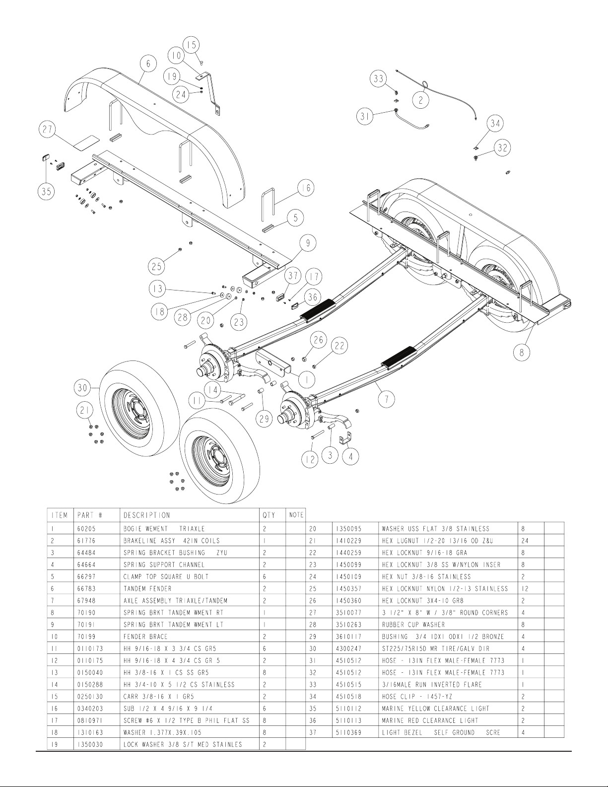
Rocker Bushings:
Install the 3/4” ID X 1” OD X 1-1/2” bronze bushings into the inside
the rocker matching the middle and rear hole patterns. The middle
rocker bushing must be secured with a 3/4” X 5-1/2” stainless steel
hex bolt through the rocker, bushing and the middle shackle on the
spring bracket. Tighten using a 3/4” stainless steel hex lock nut
with nylon insert. The front rocker bushing must be secured with
a 9/16” X 3-3/4” stainless steel hex bolt and 9/16” stainless steel
hex lock nut with nylon insert. Repeat this procedure on the other
rocker on the opposite side of the trailer.
Spring Bracket Bushings:
Install the spring bracket bushing into the spring support channel.
This assembly is then inserted into the rear spring bracket shackle
and secured with a 9/16” X 4-3/4” stainless steel hex bolt and 9/16”
stainless steel hex lock nut with nylon insert. Repeat this procedure
on the other spring bracket on the opposite side of the trailer.
Axle:
First Axle Installation:
Align the eye of the spring on the rst axle with the hole provided in
the spring bracket. From the outside in, insert a 9/16” x 3 ¾” hex
bolt through the spring bracket and the eye of the spring. Secure
with a 9/16” hex lock nut.
Raise the rear hook end of the spring and axle assembly up so it
is up inside the rocker bogie. Secure in place by placing a 9/16” x
3 ¾” hex bolt through the hole in the rocker bogie just below the
spring leaf. Secure with a 9/16” lock nut.
For installtion of the rear axle:
Align the eye of the spring on the third axle with the hole provided
in the rear of the rocker bogie holding the rear of the second axle.
From the outside in, insert a 9/16” x 3 ¾” hex bolt through the
rocker bogie and the eye of the spring. Secure with a 9/16” hex
lock nut.
Raise the rear hook end of the springs on the third axle up into the
spring bracket. Place a spring bushing above the hook leaf of the
spring located inside the spring bracket channel. Secure the spring
in the spring bracket by placing a spring support channel under the
spring. Insert a 9/16” x 4-3/4” hex bolt from the outside-in through
the spring support channel, spring bracket and then through the
spring bushing just placed above the hook spring leaf. Secure using a 9/16” lock nut. Repeat on the other spring.
Brake Line Installation
Sort all of the items in hardware box No. 68732. Locate the long
(90’) brake lines and straighten out by uncoiling on a concrete
oor while walking on the line as you uncoil. The line should be
made as straight as possible to assist in mounting to the axle.
Locate ve (5) line clamps and 1/4” self tapping screws provided
in the kit. Hold the line on the backside of the axle and familiarize
yourself on how it needs to be formed to connect to the brass
blocks on the brake calipers. Form the line so that it can be
routed down the back side of the axle and then over to the brass
block on the calipers.
Remove the lower brass plug from the port in the brass block on
the left brake caliper. Note also that the bolt holding the brass
block to the caliper can be loosened so that the brass block can
be rotated to better accommodate the angle that the brake line
approaches the block on the caliper. Thread the brake line
tting into this port to hold the line in position making sure
that the line does not rub or touch the spring. Re-tighten the
bolt in the brass block if it has been loosened to rotate the block.
Route the line along the back side of the axle and secure to
the axle with the ve (5) clamps and self tapping screws.
Note that the axle is pre-drilled for the mounting screws.
Route the brake line over to the brass block on the right brake
caliper. Remove both plugs on the right caliper block. Thread the
other end of the brake line into the bottom port on the brass block.
Thread the 13” brake hose male end into the other port. Tighten.
Position the brass block so that neither the hose nor the brake line
will contact or rub the spring.
Tighten all ttings.
Place the other end of the hose up through the hole provided in
the brake line clip bracket. Secure in place with the hose clip provided.
Repeat this process on the second axle.
Connecting the Axles Together
Locate the two brass tees. Thread the male port of the tees into the
female end of the 13” brake hoses running up from the axles just
installed on the front and second axles. Tighten.
Remove the plastic cap from the end of the frame brake line coming out of the side frame by the axle. Carefully uncoil the brake line
enough so that it will reach the port of the tee just threaded into the
brake hose. Thread the brake line tting into the top port of the tee
installed on the front axle and tighten.
NOTE: The hook end of the springs must be installed in the same
direction, to the rear of the of the trailer - on both axles!
Brakes:
Refer to the brake manual for service and maintenance.
Tire/Rim Assemblies:
Mount the tire and wheel assemblies using the 1/2” ne threaded
tapered lug nuts provided. Tighten to 85-130 ft./lb. torque using the
rotation pattern as shown in the ShoreLandr’s Owners Manual.
Re-torque the lug nuts after 50 miles driving and then periodically
thereafter.
Midwest Industries, Inc. Ida Grove, IA 51445 800.859.3028 www.shorelandr.com 0004016
Page 6 Rev A 11/18/2008
Page 7

Midwest Industries, Inc. Ida Grove, IA 51445 800.859.3028 www.shorelandr.com 0004016
Page 7 Rev A 11/18/2008
Page 8

Midwest Industries, Inc. Ida Grove, IA 51445 800.859.3028 www.shorelandr.com 0004016
Page 8 Rev A 11/18/2008
Page 9

Refer to your ShoreLand’r Owner’s
Guide and other decals on trailer for
additional information.
SAFETY INSTRUCTIONS
4810709
Proper tongue weight must be maintained.
Rev C 8/28/06
Before towing, check the following to ensure
that:
1. All parts, bolts, nuts and wheel lug nuts
are tight.
2. Tie downs, winch strap and bow-eye
safety chain are secure.
3. Tires are inflated to manufacturer’s
standards. (See tire sidewall)
4. Wheel bearings have adequate grease.
5. Trailer coupler and coupler ball are the
same size.
6. Coupler is properly attached and
secured to coupler ball.
7. Trailer safety chains are crossed under
the tongue and attached to towing
vehicle.
8. All lights are operational. Note: It is
recommended that the trailer lights be
disconnected before backing into the
water.
9. Trailer tongue jack is in up or travel
position.
10. Hitch ball has a rating that is equal to or
greater than the coupler or actuator
GVWR.
11. All wheel lug nuts must be tightened to a
minimum torque rating of 85 ft/lb.
12. Lug nuts must be re-torqued after the
first 50 miles, then periodically thereafter.
4810709 REV 8-06.ai 8/28/2006 7:29:33 AM
Winch Assembly:
Refer to page 8 for winch parts diagram.
The winch post assembly comes factory assembled and ready to
mount on the tongue. Position the winch assembly on the tongue in
a location that would best t your watercraft. Using two (2) 1/2” X 3
9/16” X 5” stainless steel square u-bolts, secure the winch assembly to the tongue. Tighten with four (4) 1/2” stainless steel lock nuts
so that the winch assembly will not slide on tongue. Set the other
mounting plate in position and secure it using two (2) 1/2” X 3 9/16”
X 5” stainless steel square u-bolts and four (4) 1/2” stainless steel
lock nuts. Refer to winch adjustments on page 16.
Midwest Industries, Inc. Ida Grove, IA 51445 800.859.3028 www.shorelandr.com 0004016
Page 9 Rev A 11/18/2008
Page 10

Midwest Industries, Inc. Ida Grove, IA 51445 800.859.3028 www.shorelandr.com 0004016
Page 10 Rev A 11/18/2008
Page 11

Front Bunk or Roller Arm:
Mount the bunk bracket weldment or roller arm tube into the pivot
base weldment using a 1/2” X 4-1/2” stainless steel hex head bolt
and secure with a 1/2” stainless steel hex lock nut with nylon insert.
Mount the bunk assembly onto the bunk bracket weldment using
two (2) 1/2” X 1-1/2” stainless steel hex bolts and secure with two
(2) 1/2” stainless steel hex lock nuts with nylon insert. Repeat this
procedure on the opposite side of the trailer.
Rear Bunk or Roller Arm:
Mount the bunk bracket weldment or roller arm tube into the pivot
base weldment using a 1/2” X 4-1/2” stainless steel hex head bolt
and secure with a 1/2” stainless steel hex lock nut with nylon insert.
Mount the bunk assembly onto the bunk bracket weldment using
two (2) 1/2” X 1-1/2” stainless steel hex bolts and secure with a two
(2) 1/2” stainless steel hex lock nuts with nylon inserts. Repeat this
procedure on the opposite side of the trailer.
Midwest Industries, Inc. Ida Grove, IA 51445 800.859.3028 www.shorelandr.com 0004016
Page 11 Rev A 11/18/2008
Page 12

Midwest Industries, Inc. Ida Grove, IA 51445 800.859.3028 www.shorelandr.com 0004016
Page 12 Rev A 11/18/2008
Page 13

Midwest Industries, Inc. Ida Grove, IA 51445 800.859.3028 www.shorelandr.com 0004016
Page 13 Rev A 11/18/2008
Page 14

Midwest Industries, Inc. Ida Grove, IA 51445 800.859.3028 www.shorelandr.com 0004016
Page 14 Rev A 11/18/2008
Page 15

Midwest Industries, Inc. Ida Grove, IA 51445 800.859.3028 www.shorelandr.com 0004016
Page 15 Rev A 11/18/2008
Page 16

Final Assembly Instructions
Remove the small parts from the frame by cutting the bands. Remove the bolt bag and sort all nuts and bolts by size.
Refer to the individual pages for assembly instruction by bundles.
Reference: Standing at the rear of the trailer will determine the
right and left side of the trailer in the assembly instructions.
The SLB-R-RB-XR82TAL side frames and crossmembers are assembled at the manufacturer. The spring brackets and fenders are
also assembled at the manufacturer.
Cautions and Warnings:
The law requires that the white ground wire on both the tongue wire
harness and vehicle harness be properly grounded to the respective trailer and vehicle frames.
Once the above adjustment is accomplished, hook the bow eye
safety chain into the boat bow eye as extra security to keep the
boat from sliding off the back of the trailer in the event that the
winch fails.
Rear Support System:
Place the boat on the trailer so that the transom is located at the
rear of the support system. On an bunk trailer, the transom of the
boat should be within 1-2” of the end of the bunk. This gives you
maximum support on the transom.
The rear cross member is adjustable forward or backward to allow
the trailer to be adjusted to various length boats. This is accomplished by removing the two bolts that attach the ends of the rear
cross member to each side frame. Slide the assembly to another
set of holes provided in the side frames that is more desirable, and
then re-attach the cross member in the new location with the bolts
just removed.
Check all nuts and bolts; tighten before towing.
Tongue Weight Adjustment:
Tongue weight should be 5% to 7% of the total gross weight of the
boat and trailer combined.
Tongue weight too high, move the axle assembly forward.
Tongue weight too low, move the axle assembly backward.
NOTE: Brake line and wire harness will need care when moving
the assembly.
Adjustments
Winch Post:
Place the boat on the trailer and position it for proper support. Once
the boat is positioned adjust the winch post as follows:
Loosen the U-bolts attaching the winch post mounting bases to the
tongue. Rotate the winch post assembly either upward or downward until the strap coming off the winch is at the same height as
the boat bow eye. Slide the assembly backward until the bow eye
roller about contacts the boat. Place the retainer strap up over the
top of the boat bow eye. Note that the bow roller assembly may
have to be adjusted either up or down on the winch post pivot tube
so that the retainer strap is directly above the boat bow eye as the
bow roller contacts the boat. This is a good starting point for the ne
adjustment of he winch post as described below.
Winch Strap Adjusting Instructions:
Route the winch strap through the loop in the end of the winch post
retainer strap, then attach into the boat bow eye. Winch the boat on
the trailer until the boat is just touching the bow roller of the winch
post assembly. Loosen the bow roller assembly and either raise or
lower until the loop in the winch post retainer strap is positioned on
the top of the boat bow eye. Re-tighten in new position. Winch the
boat securely on the trailer.
Proper adjustment is when the bow roller is in contact with the boat
and the winch post retainer strap is securely pulled onto the top of
the boat bow eye at the same time.
The wire harness for the three-light identication light must be re-
positioned where it comes from the black wire harness tubing to
eliminate slack and sagging of the wiring.
Bunks:
Make sure the bunks are positioned far enough apart to give your
boat as much stability as possible while transporting. Position the
bunks so they are located just to the outside of a strake that your
boat may have. This will help center your boat and assist when
loading. The bunks need to be adjusted up high enough to keep
the keel from resting on the center pads. A minimum of one to two
inches of clearance is desirable.
Front Support System
Bunk
The front bunks should be adjusted either in or out so that the bunk
will run just to the outside of the strake of the boat. The bunks can
be adjusted either farther in or out from the location of the rear
bunk position. Adjust the bunks up so that there is approximately
1” clearance between the keel of the boat and the center cross
member pad.
Read your ShoreLand’r Owner ’s Guide and all safety decals on
the trailer.
Wash and wax your trailer regularly. Always rinse your trailer after
each use, especially when boating in salt or brackish water.
Re-check all fasteners for tightness before towing.
Check the tire pressure before towing.
Contact your authorized ShoreLand’r dealer if you experience a
problem with your trailer.
For further information or assistance, contact ShoreLand’r at
1-800-859-3028 or visit www.shorelandr.com.
Note that they must both make contact at the same time to create
the maximum retaining force of the boat propelling forward in the
event of a panic or sudden stop.
Midwest Industries, Inc. Ida Grove, IA 51445 800.859.3028 www.shorelandr.com 0004016
Page 16 Rev A 11/18/2008
 Loading...