

Page 1
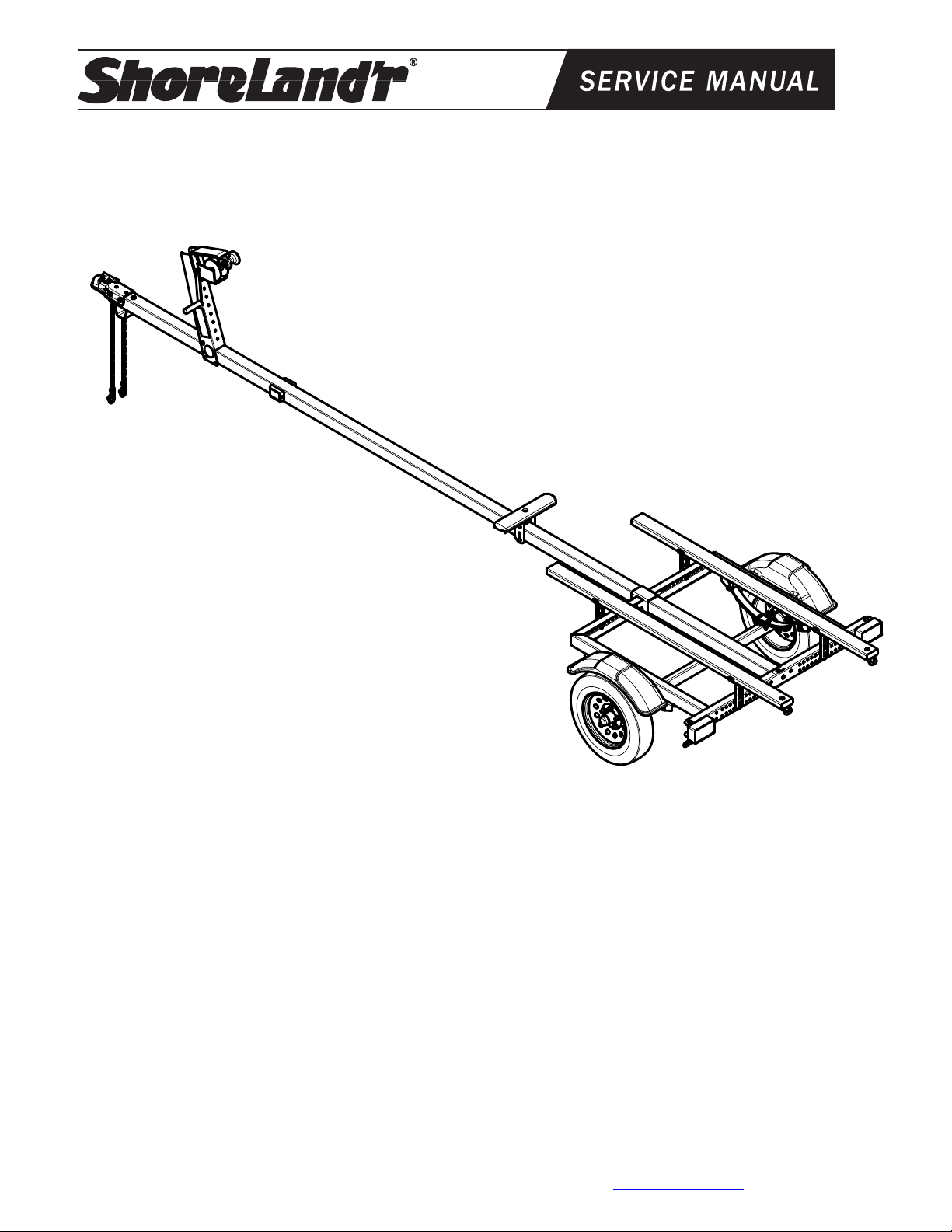
SLB7TS & SLB7TL
SLB7TS-_ _ 700 lb. Tadpull Trailer
* 4.80 X 12-B Tire/T-Silver Mod Rim
or
* 4.80 X 12-B Tire/Galv. Mod Rim
62340 Literature Bag - Trailers
64427-- Tongue, 166F 3 X 3 X 15’
67280-- Frame Bundle - Tadpull
4810501 Decal, ShoreLand’r Chrome
SLB7TL-_ _ 700 lb. Tadpull Trailer
* 4.80 X 12-B Tire/T-Silver Mod Rim
or
* 4.80 X 12-B Tire/Galv. Mod Rim
62340 Literature Bag - Trailers
64428-- Tongue, 166F 3 X 3 X 17’
67280-- Frame Bundle - Tadpull
4810501 Decal, ShoreLand’r Chrome
Midwest Industries, Inc. Ida Grove, IA 51445 800-859-3028 www.shorelandr.com 0002793
Page 1 of 8 Rev A 4/14/2011
ShoreLand’r offers their product line a painted
finish. When ordering parts it is important that you
specify the finish or color you have on your product.
The five (5) digit number along with a two (2) digit
space _ _, note the parts which can be purchased
with various finishes. When ordering these items
use the five (5) digit number along with a two (2)
digit suffix for the proper finish.
00 .........Galvanized
03 .........Black
Page 2
Midwest Industries, Inc. Ida Grove, IA 51445 800-859-3028 www.shorelandr.com 0002793
Page 2 of 8 Rev A 4/14/2011
Page 3

Midwest Industries, Inc. Ida Grove, IA 51445 800-859-3028 www.shorelandr.com 0002793
Page 3 of 8 Rev A 4/14/2011
Page 4

Tongue Weight Adjustment
Approximate Tongue Weights for Best Towing.
Tongue weight too high, move the axle assembly
forward. If the tongue weight is too low, move the axle
assembly backward. The tongue weight should be 5%
to 7% of the total gross weight of the trailer and boat
combined.
Tire Size & Carrying Capacity Chart
Tire Size 4.80X12
Load Range B
Carrying Capacity 780 lbs. per/tire
Refer to tire side wall for correct tire pressure.
Midwest Industries, Inc. Ida Grove, IA 51445 800-859-3028 www.shorelandr.com 0002793
Page 4 of 8 Rev A 4/14/2011
Page 5

Midwest Industries, Inc. Ida Grove, IA 51445 800-859-3028 www.shorelandr.com 0002793
Page 5 of 8 Rev A 4/14/2011
Page 6

Midwest Industries, Inc. Ida Grove, IA 51445 800-859-3028 www.shorelandr.com 0002793
Page 6 of 8 Rev A 4/14/2011
Page 7

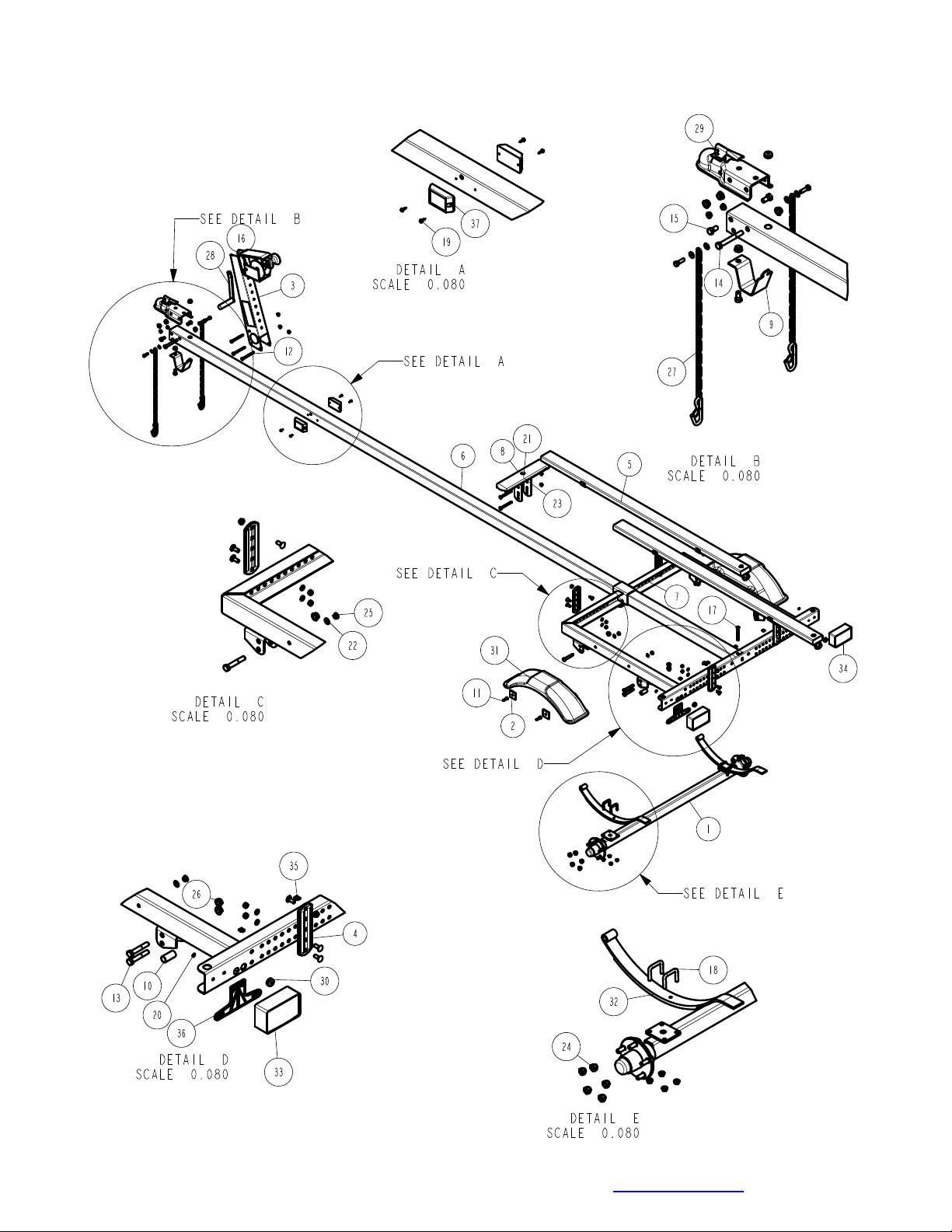
The assembly is attached to the tongue with two 3/8” X 4”
carriage bolts, one on each the top and bottom side of the
tongue. They are secured in place with 3/8” flange lock
nuts provided.
Note that the assembly is adjustable both up and down. It
is able to be slid forward and backward on the tongue.
Adjust to its proper position. Secure in place by tightening
the bolts just installed. Assembly is complete.
Midwest Industries, Inc. Ida Grove, IA 51445 800-859-3028 www.shorelandr.com 0002793
Page 7 of 8 Rev A 4/14/2011
Page 8

Final Assembly Instructions
g
Remove the small parts from the frame by cutting the
bands. Remove the bolt bag and sort all bolts and nuts
by size.
Tongue:
Install the tongue through the center of the frame.
Unwind the tongue harness. Thread the harness
through the 13/16” diameter hole on the coupler end of
the tongue. Pull the harness out of the tongue through
the 13/16” diameter hole on the left side at the rear of
the tongue. Insert the rubber grommets in the 13/16”
diameter hole on the left side at the rear of the tongue
and around the wire harness in the front of the tongue.
Fasten the rear of the tongue to the back of the frame
using a 3/8” X 4” carriage bolt and 3/8” flange lock nut.
At the front of the frame and the tongue, then put on
the 3/8” flat washer and 3/8” flange lock nut. Tighten
both bolts, but do not over tighten.
Plug in the tongue harness to the frame wiring. Wiring
is complete.
Safety Chain:
Insert a 3/8” X 1-1/4” hex bolt with a 3/8” flat washer
and safety chain through the lower hole on the front of
the tongue. Secure with a 3/8” flange lock nut. Repeat
this procedure on the opposite side of the tongue.
Coupler:
Mount the coupler onto the tongue with one (1) 1/2” X
4” hex bolt and two (2) 1/2” X 1” hex bolts. Secure with
1/2” flange lock nuts. Refer to the parts drawing for
placement.
Winch:
The winch post assembly is pre-assembled and is
shipped banded to the frame. Place the winch post on
the tongue in the approximate location. Attach to the
tongue using three (3) 3/8” X 4” hex bolts and 3/8”
flange lock nuts. It can be left loose until the boat is
placed on the trailer for final adjustment.
Place the winch handle on the drive shaft of the winch
by mating the flat sides of the drive shaft with the
punched hole in the winch handle. Secure the handle
to the drive shaft with the 1/2” lock nuts provided.
Tighten.
Springs:
Fasten the springs to the axle with the 3/8” axle u-bolts
and secure with 3/8” flange lock nuts.
Axle:
Position the axle with springs under the frame. Place
the spring bushing spacer into the rear frame brackets.
Align with the top hole and secure into the bracket with
a 1/2” X 3” hex bolt and 1/2” flan
e lock nut. Tighten.
If your trailer is equipped with 8” tires, place the slipper
end of the spring above the bushing installed and
secure the front eye of the spring in the top hole in the
bracket with a 1/2” X 3” hex bolt and 1/2” flange lock
nut.
When installing 12” tires on this unit, install a 1/2” X 3”
hex bolt into the bottom hole in the rear bracket.
Tighten, but do not over tighten. Insert the slipper end
of the spring between the two (2) bolts installed into the
back bracket. Secure the eye of the spring into the
bottom hole of the front bracket with a 1/2” X 3” hex
bolt and 1/2” flange lock nut. Tighten. Tighten all bolts
and nuts, but do not over tighten.
Remove the 1/2” lug nuts from the hardware bag.
Mount the tire and rim assemblies with 1/2” lug nuts
using 80-90 ft. lbs. of torque using a proper tightening
procedure.
Bunk:
Position tow (2) long 2X4 bunks on the frame. Fasten
in a desired location that best fits your watercraft using
3/8” carriage bolts, 3/8” lock washer and 3/8” hex nuts.
Refer to parts drawing for placement.
Assembly should be complete except for tightening
some of the bolts. These bolts were left loose to aid in
adjusting the trailer to the boat only. All bolts and nuts
must be tightened before towing
NOTE: The law requires that the white ground wire on
both the tongue wire harness and vehicle harness be
properly grounded to the respective trailer and vehicle
frames.
ADJUSTMENT INSTRUCTIONS:
Bunk Adjustments:
Place your bolt on the trailer.
Determine the spacing on the bunks. It may be
necessary to adjust your bunks either further in or out
from the position you have it assembled. They must be
adjusted to miss any keel or strake which might be on
your particular watercraft.
IMPORTANT:
The bunks should be spaced as far apart as possible
for stability. This in most cases will also allow your
water craft to be as low as possible on the trailer for
better trailering, loading and unloading.
NOTE: The rear tie-down straps are not provided with
the trailer.
NOTE: Check all fasteners and tighten before towing.
Midwest Industries, Inc. Ida Grove, IA 51445 800-859-3028 www.shorelandr.com 0002793
Page 8 of 8 Rev A 4/14/2011
 Loading...