

Page 1
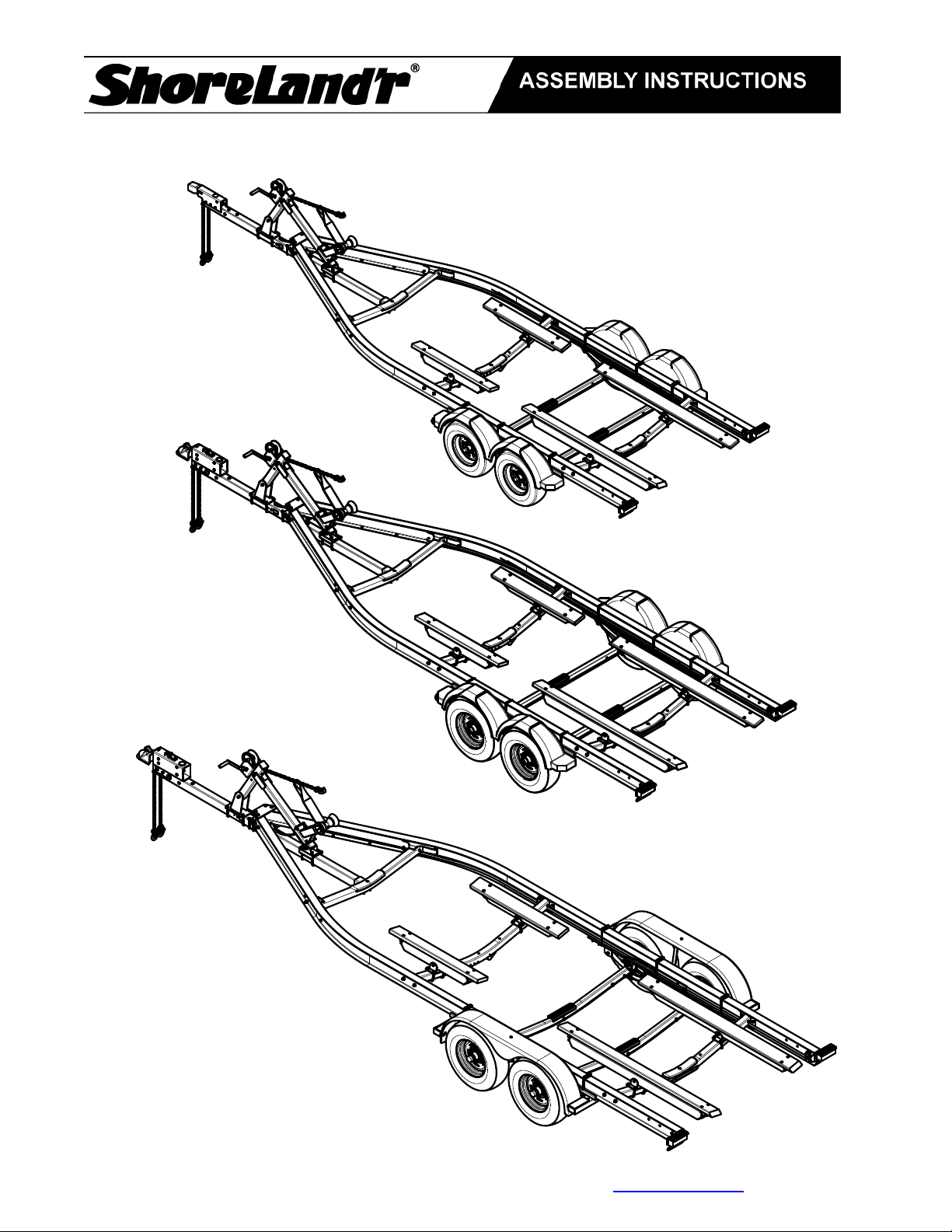
SLB60TAL, SLB70TAL, & SLB82TAL
ASSEMBLY INSTRUCTIONS
Midwest Industries, Inc. Ida Grove, IA 51445 800-859-3028 www.shorelandr.com 0004303
Page 1 of 13 2/15/2011
Page 2

Special caution should be taken that while assembling these stainless steel
components to use Anti-seize compound on the threads to help prevent gauling.
Final Assembly Instructions
Remove the small parts from the frame by cutting the bands. Remove the bolt bag and sort all
nuts and bolts by size.
Refer to the following pages for assembly instruction by components.
Reference: Standing at the rear of the trailer will determine the right and left side of the trailer
in the assembly instructions.
The trailer side frames and crossmembers are assembled at the manufacturer. The spring
brackets and fenders are also assembled at the manufacturer.
Tools for Assembly
Wrenches: 9/16, 3/4, 7/8, & 1 1/8
Sockets: 9/16, 3/4, 13/16. & 1 1/8
Tools for connecting brakes:
Wrenches: 7/16, 3/8, 5/8, & 12mm and also a 3/8 nut driver
Safety Instructions
• Always wear personal protective equipment (safety glasses, gloves, etc) when
assembling and installing components.
• Inspect all fasteners regularly for deterioration and fastener tension. Refer to the
exploded part views for fastener locations in the appropriate parts manual.
• Replace any and all components that show deterioration due to wear or misuse before
using your boat trailer.
• Never modify parts and components. Always replace components with genuine
Shoreland’r replacement parts.
Midwest Industries, Inc. Ida Grove, IA 51445 800-859-3028 www.shorelandr.com 0004303
Page 2 of 13 2/15/2011
Page 3
Assembly Instructions
r
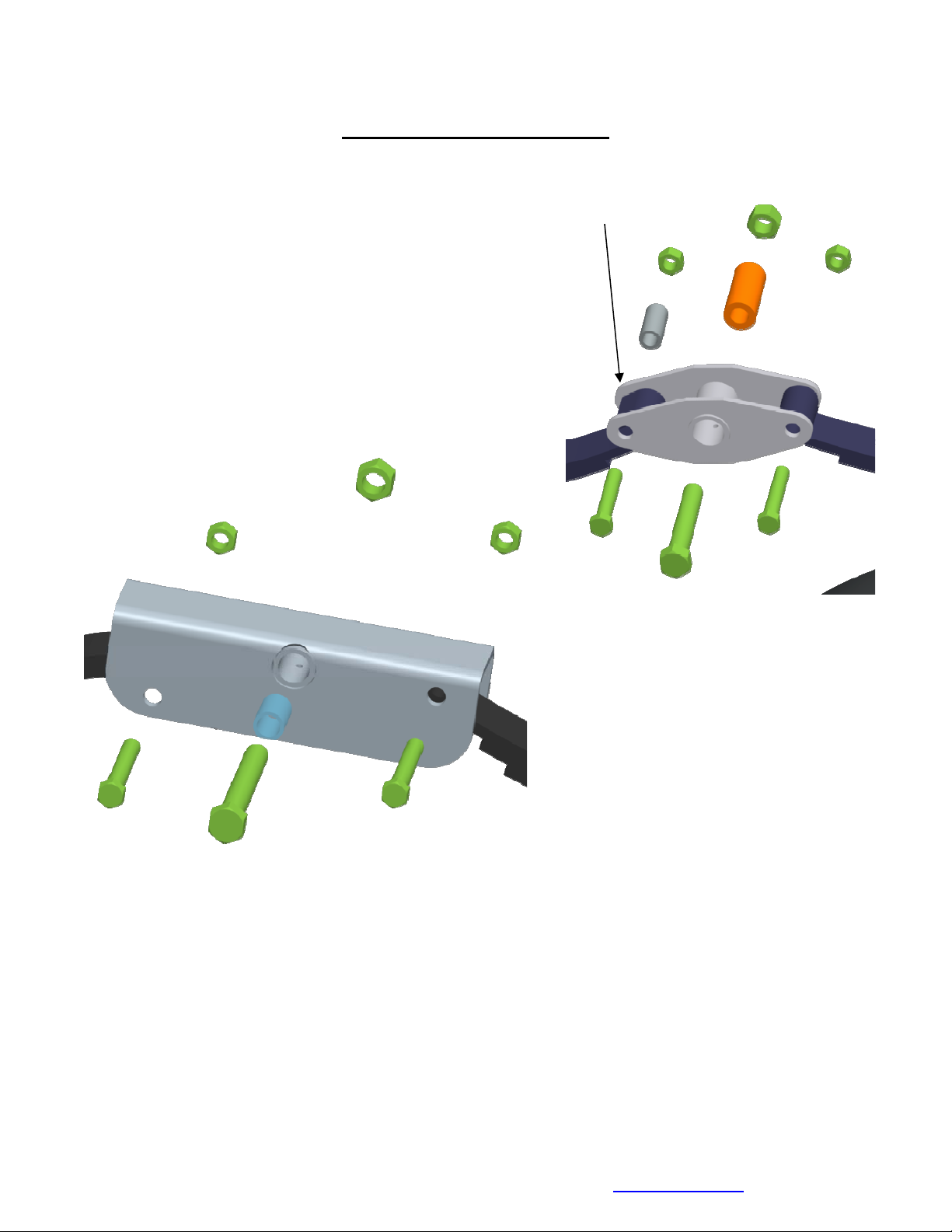
Rocker Bushings and/or Bogie:
Note there is a grease zerk in the center bushing of
the rocker bogie. Position the rocker bogie into the
center mounting channel of the spring bracket so
that the grease zerk is pointing down. This is
necessary so that it can be serviced in the field
when needed. Align the center hole of the rocker with
the center hole of the spring bracket. Insert and secure
with a 3/4” X 4-1/2” stainless steel hex bolt from the
outside in and tighten with a 3/4” stainless steel hex lock
nut. Install the 3/4” ID X 1” OD X 1-1/2” bronze bushings
into the inside the rocker matching the middle and rear
Rocker/Boogie 8200#
Trailer
To Front of
Traile
hole patterns. The middle rocker
bushing must be secured with a 3/4” X
5-1/2” stainless steel hex bolt through
the rocker, bushing and the middle
shackle on the spring bracket. Tighten
using a 3/4” stainless steel hex lock nut
with nylon insert. The front rocker
bushing must be secured with a 9/16”
X 3-3/4” stainless steel hex bolt and
9/16” stainless steel hex lock nut with
nylon insert. Repeat this procedure o
the other rocker on the opposite side of
the trailn er.
Spring Bracket Bushings:
Place one of the spring bracket bushings into the rear of the spring bracket and secure with a
9/16” x 3 1/4” stainless steel hex bolt and 9/16” stainless steel hex lock nut. Repeat in other
spring bracket. Install another spring bracket bushing in the front hole on the rock arm
Midwest Industries, Inc. Ida Grove, IA 51445 800-859-3028 www.shorelandr.com 0004303
Page 3 of 13 2/15/2011
Page 4
assembly. Secure with a 9/16” x 3-1/4” hex bolt and lock
nut. Install the spring bracket bushing into the spring
support channel. This assembly is then inserted into the
rear spring bracket shackle and secured with a 9/16” X
4-3/4” stainless steel hex bolt and 9/16” stainless steel
hex lock nut with nylon insert. Repeat this procedure on
the other spring bracket on the opposite side of the
trailer.
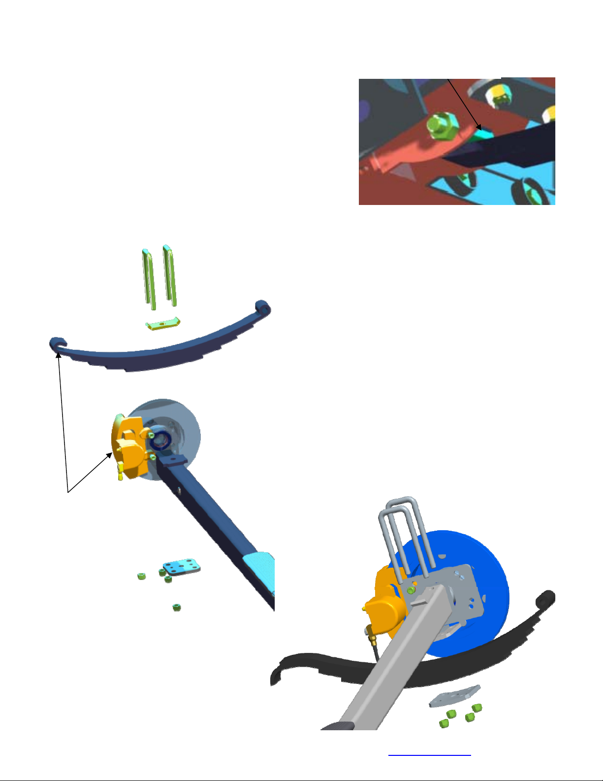
Axle:
Note: The hook end of the springs must be toward the rear of the trailer, on both axles!
Spring Bracket Bushing
Position the axles so they are properly aligned
with the trailer. Position the brake axle so that the
disc brake calipers are on the back side of the
axle. Place the springs on the topside of the spring
pads welded to the axle. Place a spring clamp on
the top center of the spring. Place the 1/2” x 6-1/2”
stainless steel square U-bolts down over the top of
the spring clamp, spring and axle.
Place the spring and axle U-bolt plate onto the
ends of the two U-bolts. Secure in place with 1/2”
stainless steel lock nuts. Thread onto the U-bolts
but do not tighten securely until the complete unit
is in position on the trailer. Repeat on the other
spring.
Hook on
leaf spring
& Brake
Caliper to
the rear of
Trailer
Midwest Industries, Inc. Ida Grove, IA 51445 800-859-3028 www.shorelandr.com 0004303
Page 4 of 13 2/15/2011
Page 5
NOTE: The hook end of the springs must be
p
of the trailer - on both axles!
First Axle Installation:
For rear axle 6000 & 70
Position the rear axle under the frame
loop of the spring around the bushings just installed.
Note that if the axle is positioned too low when trying to
hook, the hooks will not hook around the bushings.
Raise the front of the springs up so they align with
rear hole in the axle rocker bogie just installed. Secure
in place with 9/16” x 3-1/4” stainless steel hex bolts and
9/16” stainless steel lock nuts.
00lb trailers:
, hook the hook
installed in the same direction, to the rear
the
F
or front axle 8200lb trailers:
Align the eye of the spring on the
the outside in, insert a 9/16” x 3 3/4” hex bolt through the spring bracket and the eye of the
spring. Secure with a 9/16” hex lock nut.
first axle with the hole provided in the spring bracket. From
Raise the rear hook end of the spring and
axle assembly up so it is up inside the rocker
bogie. Secure in place by placing a 9/16” x
3/4
” hex bolt through the hole in the rocker
bogie just below the spring leaf. Secure with a
9/16” lock nut.
3
Hook end of leaf
ring
s
Second A
For front axle 6000 & 7200lb
trailers:
Hook the hook end of the springs
mounted to the front axle over the
bushing just installed in the rocker
arm assembly. Then swing the front
of the spring up and attach the front
mounting hole
ith another 9/16” x 3-1/4” hex bolt
w
nd lock nut.
a
xle Installation:
in the spring bracket
Midwest Industries, Inc. Ida Grove, IA 51445 800-859-3028 www.shorelandr.com 0004303
Page 5 of 13 2/15/2011
Page 6
For rear axle 8200lb trailers:
Align the eye of the spring on the second
bogie holding the rear of the first axle.
through the rocker bogie and the eye of the
Raise the rear hook end of the springs on the th
axle with the hole provided in the rear of the rocker
om the outside in, insert a 9/16” x 3 3/4” hex bolt
Fr
spring. Secure with a 9/16” hex lock nut.
spring bushing above the hook leaf of the spring
located inside the spring bracket channel. Secure the
spring in the spring bracket by placing a spring
support channel under the spring. Insert a 9/16” x 43/4” hex bolt from the outside-in through the spring
support channel, spring bracket and then through the
spring bushing just placed above the hook spring
leaf. Secure u
other spring.
Tighten all axle U-bolts and spring bolts.
ird axle up into the spring bracket. Place a
sing a 9/16” lock nut. Repeat on the
Spring Support
Channel
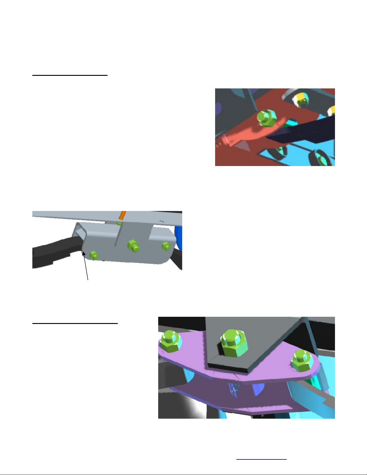
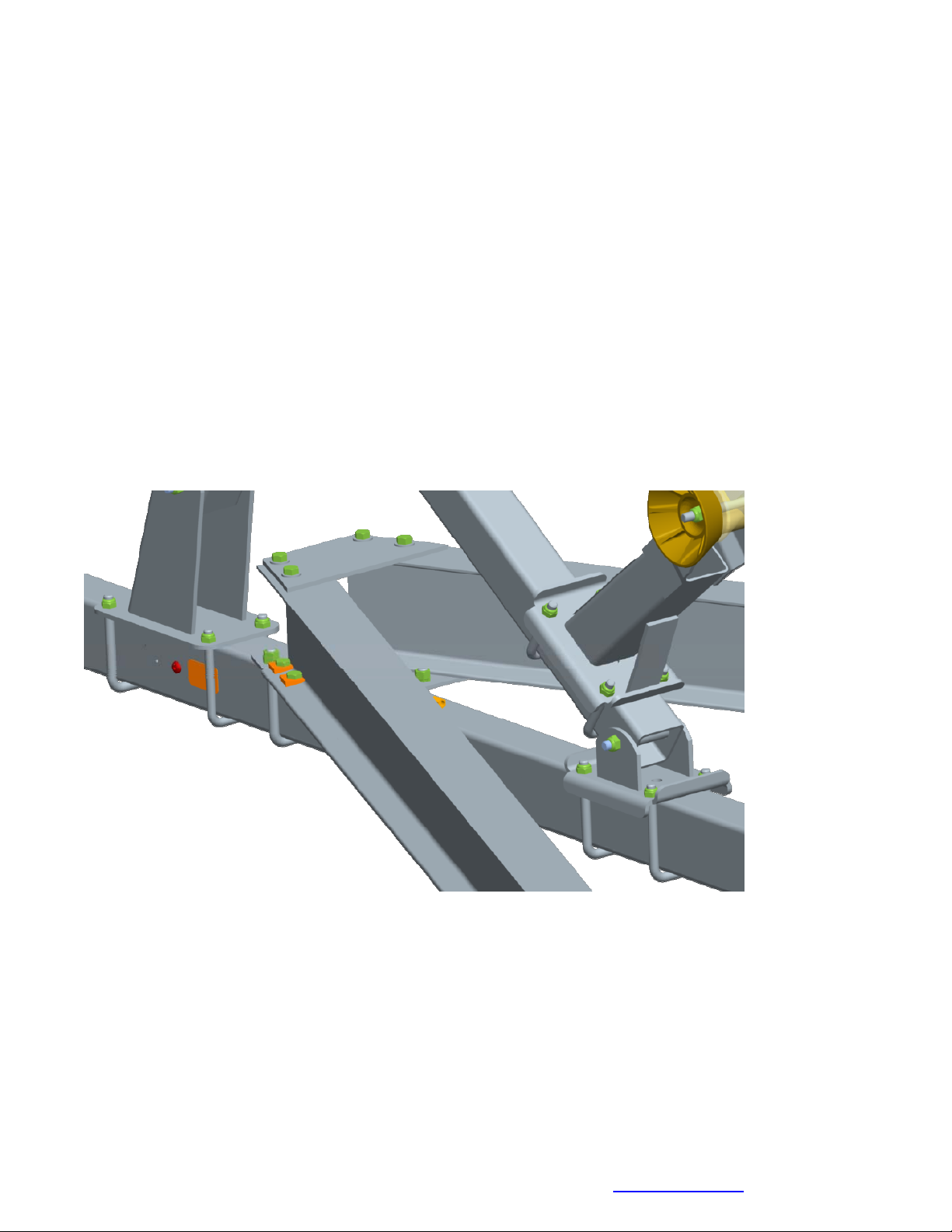
ongue Assembly:
T
lide the tongue into the tongue
S
annel weldment on front
ch
ossmember. Secure the tongue with
cr
1/2” X 4 1/2” stainless steel hex bolt,
a
/2” stainless steel flat washer and 1/2”
1
ainless steel hex lock nut with nylon
st
sert.
in
Midwest Industries, Inc. Ida Grove, IA 51445 800-859-3028 www.shorelandr.com 0004303
Page 6 of 13 2/15/2011
Page 7
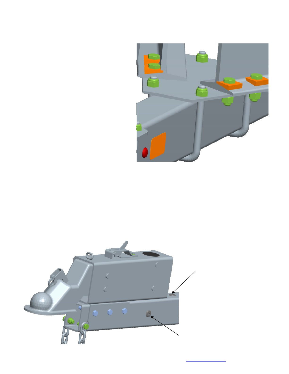
Secure the tongue to the tongue plate on
e frame using two (2)1/2” X 3 9/16” X 5”
th
quare u bolts and four (4) 1/2” stainless
s
teel hex lock nut with nylon inserts.
s
ctuator/ Safety Chain:
A
ount the actuator onto the tongue (matching the hole pattern)
M using three (3) 1/2” X 4 1/2”
ainless steel hex bolts and three (3) 1/2” stainless steel hex lock nuts with nylon inserts.
st
ount the safety chains to the front of the tongue using a 1/2” X 1-1/2” stainless steel hex
M
olts, followed by a 1/2” stainless steel flat washer and safety chain. Secure the components
b
on the inside of the tongue
the above instructions on the other side of the tongue.
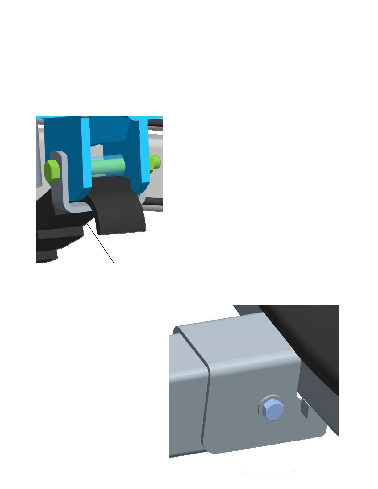
Remove the 58" brake hose that is included in the brake kit box and attach to the rear of th
actuator. Route brake hose thru holes in the top of the tongue and insert grommets to prote
using a 1/2” stainless steel hex lock nut with nylon insert. Repeat
the brake line hose. Connect
line to the frame hose with a
tube coupling and tighten.
Insert hose here
e
ct
Tongue Harness Vehicle
onnections comes thru herec
Midwest Industries, Inc. Ida Grove, IA 51445 800-859-3028 www.shorelandr.com 0004303
Page 7 of 13 2/15/2011
Page 8

BSrake Line Installation
ort all of the items in brake kit box.
ocate the long (90’) brake lines
L
nd straighten out by uncoiling.
a
Locate five (5) line clamps
elf tapping screws provided is
it.
k
Remove the lower plastic
and 1/4”
n the
plug from
the port in the brass block on the
left brake caliper. Note also that the
bolt holding the brass block to the
caliper can be loosened so that the
brass block can be rotated to better
accommodate the angle that the
brake hose approaches the block
on the caliper. Thread the brake hos
rub or touch the spring. Re-tighten th
the block. Route the hose along the
(5) clamps and self tapping screws.
Route the brake hose over to the bra
the right caliper block. Thread the ot
e fitting into this port making sure that the line does not
e bolt in the brass block if it has been loosened to rotate
back side of the axle and secure to the axle with the five
Note that the axle is pre-drilled for the mounting screws.
ss block on the right brake caliper. Remove both plugs on
her end of the brake hose into the bottom port on the
brass block. Thread the 18” brake hose male end into the other port. Tighten.
Set the position the brass block so that no components will make contact or rub on the sprin
Tighten all fittings.
Place the other end of the hose up
through the hole provided in the
brake line clip bracket. Secure in
place with the hose clip provided.
Repeat this process on the second
axle.
g.
Connecting the Axles Together
Locate the brass tee. Thread the
male port of the tee into the femal
end of the 18” brake hose running
up from the axle just installed on
the se
R
cond axle. Tighten.
emove the plastic cap from the end of the frame brake hose coming out of the side frame by
the axle. Carefully pull the brake ho
on the second axle and tighten.
Thread the 60” brake hose into the o
clip thru the large hole on the end a
block. Tighten these connections.
things take two (2) clamps and two (2) self-tapping screws and attach to the I-beam.
Midwest Industries, Inc. Ida Grove, IA 51445 800-859-3028 www.shorelandr.com 0004303
Page 8 of 13 2/15/2011
e
se enough so that it will reach the top port of the tee just
ethreaded into the brake hose. Thr
ad the brake hose fitting into the top port of the tee installed
ther port on the tee. Route the hose over to the brake line
nd then down and thread into the side port on the brass
To prevent the hose from sagging and getting caught on
Page 9
Brakes:
Refer to the brake manual for service and maintenance.
Tire/Rim Assemblies:
ount the tire and wheel assemblies using the 1/2” fine threaded tapered lug nuts provided. M
Tighten to
Owners Manual.
R
e-torque the lug nuts after 50 miles driving and then periodically thereafter.
Winch Assembly:
The winch post assembly comes factory assembled and ready to mount on the tongue.
Position the winch assembly on the tongue in a location that would best fit your watercraf
Using two (2) 1/2”
th
e tongue. Tighten with four (4) 1/2” stainless steel lock nuts so that the winch assembly will
85-130 ft./lb. torque using the rotation pattern as shown in the ShoreLandr’s
X 3 9/16” X 5” stainless steel square u-bolts, secure the winch assembly to
t.
not slide on tongue. Set the other mounting plate in position and secu
3 9/16” X 5” stainless steel square u-bolts and four (4) 1/2” stainless steel lock nuts. Refer to
winch adjustments in the trailer adjustments section in the last section.
re it using two (2) 1/2” X
Midwest Industries, Inc. Ida Grove, IA 51445 800-859-3028 www.shorelandr.com 0004303
Page 9 of 13 2/15/2011
Page 10

Front Bunk:
M
ount the bunk bracket weldment
in
to the pivot base weldment using
a
1/2” X 4-1/2” stainless steel hex
h
ead bolt and secure with a 1/2”
st
ainless steel hex lock nut with
nylon insert.
Mount the bunk assembly onto the
bunk bracket weldment using two
(2) 1/2” X 1-1/2” stainless steel
hex bolts and secure with two (2)
1/2” stainless steel hex lock nuts
with nylon insert. Repeat this pro
cedure on the opposite side of the trailer.
Rear Bunk:
Mount the bunk bracket weldment
into the pivot base weldment using a 1/2” X 4-1/2” stainless
steel hex head bolt and secure with a 1/2” stainless steel hex lock nut with nylon insert.
Mount the bunk assembly onto the bunk bracket weldment using two (2) 1/2” X 1-1/2” stainless
steel hex bolts and secure with a two (2) 1/2” stainless steel hex lock nuts with nylon inserts.
Repeat this procedure on the opposite side of the trailer.
Tongue Weight Adjustment:
Tongue weight should be 5% to 7% of the total gross weight of the boat and trailer comb
Tongue weight too high, move the axle assembly forward.
Tongue weight too low, move the axle assembly backward.
NOTE: Brake line and wire harness will need care when moving the assembly.
ined.
Adjustments
Winch Post:
rt. Once the boat is positioned Place the boat on the trailer and position it for proper suppo
adjust the winch post as follows: Loosen the U-bolts attaching the winch post mounting bases
to the tongue. Rotate the winch post assembly either upward or downward until
oming off the winch is at the same height as the boat bow eye. Slide the assembly backward c
until the bow eye ro
the winch post pivot tube so that the retainer strap is directly above the boat bow eye as the
bow roller contacts the boat. This is a good starting point for the fine adjustment of the winch
post as described below.
ller about contacts the boat. Place the retainer strap up over the top of the
that the bow roller assembly may have to be adjusted either up or down on
Noteboat bow eye.
the strap
Midwest Industries, Inc. Ida Grove, IA 51445 800-859-3028 www.shorelandr.com 0004303
Page 10 of 13 2/15/2011
Page 11

Winch Strap Adjusting Instructions:
Route the winch strap through the loop in the end of the
winch post retainer strap, then attach into the boat bow eye.
Winch the boat on the trailer until the boat is just touching the
bow roller of the winch post assembly. Loosen the bow roller
ssembly and either raise or lower until the loop in the winch
a
post retainer strap is positioned on the t
eye. Re-tighten in new position. Winch the boat securely
op of the boat bow
on
the trailer.
Proper adjustment is when the bow roller is in contact with
the boat and the winch post retainer strap is securely pulled
onto the top of the boat bow eye at the same time. Note that
they must both make contact at the same time to create the
maximum retaining force of the boat propelling forward in the
event of a p
anic or sudden stop.
Once the above adjustment is accomplished, hook the bow
eye safety chain into the boat bow eye as extra security to
keep the boat from sliding off the back of the trailer in the
event that the winch fails.
Rear Support System:
Place the boat on the trailer so that the transom is located at
the rear of the support system. On an bunk trailer, the
transom of the boat should be within 1-2” of the end of the
bun
k. This gives you maximum
support on the transom.
he rear cross member is adjustable forward or
T
various length boats. This
is accomplished by
the rear cross member to each side frame. Slide the assembly
in the side frames that is more desirable, and then re-a
backward to allow the trailer to be adjusted to
removing the two bolts that attach the ends of
to another set of holes provided
ttach th
e cross member in the new
location with the bolts just removed.
The wire harness for the
three-light identification light must be repositioned where it comes
from the black wire harness tubing to eliminate slack and sagging of the wiring.
Bunks:
Make sure the bunks are positioned far enough apart to give your boat as much stability as
possible while transporting. Position t
he bunks so they are located just to the outside of a
strake that your boat may have. This will help center your boat and assist when loading. The
bunks need to be adjusted up high enough to keep the keel from resting on the c
inimum of one to two inches of clearance is desirable.
m
enter pads. A
Front Support System
Bunk
The front bunks should be adjusted either in or out so that the bunk will run just to the outside
of the strake of the boat. The bunks can be adjusted either farther in or out from the location of
the rear bunk position. Adjust the bunks up so that there
etween the keel of the boat and the center cross member pad.
b
is approximately 1” clearance
Midwest Industries, Inc. Ida Grove, IA 51445 800-859-3028 www.shorelandr.com 0004303
Page 11 of 13 2/15/2011
Page 12

Read your ShoreLand’r Owner’s Guide and all safety decals on the trailer.
Wash and wax your trailer regularly. Always rinse your trailer after each use, especially when
boating in salt or brackish water.
e-check all fasteners for tightness before towing.
R
heck the tire pressure before towing.
C
Contact your authorized ShoreLa
or further information or assistance, contact ShoreLand’r at 1-800-859-3028 or visit
F
nd’r dealer if you experience a problem with your trailer.
www.shorelandr.com.
Midwest Industries, Inc. Ida Grove, IA 51445 800-859-3028 www.shorelandr.com 0004303
Page 12 of 13 2/15/2011
Page 13

Midwest Industries, Inc. Ida Grove, IA 51445 800-859-3028 www.shorelandr.com 0004303
Page 13 of 13 2/15/2011
 Loading...