

Page 1
®
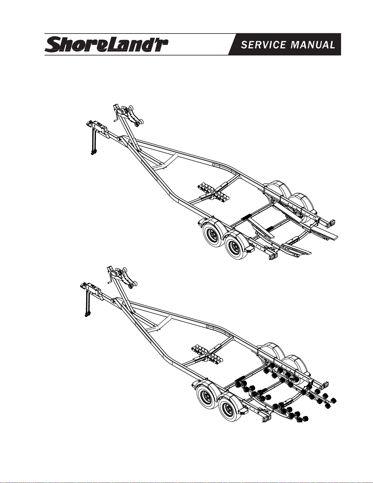
SLB58T & SLR58T
3X5 Trailers
SLB58T
SLB58T 3X5 Bunk Trailer
61778-- 36” Bunk Assembly with Brackets
62340 Literature Bag - Trailers
62466-- Support Tube Assembly for 3X5
4300199 ST215/75R 14C Tire/MSilver Directional Rim
4510354 Actuator - 8000 lb. UFP - Plated
67979-- Tongue Weldment - 81”
68140 Brake Kit Axle 3X5 - 5800
68230-- Frame Bundle 3X5 B&R58T
SLR58T
SLR58T 3X5 Roller Trailer
60617-- 24-1/2” Roller Arm Assembly
62340 Literature Bag - Trailers
62466-- Support Tube Assembly for 3X5
4300199 ST215/75R 14C Tire/MSilver Directional Rim
4510354 Actuator - 8000 lb. UFP - Plated
67979-- Tongue Weldment - 81”
68140 Brake Kit Axle 3X5 - 5800
68230-- Frame Bundle 3X5 B&R58T
Midwest Industries, Inc. Ida Grove, IA 51445 (800)859-3028 www.shorelandr.com M304016
Page 1
Page 2
Midwest Industries, Inc. Ida Grove, IA 51445 (800)859-3028 www.shorelandr.com M304016
Page 2
Page 3
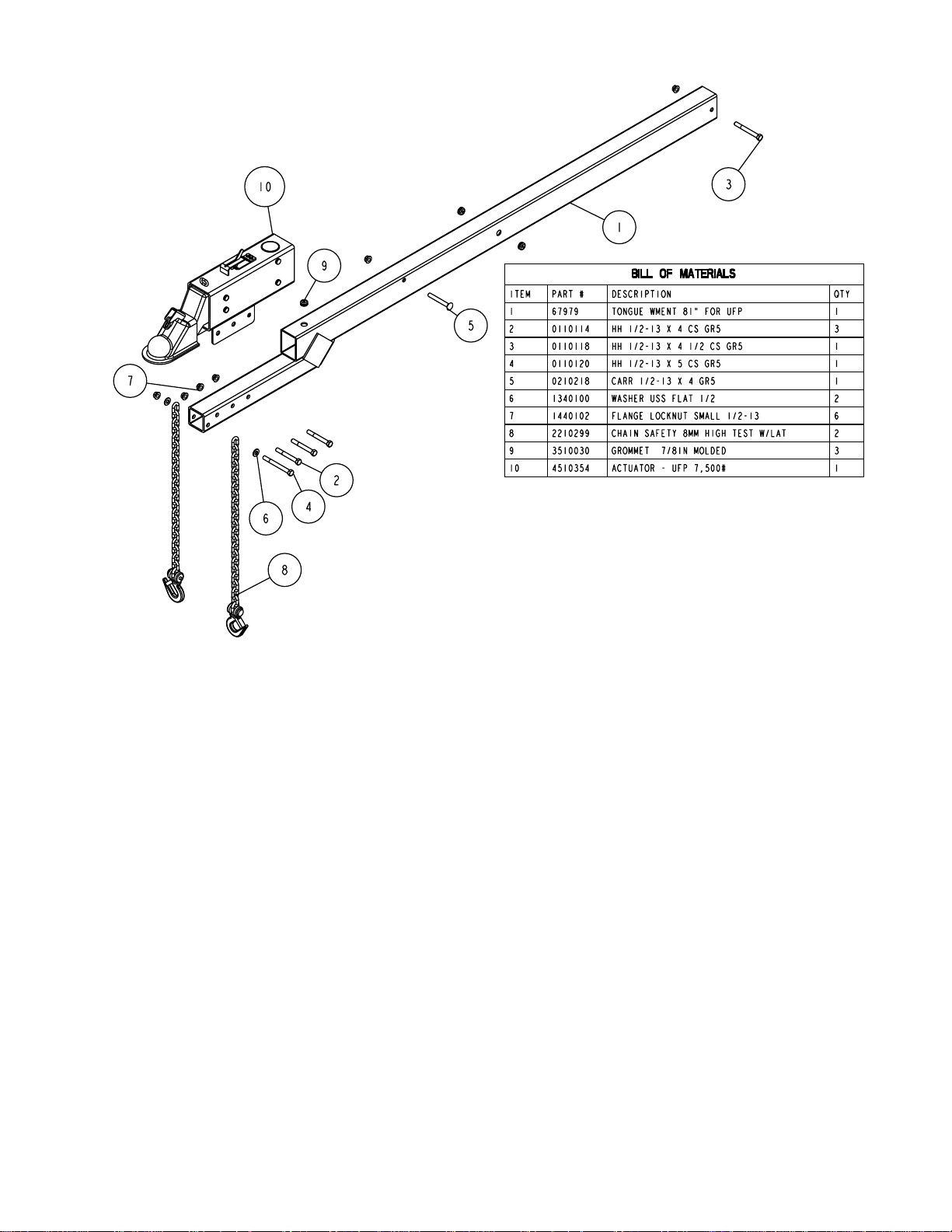
Ton gue
The tongue comes shipped separately. Locate and install
under the frames front tongue channel and in the channel
welded to the front cross member which will support the rear
of the tongue.
Line the hole in the tongue with the hole in the tongue
channel. Install the 1/2” x 4-1/2” carriage bolt in the front cross
hole and secure with a 1/2” lock nut. Secure the rear of the
tongue to the frame with a 1/2” x 4” hex bolt and lock nut.
Tighten.
Brake Line
Remove the brake line from the brake kit box 68140. Locate
the 58” tongue line. Uncoil the line and insert one end into
the rear of the tongue pushing it forward until the end comes
out of the front of the tongue. Locate the brass brake line
coupling in the hardware box and thread on the rear fitting of
the brake line.
Actuator
Locate the actuator, and position it on the front of the tongue
as shown. Look into the back end of the actuator and locate
the solenoid. Note there is a wire harness coiled around the
round solenoid. Uncoil the wire and plug it into the bullet plug
on the end of the blue wire of the tongue harness. Remove
the plastic plug from the port in the rear of the solenoid Thread
the fitting on the end of the tongue brake line into the port the
of the solenoid. Tighten.
Align the holes in the actuator with the holes in the tongue.
Secure the actuator to the tongue using three (3) 1/2” x 4”
hex bolts and lock nuts. Tighten.
Tongue Wire Harness
Locate the tongue wire harness. Place the end of the wire
harness with the two double plugs into the hole in the top of
the tongue. Pull backwards through the tongue until they can
be fished through the holes in each side of the tongue. Note
that the brown and yellow plug must go to the left side of the
trailer and the brown and green plug must go to the right side
of the trailer.
Plug the tongue wire harness ends into the frame harnesses
by matching colors and ends. Place grommets into all the
wire holes. Push the extra wire provided either into the hole
in the tongue or else remove the grommet in the side frame
and place the extra wire in the side frame. Replace grommet
just removed.
Midwest Industries, Inc. Ida Grove, IA 51445 (800)859-3028 www.shorelandr.com M304016
Thread the brass coupling provided on the other end of the
brake line just installed. Bend the line coming out the rear of
the tongue in a smooth gradual radius being careful not to
kink the line. Bend so it can be mated to the brake line from
the side frame. Once aligned thread the side frame brake
line into the other end of the coupling. Tighten both lines into
the coupling.
Safety Chains
Mount the safety chains to the front of the tongue by placing
a 1/2” flat washer onto a 1/2” x 5” hex bolt, then insert the bolt
through the last link on one of the safety chains provided.
Insert the bolt through the hole provided in the front of the
tongue as shown. Once the bolt is completely inserted, place
on the other safety chain provided. Place on another 1/2” flat
washer and secure with a 1/2” hex lock nut. Tighten.
Page 3
Page 4
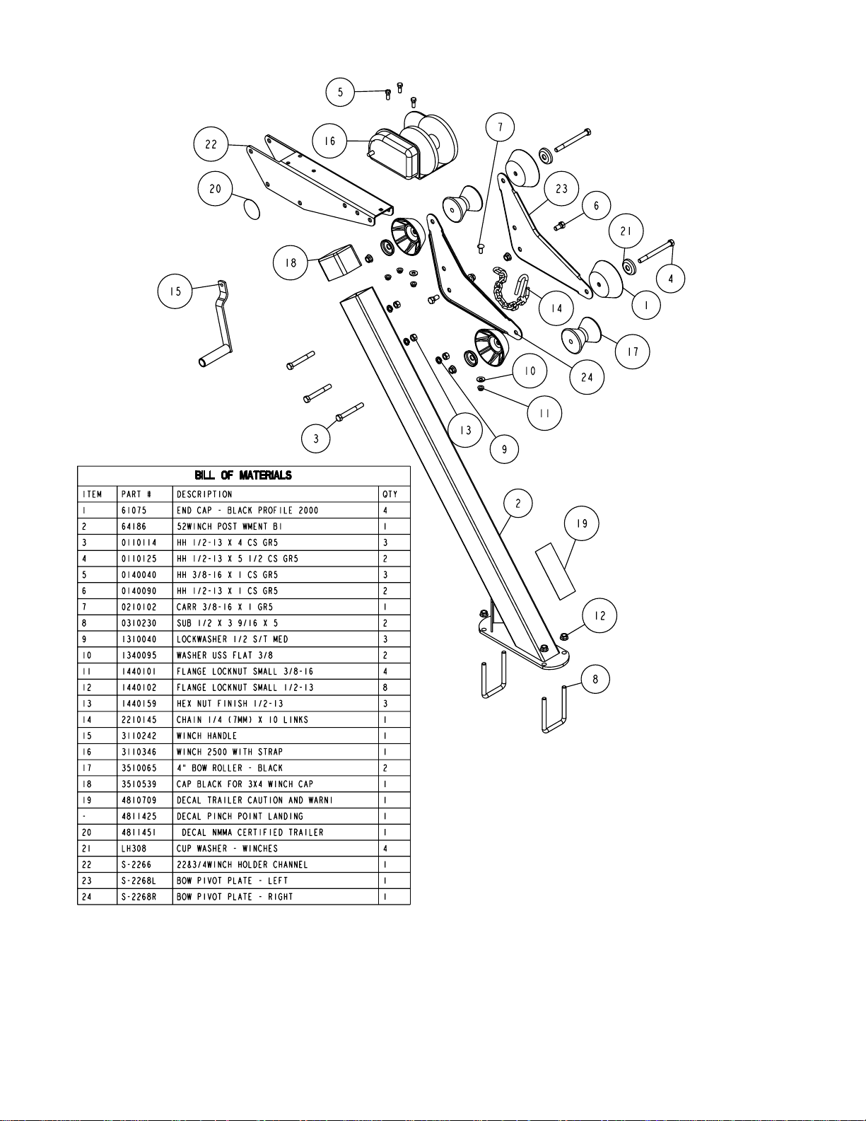
Winch Post Assembly
Mount the winch post assembly to the tongue in a location
that will best fit your boat. Secure the winch post base
weldment (Ref. 2) to the tongue using (2) 1/2” x 3-9/16’ x 5”
U-bolts and hex lock nuts. Attach the winch post tube
weldment to the base just installed with a 1/2” x 4-1/2” hex
bolt and hex lock nut. Tighten only enough to hold the
assembly in position until the boat is positioned on the trailer.
Snap the winch handle on the winch by compressing the
spring loaded clip incorporated in teh handle. Once in
position, release. Handle is secure.
Midwest Industries, Inc. Ida Grove, IA 51445 (800)859-3028 www.shorelandr.com M304016
Page 4
Page 5

Refer to Page 6, 7 & 8 for drawings.
Rocker Arms
Locate the rocker arms (Ref. No. 5 of the chassis schematic).
Note that the center bushing has a grease zerk in it. Position
a rocker arm up into the center channel welded in the center
of the tandem spring bracket so that the grease zerk is
pointing down. Align the holes in the channel with the rocker
arm. Secure in place with a 3/4” x 4-1/2” hex bolt and lock
nut. Tighten. Repeat this process on the other rocker arm
and spring bracket. Grease the rocker at this time by
applying grease through the zerk just discussed.
NOTE: THE GREASE ZERK IS POSITIONED DOWN SO
THAT IT IS ACCESIBLE FOR SERVICING WHEN NEEDED.
Springs
Position the axles so they are properly aligned with the trailer.
The axles must be positioned so that the disc brake calipers
are on the back side of the axle.
Place the springs on the topside of the spring pads welded to
the axle. (See chassis diagram). Note that the hook end of
the spring must be to the rear of the trailer. Place a spring
clamp on the top center of the spring as shown on page 6 &
8. Next place the 1/2” x 6-1/2” U-bolts down over the top of
the spring clamp, spring and axle as shown.
Place the spring and axle U-bolt plate onto the ends of the
two U-bolts just installed on the bottom side of the axle.
Secure in place with 1/2” lock nuts. Thread the nuts onto the
U-bolts but do not tighten securely until the complete unit is
mounted in position on the trailer. Repeat on the other spring
and the other axle.
Axle
Place one of the spring bracket bushings into the rear of the
spring bracket and secure with a 9/16” x 3 1/4” hex bolt and
hex lock nut. Repeat on other spring bracket.
Position the rear axle under the frame, then hook the hook
loop of the spring around the bushings just installed. Note
that if the axle is positioned too low when trying to hook the
springs on the bushings, the hooks will not hook around the
bushings.
Raise the front of the springs up so they align with the rear
hole in the axle rocker arm. Secure in place with 9/16” x
3-1/4” hex bolts and lock nuts.
Next install another spring bracket bushing in the front hole
on the rock arm assembly. Secure with a 9/16” x 3-1/4” hex
bolt and lock nut. Tighten.
Hook the hook end of the springs mounted to the front axle
over the bushing just installed in the rocker arm assembly.
Then swing the front of the spring up and attach to the front
mounting hole in the spring bracket with another 9/16” x
3-1/4” hex bolt and lock nut.
Tighten all axle U-bolts and spring bolts not tightened at this
time.
Brake Line Installation
Sort all of the items in hardware box No. 68140. Locate the
long (90’) brake line and straighten out by uncoiling on a
concrete floor while walking on the line as you uncoil. The
line should be made as straight as possible to assist in
mounting to the axle.
Locate five (5) line clamps and 1/4” self tapping screws
provided in the kit. Hold the line on the backside of the axle
and familiarize yourself on how it needs to be formed to
connect to the brass blocks on the brake calipers. Form the
line so that it can be routed down the back side of the axle
and then over to the brass block on the calipers.
Remove one of the brass plugs from the port in the brass
block on the left brake caliper that best aligns with the routing
of the line. Note also that the bolt holding the brass block to
the caliper can be loosened so that the brass block can be
rotated to better accommodate the angle that the brake line
approaches the block on the caliper. Thread the brake line
fitting into this port to hold the line in position making sure
that the line does not rub or touch the spring. Re-tighten the
bolt in the brass block if it has been loosened to rotate the
block.
Route the line along the back side of the axle and secure to
the axle with the five (5) clamps and self tapping screws.
Note that the axle is pre-drilled for the mounting screws.
Route the brake line over to the brass block on the right brake
caliper. Remove both plugs on the right caliper block. Thread
the other end of the brake line into one of the ports on the
brass block. Thread the 13” brake hose male end into the
other port. Tighten. Position the brass block so that
neither the hose nor the brake line will contact or rub the
spring. Tighten all fittings.
Place the other end of the hose up through the hole provided
in the brake line clip bracket. Secure in place with the hose
clip provided. Item No. 26 in Diagram F.
Repeat this process on the second axle.
Connecting The Two Axles Together and To The Actuator
Locate the brass tee. Thread the male port of the tee into the
female end of the brake hose of the front axle. Tighten. Remove the plastic cap from the end of the frame brake line
coming out of the side frame by the axle. Carefully uncoil the
brake line enough so that it will reach the port of the tee just
threaded into the brake hose. Thread the brake line fitting
into the top port of the tee and tighten.
Locate the 40” brake line tube. Thread one end of the line
into the remaining port of the tee installed in the previous
step. Route the line back to the second axle. Place a coil in
the line to use up any excess line and then connect the other
end of the line into the hose coming from the second axle.
Tighten both fittings. Note that the coil in the line will absorb
the vibration created during towing.
Bleeding the Brake System
Bleed the brake system as specified in the brake manual.
The bleeding process is necessary to remove ALL air
entrapped in the system in order for the brake system to
function properly.
Midwest Industries, Inc. Ida Grove, IA 51445 (800)859-3028 www.shorelandr.com M304016
Page 5
Page 6

Midwest Industries, Inc. Ida Grove, IA 51445 (800)859-3028 www.shorelandr.com M304016
Page 6
Page 7

Tire Size and Carrying Capacity Chart
Tire Size GVWR Carrying Axle
Capacity
ST215/75R14-C 7480 lb. 5800 lb. Brake
Refer to the tire side wall for correct tire
pressure.
Tire And Wheel Assemblies
Mount the tire and wheel assemblies using the
1/2” fine threaded tapered lug nuts provided.
Tighten to 80-90 ft/lb. of torque using the rotation
pattern as shown in the Shore Landr’s Owners
Manual. Re-torque the lug nuts after 50 miles of
driving and then periodically thereafter.
Midwest Industries, Inc. Ida Grove, IA 51445 (800)859-3028 www.shorelandr.com M304016
Page 7
Page 8

Midwest Industries, Inc. Ida Grove, IA 51445 (800)859-3028 www.shorelandr.com M304016
Page 8
Page 9

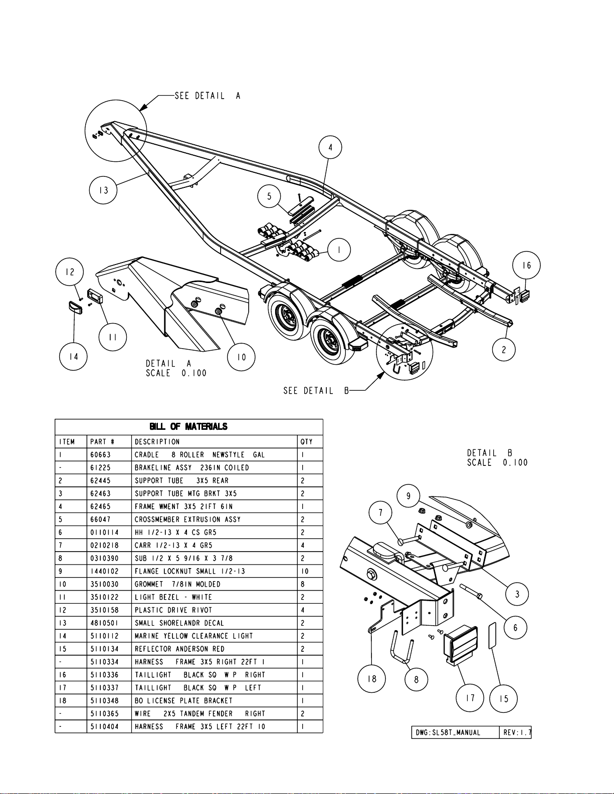
RB Bunk Assembly
Locate the support arms bundle. Place one of the arms into
the factory installed mounting bracket on the rear pivot with
the ends curved up as shown. Secure in the bracket with two
(2) 1/2” x 4” carriage bolts and hex lock nuts. See Detail B,
Page 2. Tighten.
Place one of the bunk assemblies on the end of the support
arms just installed. Line up the top hole in the mounting
bracket with the hole in the support arm and secure with a
1/2” x 4-1/2” hex bolts and hex lock nuts. Tighten. Repeat on
the other end of this support arm. Repeat this complete
process on the other support arm.
Midwest Industries, Inc. Ida Grove, IA 51445 (800)859-3028 www.shorelandr.com M304016
Note that the bunk assemblies have two height adjustments.
The instructions are to install them in the lowest position to
keep the center of gravity as low as possible for towing. If
required for fender clearance, the bunks can be installed in
the raised position by mounting the bunk assemblies to the
bunk support arms using the lower mounting hole.
Page 9
Page 10

Roller Arm Assembly
Locate the support arms bundle. Place one of the arms into
the factory installed mounting bracket on the rear pivot with
the ends curved up as shown. Secure in the bracket with two
(2) 1/2” x 4” carriage bolts and hex lock nuts. See Detail B.
Tighten.
Midwest Industries, Inc. Ida Grove, IA 51445 (800)859-3028 www.shorelandr.com M304016
Place one of the roller assemblies on the end of the support
arms just installed. Line up the hole in the mounting bracket
with the hole in the support arm and secure with a 1/2” x
4-1/2” hex bolts and hex lock nuts. Tighten. Repeat on the
other end of this support arm. Repeat this complete process
on the other support arm.
Page 10
Page 11

Midwest Industries, Inc. Ida Grove, IA 51445 (800)859-3028 www.shorelandr.com M304016
Page 12
Page 12

Midwest Industries, Inc. Ida Grove, IA 51445 (800)859-3028 www.shorelandr.com M304016
Page 12
Page 13

TRAILER ADJUSTMENTS
The adjustment of the trailer to your boat is very important
not only for the trailer, but also the boat. Failure to do so may
lead to potential failure or damage to either the trailer or boat.
Adjust as follows:
Axle Adjustment
The amount of tongue weight on your trailer can be adjusted
as follows:
To lower the tongue weight, adjust the axle assembly
forward. To increase the tongue weight, adjust the axle
assembly backward.
The distance that the axle assembly has to be moved will
vary because it is directly related to the weight and center of
gravity of the boat place on it.
Best towing is achieved when the tongue weight is 5-7% of
the total gross load of the complete unit.
To move the axle assembly, loosen the U-bolts that secure
the assembly to the side frames. Move the assembly to the
desired location then re-tighten the U-bolts.
Note: The brake line and wire harness will need care when
moving the assembly.
Rear Support System
Place the boat on the trailer so that the transom is located at
the rear of the support system. On an RB bunk trailer, the
transom of the boat should be within 1-2” of the end of the
bunk. The center of the rear rollers on the roller rack should
be approximately 4” from the transom. This gives you
maximum support on the transom. The rear pivot is
adjustable forward and backward to assist in adjusting the
trailer to various length boats. This is accomplished by
removing the pivot bolt that attaches the rear pivot to the side
frame and then sliding the assembly to the desired position
and re-attaching with the pivot bolt just removed. The wire
harness for the three-light identification light will have to be
rerouted as well.
RB Bunks
Make sure the bunks are positioned far enough apart to give
your boat as much stability as possible while transporting.
Position the bunks so they are located just to the outside of a
strake that your boat may have. This will help center your
boat and assist when loading. The bunks need to be adjusted
up high enough to keep the keel from resting on the center
pads. A minimum of one to two inches of clearance is
desirable.
When the desired position is determined, tighten only enough
to hold the bunks or rollers from moving while the other
adjustments are being made. Final tightening will be done at
the end of the adjusting process.
Front Support System
RB and Roller
The keel of the boat must rest on the center of the front keel
roller system creating a three-point support system. The keel
roller system is designed to fit most boats without needing
any further adjustment.
Once the boat is positioned on the front roller system, the
stabilizer pads can be adjusted. This is accomplished by
sliding the pad up against the boat bottom by hand. It is not
necessary that they carry much weight. They are designed
to give your boat added stability while being towed. It may be
necessary to adjust the assembly up so that they can be
moved further apart giving additional support. Pull the
assembly away from the boat. Place the U-bolt that holds the
assembly to the cross member in a lower hole in the bracket.
Then push the assembly back against the boat. Tighten in
position.
Winch Post
Now that all other adjustments are complete the winch post
can be adjusted. Slide the winch post base backward on the
tongue until the bow roller comes in contact with the boat.
This bow roller needs to be positioned directly above the boat
bow eye to prevent your boat from moving forward in the
event of a sudden stop.
Loosen the three 1/2” hex bolts that clamp the winch holder
channel to the winch post. Attach the winch strap into the
bow eye and slide the winch holder channel up or down to
the desired position as you crank the winch tight. Once the
bow roller is located just above the bow eye, tighten the three
1/2” hex bolts that clamp the winch holder channel to the
winch post. Tighten the U-bolts that secure the winch post
assembly to the tongue. Attach the bow eye safety chain into
the bow eye of the boat as well. The chain is another level of
protection to keep your boat and trailer together as one unit
in the event of an accident. It may also be used to keep your
boat on the trailer while loading and unloading at the ramp;
especially with a roller trailer.
Adjustments are now complete. Double check your boat for
fit. If desired fit has been achieved, tighten all fasteners that
may have either been left loose or have been loosened to do
the adjusting.
Rollers
Position the roller racks so they are far enough apart to give
your boat stability while transporting. When the desired width
is achieved, move the roller rack system so that one set of
the rollers are just to the outside of a strake if possible. The
rollers need to be adjusted so that you have a minimum of
one to two inches of clearance between the keel of the boat
and the center cross member pads. This will help center the
boat when loading and unloading.
Midwest Industries, Inc. Ida Grove, IA 51445 (800)859-3028 www.shorelandr.com M304016
Re-check all fasteners on the complete trailer to make sure
they are all tight and ready for towing. All fasteners should be
periodically check before towing.
The law requires that the white ground wire on both the tongue
wire harness and vehicle harness be properly grounded to
respective trailer and vehicle frames.
See your ShoreLand’r Owner’s Guide for further technical
information regarding your trailer and its components.
Page 13
Page 14

NOTES
Midwest Industries, Inc. Ida Grove, IA 51445 (800)859-3028 www.shorelandr.com M304016
Page 14
 Loading...