

Page 1
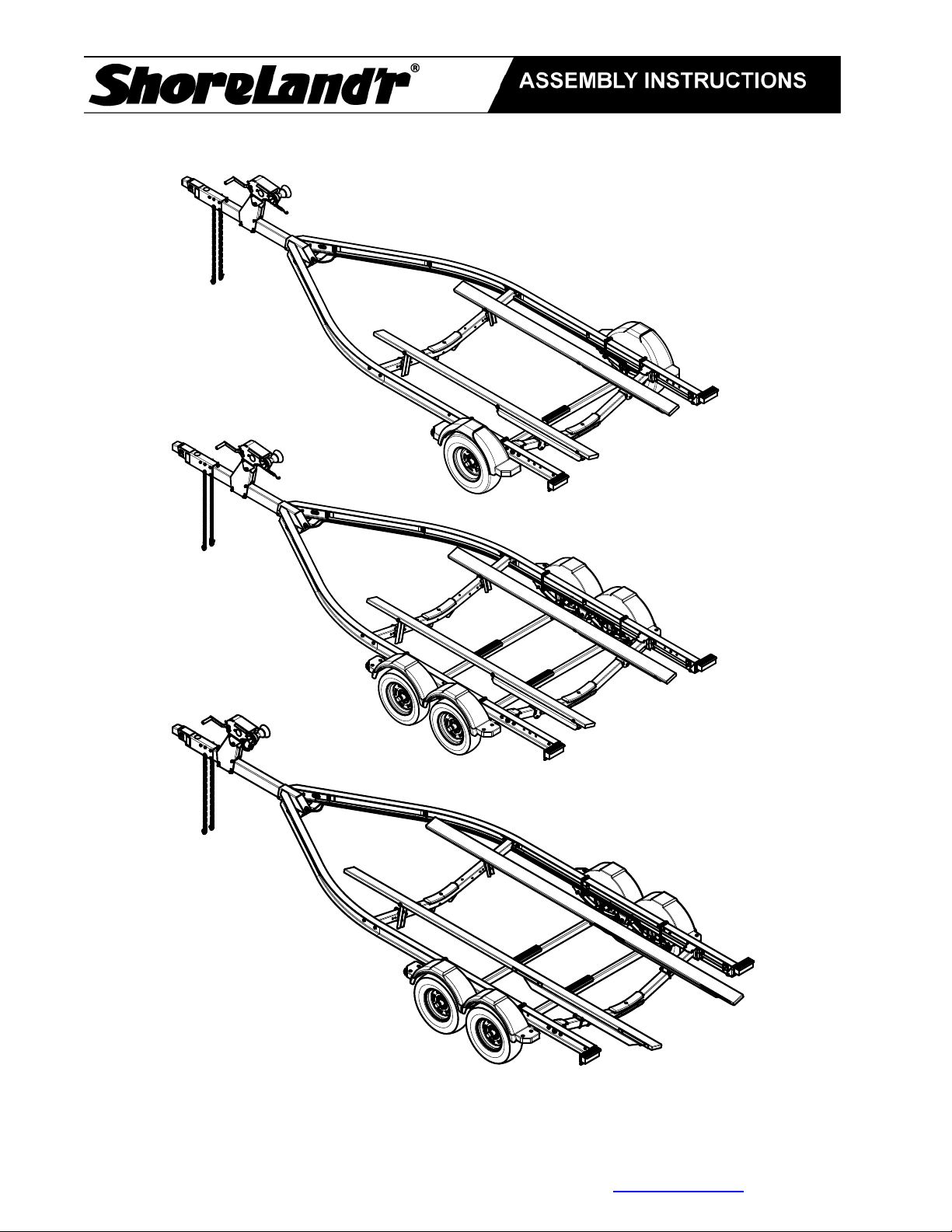
SLB30BAL, SLB40TBAL, SLB40TBBAL, SLB46TBAL, & SLB46TBBAL
ASSEMBLY INSTRUCTIONS
IMPORTANT: All hardware for your trailer is stainless steel. It is important that you use an antiseize material on the bolt threads when assembling to prevent gauling.
Midwest Industries, Inc. Ida Grove, IA 51445 800-859-3028 www.shorelandr.com 0004297
Page 1 of 11 2/09/2011
Page 2
Final Assembly Instructions
p
Remove the small parts from the frame by cutting the bands. Remove the bolt bag and sort all
nuts and bolts by size.
Refer to the following pages for assembly instruction by components.
Reference: Standing at the rear of the trailer will determine the right and left side of the trailer
in the assembly instructions.
The trailer side frames and crossmembers are assembled at the manufacturer. The spring
brackets and fenders are also assembled at the manufacturer.
Tools for Assembly
Wrenches: 9/16, 3/4, 7/8, & 1 1/8
Sockets: 9/16, 3/4, 13/16. & 1 1/8
Tools for connecting brakes:
Wrenches: 7/16, 3/8, 5/8, & 12mm and also a 3/8 nut driver.
Safety Instructions
• Always wear personal protective equipment (safety glasses, gloves, etc) when
assembling and installing components.
• Inspect all fasteners regularly for deterioration and fastener tension. Refer to the
exploded part views for fastener locations
in the appropriate parts manual.
• Replace any and all components that show
deterioration due to wear or misuse before
installing or using your boat trailer.
• Never modify parts and components.
Always replace components with genuine
Shoreland’r replacement parts.
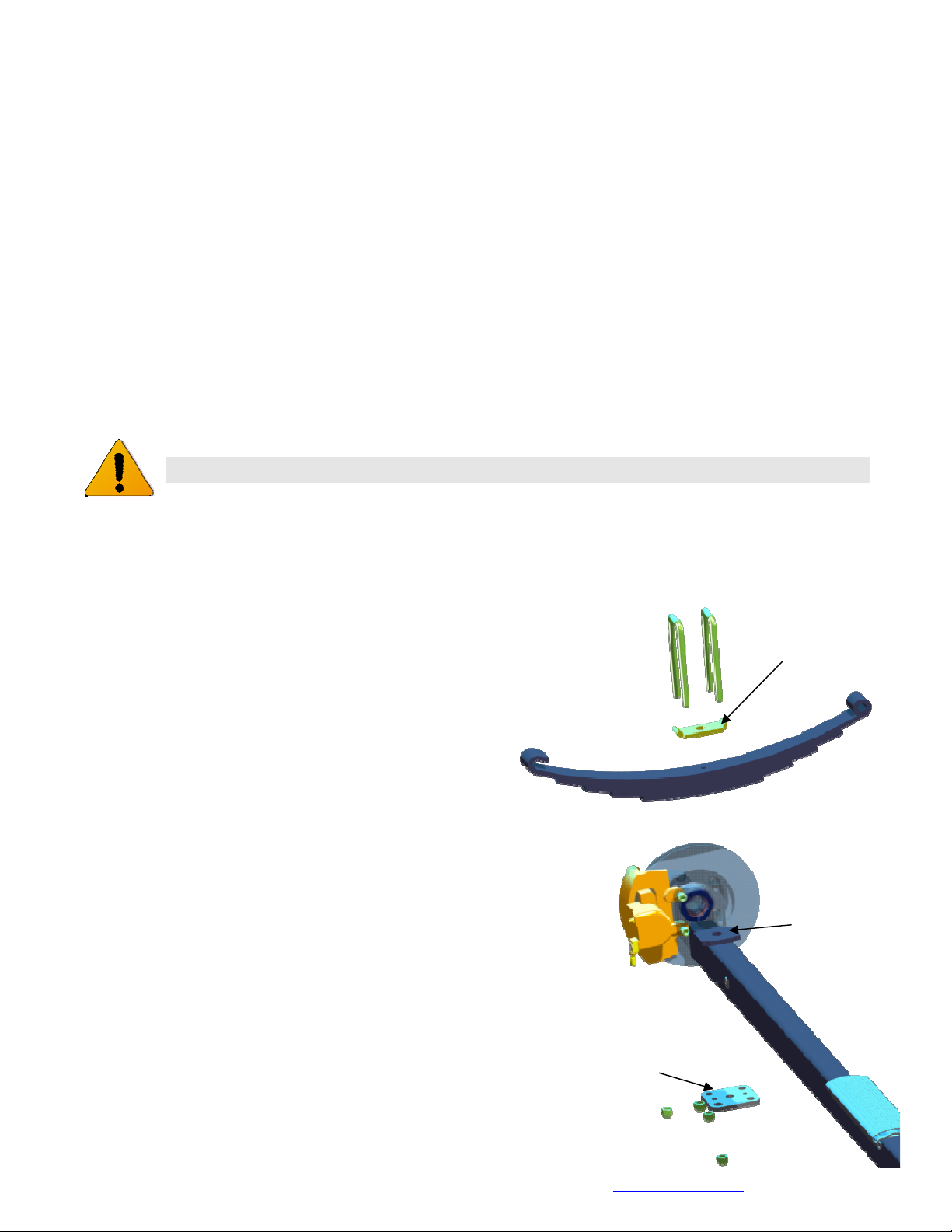
Springs
Position the axle so that it is aligned with the
trailer. Position the brake axle or axles so that the
disc brake calipers are toward the rear of the
trailer.
Place the springs on the topside of the spring
pads welded to the axle. (See chassis diagram)
The hook end of the spring must be mounted to
the rear of the trailer. Place a spring clamp on the
top center of the spring. Place the 1/2” x 6-1/2” Ubolts over the top of the spring clamp, spring and
axle. Place the spring and axle U-bolt plate onto
the ends of the two U-bolts. Secure in place with
1/2” lock nuts. Tighten enough to keep springs
and plates in place until axle /spring assembly is
in proper position.
Spring and
axle U-bolt
plate
Spring
Clam
Spring
Pad
Midwest Industries, Inc. Ida Grove, IA 51445 800-859-3028 www.shorelandr.com 0004297
Page 2 of 11 2/09/2011
Page 3
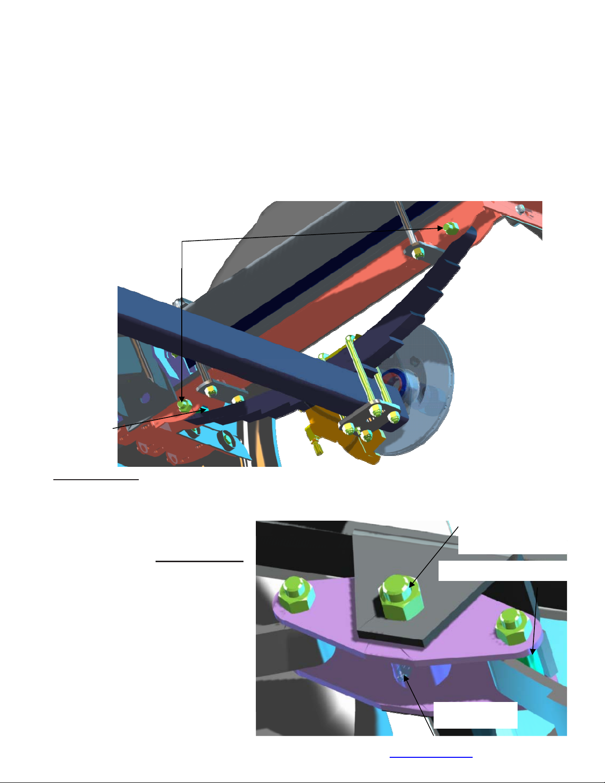
g
Axle
Place a spring bracket bushing (Ref #25) into the rear of the spring bracket and secure with a
9/16” x 3 1/4” hex bolt and hex lock nut. Repeat in other spring bracket. Position the axle under
the frame, hook the hook loop of the spring around the bushings just installed. Note: If the axle
is positioned too low, the hooks will not hook around the bushings.
Raise the front of the springs up so they align with the front hole of the spring bracket. Secure
in place with 9/16” x 3-1/4” hex bolts and lock nuts.
Tighten all axle U-bolts and spring bolts.
9/16” X 3 1/4” Hex
Bolt & Lock Nut
Spring
Bracket
Bushing
TANDEM AXLE
ROCKER ARMS
Locate the rocker arms. Note: Center bushing has a grease zerk in it. Position the rocker
arms up into the center channel
welded in the center of the
tandem spring bracket so that the
3/4” X 4 1/2” Hex
Bolt & Lock Nut
grease zerk is pointing down.
Align the holes in the channel with
Spring Bracket Bushin
the rocker arm. Secure with a 3/4” x
4-1/2” hex bolt and lock nut. Tighten.
Repeat this process on the other
rocker arm and spring bracket.
Grease the rocker, apply grease
through the zerk.
NOTE: The grease zerk is
positioned down so that it is
accessible for servicing.
Grease Zerk
Midwest Industries, Inc. Ida Grove, IA 51445 800-859-3028 www.shorelandr.com 0004297
Page 3 of 11 2/09/2011
Page 4
AXLE
Place one of the spring bracket bushings (Ref. #35) into the rear of the spring bracket and
secure with a 9/16” x 3 1/4” hex bolt and hex lock nut. Repeat in other spring bracket.
Position the rear axle under the frame, then hook the hook loop of the spring around the
bushings just installed. If the axle is positioned too low, the hooks will not hook around the
bushings.
Raise the front of the springs up so they align with the rear hole in the axle rocker arm. Secure
in place with a 9/16” x
3-1/4” hex bolts and lock nuts.
Install another spring bracket bushing in the front hole on the rock arm assembly. Secure with
a 9/16” x 3-1/4” hex bolt and lock nut. Tighten.
Hook the hook end of the springs mounted to the front axle over the bushing in the rocker arm
assembly. Swing the front of the spring up and attach the front mounting hole in the spring
bracket with another 9/16” x 3-1/4” hex bolt and lock nut.
Tighten all axle U-bolts and spring bolts.
Tongue
Remove the tongue from it’s shipping position, reverse it and re-insert it into the front of the
tongue channel. Align the
holes in the tongue with
the holes in the tongue
channel. Secure with a 1/2”
x 4 1/4” hex bolt and 1/2”
lock nut in the front cross
hole. Remove the wire
harness from the rear of
the tongue. Place the wire
harness and the brake line
through the hole in the
tongue cover plate. Secure
the tongue cover plate in
position with a 1/2” x 1-1/2”
hex bolt and 1/2” lock nut.
Tighten. Plug the tongue
wire harness ends into the
1/2” X 4 1/4”
Hex Bolt
frame harnesses by
matching colors and ends.
Push the extra wire into the
rear of the tongue.
1/2” X 1 1/2”
Hex Bolt
Midwest Industries, Inc. Ida Grove, IA 51445 800-859-3028 www.shorelandr.com 0004297
Page 4 of 11 2/09/2011
Page 5

Safety Chains
Place 1/2” x 5” hex bolt through a 1/2” flat washer and the
last link of the safety chains. Insert in the hole (bottom
front of the actuator) on the tongue. Place the second
chain on the same bolt that is extending through the other
side of the tongue. Secure with a 1/2” flat washer and hex
lock nut.
Brake Line
Locate the brass brake line coupling. Remove the plastic
cap and thread the brake hose coming out the rear of the
tongue into one end of the coupling. With the coupling on
the tongue brake hose align these to the brake hose from
the side frame. Once aligned, thread the side frame brake
hose into the other end of the coupling. Tighten both lines
into the coupling. After bleeding the brake system if no
leaks appear slide connections back into the tongue.
Midwest Industries, Inc. Ida Grove, IA 51445 800-859-3028 www.shorelandr.com 0004297
Page 5 of 11 2/09/2011
Page 6

Winch Post Assembly
The height that the
bow eye is located on
your boat will
determine the winch
post length required.
Once this is
determined, attach the
winch base to the
tongue with three 1/2”
x 4-1/4” hex bolts and
lock nuts.
Align the holes in the
Profile 2000 winch
1/2"1/2 X 4 1/2"
Hex Bolts &
Lock Nuts
head mounting
channel with the holes
in the top of the winch
base. Attach the front
of the winch head
Bushing
mounting channel to
the base with a 1/2” x
4-1/2” hex bolt through
1/2” X 4 1/4” Hex
Bolts & Lock Nuts
the hole closest to the
front of the winch
base. Secure with a
lock nut. Do not
tighten.
The winch head can
be rotated either up or
down. Identify the
correct hole
combination to position the bow eye roller just above the bow eye of your boat. Secure in
position by placing the bushing as shown inside the winch base so it aligns with the hole just
identified for the proper adjustment. Insert another 1/2” x 4-1/2” hex bolt through the
determined mounting hole in the mounting channel and winch base making sure the bolt
passes through the bushing.
Secure with a 1/2” lock nut. Tighten all bolts.
Midwest Industries, Inc. Ida Grove, IA 51445 800-859-3028 www.shorelandr.com 0004297
Page 6 of 11 2/09/2011
Page 7

One Axle Brake Installation
Cut the tape securing the brake hose to the axle. Remove the
plastic plug from the bottom port in the brass block on the right
brake caliper. Thread in the male end of the brake hose and
tighten. Repeat the process on the other side of the trailer
removing the plastic cap from the side port on the left caliper.
Insert the threaded end of the brake hose and tighten. Remove
the plastic cap from the end of the frame brake hose. This brake
hose is located coming out of the black plastic tube in the side
frame by the axle. Uncoil the brake hose so that it can be routed
thru the brake line clip bracket. Thread the side frame brake hose
into the side port of the right caliper. Tighten. Place a grommet
around the brake hose and insert in the brake line clip to protect
the frame brake hose. NOTE: Bleeding of the system should be
done through the bleeder on the left caliper.
Fill the actuator reservoir with brake fluid and bleed the line per
the instructions in the Brake Manual. All bleeding of the system
should be done through the bleeder on the left caliper.
For bleeding instructions see the ShoreLand’r Disc Brake Manual.
DUAL AXLE BRAKE INSTALLATION
Cut the tape securing the brake hose to the axle. Remove the plastic plug from the bottom port
in the brass block on the right brake caliper. Thread the brake hose male end into the block
and tighten. Repeat the
process on the other side of the
trailer removing the plastic cap
from the side port on the left
caliper. Insert the threaded end
of the brake hose and tighten.
Attach the male/female brake
hose from the brake kit into the
side port on the brass block on
the right caliper. Attach the
brake hose from the axle to the
spring bracket with the brake
line clip bracket as shown.
Once the brake hose is secured
with the hose clips, locate the
brass tee connector. Screw the
male port of the tee into the
brake line hose. Tighten.
Connect the side frame brake
hose into the top port on the
tee. Connect the two axles
Midwest Industries, Inc. Ida Grove, IA 51445 800-859-3028 www.shorelandr.com 0004297
Page 7 of 11 2/09/2011
Page 8

together using the 42” brake hose. Thread one end of the hose into the remaining port in the
Frame
Brake
Hose
Attaches
Here
brass tee. Route the hose over to and thru the brake line clip above the other axle. Connect
the other end into the side port of the right caliper on the second axle. Place a grommet around
the hose and insert into the brake line clip. To keep excess line up out of the way make a loop
in the 42” line and secure to the side frame with the clips included in the kit.
Fill the actuator reservoir with brake fluid and bleed the line per the instructions in the
ShoreLand’r Disc Brake Manual. Bleeding the system should be done through the bleeder
on the left caliper.
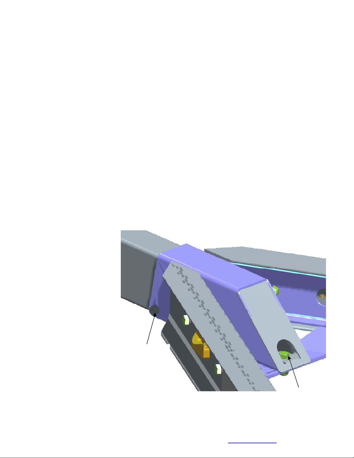
BUNK ASSEMBLY
Locate the two 2 x 6 bunk assemblies. Note that the bunk mounting brackets are assembled at
factory. Place the end with the two brackets towards the rear of the trailer. Place the
assembly
on the equiload bunk arm and secure by placing a 3/8” x 1” hex bolt through the bracket on the
bunk and the ear on each end of the equiload arm. Secure in place using a 3/8” lock nut.
Repeat on the other end of the arm.
Midwest Industries, Inc. Ida Grove, IA 51445 800-859-3028 www.shorelandr.com 0004297
Page 8 of 11 2/09/2011
Page 9

The front bracket is not attached to the bunk because the trailer can be adjusted to two
different lengths. Once the proper
position for the rear cross member is
determined, the front of the bunk can
now be attached to the bracket using
two- No. 10 x 1-1/4” self tapping screws.
The 3/8” bolts can be tightened but not
over tightened because the bunks
should be allowed to rotate slightly to
conform to the boat’s bottom.
Tire and Wheel Assemblies
Mount the tire and wheel assemblies using the 1/2” fine threaded tapered lug nuts provided.
Tighten to 80-90 ft/lb. of torque using the rotation pattern as shown in the ShoreLandr’s
Owners Manual.
Re-torque the lug nuts after 50 miles of driving and then periodically thereafter.
Refer to the tire side wall for correct tire pressure.
Midwest Industries, Inc. Ida Grove, IA 51445 800-859-3028 www.shorelandr.com 0004297
Page 9 of 11 2/09/2011
Page 10

NOTE: All nuts and bolts must be tightened before towing.
TRAILER ADJUSTMENTS
Axle Adjustment
The amount of tongue weight on your trailer can be adjusted as follows: To lower the tongue
weight, adjust the axle assembly forward. To increase the tongue weight, adjust the axle
assembly backward. The distance that the axle assembly has to be moved will vary because it
is directly related to the weight and center of gravity of the boat place on it. Best towing is
achieved when the tongue weight is 5-7% of the total gross load of the complete unit.
NOTE: Brake line and wire harness will need care when moving the assembly.
Rear Support System
Place the boat on the trailer so that the transom is located at the rear of the support system.
On a bunk trailer, the transom of the boat should be within 1-2” of the end of the bunk. This
gives you maximum support on the transom.
The rear cross member is adjustable
forward or backward to allow the trailer to
be adjusted to various length boats. This
is accomplished by removing the pivot bolt
on each end that holds the rear pivot arm
to the side frame and the rear pivot offset
weldments.
Once the rear pivot arm assembly is
removed, remove the two additional bolts
on each side frame that mount the rear pivot offset weldments to the side frame. Move them to
the desired location and remount to the side frames with the bolts just removed. Reposition the
rear pivot arm between the two rear pivot offset weldments just installed. Secure in place using
the two pivot bolts removed earlier. Tighten. The wire harness for the three-light identification
light must be re-positioned where it comes from the black wire harness tubing to eliminate
slack, and sagging of the wiring.
Bunks
The bunks must be positioned far enough apart to give your boat as much stability as possible
while transporting. Position the bunks so they are located just to the outside of the boat’s
strake. This will help center your boat and assist when loading. The bunks need to be adjusted
up high enough to keep the keel from resting on the center pads. A minimum of 1” to 2” of
clearance is desirable.
Winch Post/Bow-eye
Slide the winch post base backward on the tongue until the bow roller comes in contact with
the boat. The bow roller needs to be positioned directly above the boat bow eye to prevent
your boat from moving forward in the event of a sudden stop. It can be moved up or down by
removing the back bolt that mounts the winch head to the base. When this bolt is removed, the
head can be rotated up or down to reach the height required to fit your boat. Once in this
position, align the closest pair of holes in the brackets and reinsert the bolt just removed.
Tighten. Attach the winch strap and crank winch tight. Attach the bow eye safety chain into the
Midwest Industries, Inc. Ida Grove, IA 51445 800-859-3028 www.shorelandr.com 0004297
Page 10 of 11 2/09/2011
Page 11

bow eye of the boat as well. This is just another level of protection to keep your boat and trailer
together as one unit.
Adjustments are now complete.
Double check your boat for fit. If desired fit has been achieved, tighten all fasteners that may
have either been left loose or have been loosened to do the adjusting.
Re-check all fasteners on the complete trailer to make sure they are all tight and ready for
towing. All fasteners should be periodically checked before towing.
See your ShoreLand’r Owner’s Guide for further technical information regarding your trailer
and its components.
Midwest Industries, Inc. Ida Grove, IA 51445 800-859-3028 www.shorelandr.com 0004297
Page 11 of 11 2/09/2011
 Loading...