

Page 1
®
2X3
Bundle Document Reference
How to read your Service Manual:
To identify the model of your trailer please refer to the VIN decal located on the inside of the left side frame at the front
of the trailer.
This Bundle Document Reference Sheet refers to the model identification of your trailer and the components that make
up that particular trailer. Refer to the chart below: Listed are the various components with document numbers listed. The
document number is located in the lower right-hand corner of each service manual sheet. When referencing the different
components of your trailer, please refer to the document number.
When contacting your dealer for service, please refer to the document numbers.
ROLLER
FRAME SUBASSY CHASSIS WINCH ASSY
DOC# DOC# DOC# DOC#
SLB20L 0002885 - - - - - - 0002773 0002760
Color Coating Reference
NOTE: ShoreLand’r offers their product line in either galvanized or painted finish. When ordering parts it is important
that you specify the finish or color you have on your product. The five digit number along with a two digit space _ _,
notes the parts which can be purchased with various finishes. When ordering these items use the five digit prefix and
include the following two digit suffix for proper finish.
Suffix Finish / Color
00 or G Galvanized
01 Arctic White
03 or BK Black
06 or AW Antique White
Tongue Weight Adjustment
Approximate Tongue Weight for Best Towing. Tongue weight too high, move the axle assembly forward. Tongue
weight too low, move the axle assembly backward. Tongue weight should be 5-7% of total gross weight of both boat and
trailer combined.
Cautions/Warnings
The law requires that the white ground wire on the both the tongue wire harness and the vehicle harness be
properly grounded to the respective trailer and vehicle frames.
Double check all nuts and bolts ---- tighten before towing.
Midwest Industries, Inc. Ida Grove, IA 51445 (800)859-3028 www.shorelandr.com 0002766
Page 2

Page 3
®
SLB20L
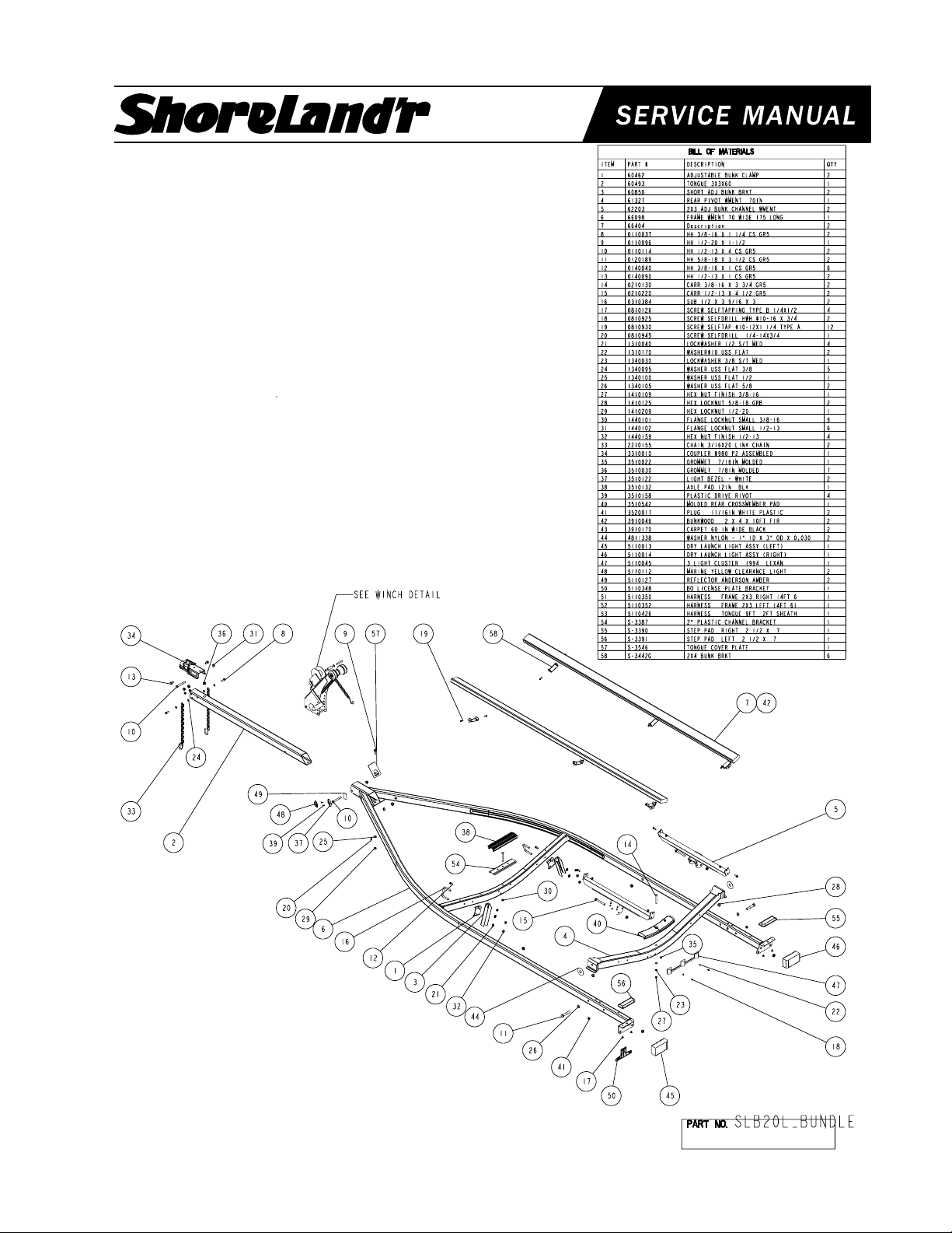
Final Assembly Instructions
Remove the small parts from the frame by cutting the
bands. Remove the bolt bag and sort all nuts and bolts by
size.
Tongue:
Remove the tongue assembly from the frame bundle and
install into the tongue channel and secure with a 1/2” X 4”
hex bolt in the side of the tongue and tongue channel.
Secure with a 1/2” flange lock nut.
Place the tongue cover over the rear of the tongue and
tongue channel and secure with a 1/2” X 1-1/2” hex bolt,
1/2” flat washer and 1/2” hex nut.
Tongue Wires:
Install the tongue wire harness through the top forward
wire hole and exit the rear of the tongue channel on the
frame. Install grommets and plug the tongue wire into the
frame harness by color.
#0002760
NOTE: Standard tongue is shown.
See Document 0002785
for the longer tongue option.
Midwest Industries, Inc. Ida Grove, IA 51445 (800)859-3028 www.shorelandr.com 0002855
Page 4

Safety Chain:
Insert a 3/8” X 1-1/4” hex bolt with a 3/8” flat washer and
safety chain through the lower hole on the front of the
tongue. Secure with a 3/8” flat washer and 3/8” flange lock
nut. Repeat the procedure on the opposite side of the
tongue.
would best fit your watercraft. Secure with 1/2” X 3-9/16” X
3” square u-bolts and 1/2” flange lock nuts.
Mount the adjustable bunk channel weldment to the rear
pivot in a location that best fits your watercraft using a 1/2”
X 4-1/2” hex bolt and 1/2” flange lock nut per adjustable
bunk channel weldment.
Coupler:
Mount the coupler onto the tongue with one (1) 1/2” X 4”
hex bolt into the rear of the couplerand tongue and using
two (2) 1/2” X 1” hex bolts into the two (2) front holes on
the coupler and tongue. Secure with 1/2” flange lock nuts.
Bunks:
Mount the adjustable bunk brackets with the adjustable
bunk clamps to the front crossmember in a location that
Secure the bunk assemblies to the adjustable bunk
brackets on the front crossmember using 3/8” X 1” hex
bolts and 3/8” flange lock nuts.
Secure bunk assemblies to the adjustable bunk channel
weldments on the rear pivot using 3/8” X 1” hex bolts and
3/8” flange lock nuts.
DO NOT OVER TIGHTEN - the bunks must pivot freely
to conform to the boats hull.
Page 5

®
20 Chassis
Midwest Industries, Inc. Ida Grove, IA 51445 (800)859-3028 www.shorelandr.com 0002773
Page 6

Place one of the spring bushings (Ref.#33) into the rear of the
spring bracket (Ref.#5) and secure with a 9/16” X 3-1/4” hex bolt
(Ref.#6) and 9/16” hex lock nut (Ref.#17). Repeat on the other
side. Position the axle (Ref.#2) under the frame, then hook the
spring loop around the bushing just installed. Raise the axle
assembly up so the front of the springs (Ref.#30) line up with the
front spring bracket hole. Insert the other two (2) 9/16” X 3-1/4” hex
bolts and 9/16” hex lock nuts. Tighten all nuts and bolts, but do not
over tighten. Allow the spring room enough to move.
Mount the tires and rim assemblies (Ref.#23) using 80-90 ft. lbs.
tongue on lug nuts (Ref.#14) using proper tightening procedures.
Tire Size & Carrying Capacity Chart
Tire Load Carrying
Size Range Capacity
ST175/80R13 B 1100 lbs. per/tire
Refer to the tire side wall for the correct tire pressure.
Page 7

®
Winch Assembly - 60602--
Secure the winch post to the tongue with three (3) 3/8” X 4” hex
bolts and 3/8” flange lock nuts. Mount the winch handle to the
winch using the special nut provided. Tighten the winch post in a
location that best fits your water craft.
Winch Post Adjustment:
Once the boat is postioned on the trailer, adjust the winch post to
the boat. Adjust the bow stop bracket so that the rubber bow stop
is just above the bow eye.
Midwest Industries, Inc. Ida Grove, IA 51445 (800)859-3028 www.shorelandr.com 0002760
Page 8

Page 9

®
2X3 Long Tongue Option (S-TL)
REF# PART# DESCRIPTION QTY
1 62091-- TONGUE 3X3X60 ...................................... 1
2 0110037 HH 3/8-16 X 1 1/4 CS GR5 ....................... 2
3 0110114 HH 1/2-13 X 4 CS GR5 ............................. 1
4 0140090 HH 1/2-13 X 1 CS GR5 ............................. 2
5 0810925 SCREW SELFDRILL HWH #10-16 X 3/4 . 4
6 1340095 WASHER USS FLAT 3/8 ........................... 4
7 1440101 FLANGE LOCKNUT SMALL 3/8-16 .......... 2
8 1440102 FLANGE LOCKNUT SMALL 1/2-13 .......... 3
9 2210155 CHAIN 3/16X20 LINK CHAIN ................... 2
10 3100010 COUPLER #980 P2 ASSEMBLED ............ 1
11 3510030 GROMMET 7/8IN MOLDED .................... 1
12 5110127 REFLECTOR ANDERSON AMBER ......... 2
13 5110318 9' TONGUE HARNESS ............................. 1
14 5110394 DO RAY JUMPER WIRE 24 IN................. 1
15 5110456 LIGHT AMBER SIDE MARKER 36IN WI. 2
Tongue:
Remove the tongue assembly from the frame bundle and
install into the tongue channel and secure with a 1/2” X 4”
hex bolt in the side of the tongue and tongue channel.
Secure with a 1/2” flange lock nut.
Place the tongue cover over the rear of the tongue and
tongue channel and secure with a 1/2” X 1-1/2” hex bolt,
1/2” flat washer and 1/2” hex nut.
Tongue Wires:
Install the tongue wire harness through the top forward
wire hole and exit the rear of the tongue channel on the
frame. Install grommets and plug the tongue wire into the
frame harness by color.
Safety Chain:
Insert a 3/8” X 1-1/4” hex bolt with a 3/8” flat washer and
safety chain through the lower hole on the front of the
tongue. Secure with a 3/8” flat washer and 3/8” flange lock
nut. Repeat the procedure on the opposite side of the
tongue.
Coupler:
Mount the coupler onto the tongue with one (1) 1/2” X 4”
hex bolt into the rear of the couplerand tongue and using
two (2) 1/2” X 1” hex bolts into the two (2) front holes on
the coupler and tongue. Secure with 1/2” flange lock nuts.
Made in the USA Midwest Industries, Inc. Ida Grove, IA 51445 (800)859-3028 0002785
www.shorelandr.com
REV - 7/06/00
Page 10

2X3 Long Tongue W/Brakes Option (S-TL)
REF# PART# DESCRIPTION QTY
1 61214 BRAKELINE ASSY 88IN ......................... 1
2 62091-- TONGUE 3X3X60 ..................................... 1
3 65595-- OUTER HOUSING - UFP ACTUATOR ... 1
4 0110114 HH 1/2-13 X 4 CS GR5 ............................ 3
5 0110120 HH 1/2-13 X 5 CS GR5 ............................ 1
6 0810925 SCREW SELFDRILL HWH #10-16 X 3/4 4
7 1440102 FLANGE LOCKNUT SMALL 1/2-13 ......... 4
8 2220272 CHAIN 8/0 MACH CHAIN 37" W/837 ...... 2
9 3510030 GROMMET 7/8IN MOLDED ................... 1
10 3820060 ACTUATOR INNER.................................. 1
11 5110127 REFLECTOR ANDERSON AMBER ........ 2
12 5110318 9' TONGUE HARNESS ............................ 1
13 5110394 DO RAY JUMPER WIRE 24 IN................ 1
14 5110456 LIGHT AMBER SIDE MARKER 36IN WI . 2
15 7010168 CAP PLASTIC OUTER MEMBER 2” DI .. 1
Actuator & Safety Chain:
Slide the actuator (Ref.#10) into the actuator housing unit
(Ref.#3) and secure with two pins and snap rings provided
with the actuator. Secure the actuator-housing unit to the
front of the tongue using three-(3) ½” X 4” hex bolts and
½” flange lock nuts. Using a ½” X 5” hex bolt on lower
right mounting hole on tongue, secure the safety chain.
Place a ½” flat washer on ½” X 5” hex bolt followed by one
safety chain and insert into actuator housing unit and
tongue. Place the second safety chain on the bolt followed
by a ½” flat washer and ½” flange lock nut. Tighten.
Brakes:
Refer to the brake manual for service and maintenance.
 Loading...