

Page 1
®
SLB150TAL
Aluminum Trailer - 15000 Bunk
SLB150TAL Alum Trailer w/Bunk
3310056 Jack 2000 lb. Drop Leg w/Mtg Hdwe
*LT235/85R16D Tire /Galv Mod Rim
5110578 Titan II Actuator w/Components
62340 Lit Packet - Trailers
6627100 Frame Bundle - SLB150TAL
6813500 Hdwe Box for Tandem/Tri Alum
68141 Brake Kit 8” Alum TriAxle
*Check with your dealer/customer service representative for current tire/rim assembly
part number.
Midwest Industries, Inc. Ida Grove, IA 51445 800.859.3028 www.shorelandr.com 0004000
Page 1 09/15/2008
Tire Size and Carrying Capacity Chart
Tire Size ............................LT235/85R16D
GVWR ...............................18,252 lb.
Carrying Capacity ............15,000 lb.
Axle ...................................Tri-Axle - Brakes
Refer to the tire side wall for correct tire pressure.
Page 2
Diagram A
Midwest Industries, Inc. Ida Grove, IA 51445 800.859.3028 www.shorelandr.com 0004000
Page 2 09/15/2008
Page 3

Breakaway Switch
Diagram B
Tongue:
Slide the tongue into the tongue channel weldment on front crossmember. Secure the tongue with a 5/8” X 7” stainless steel hex bolt,
5/8” stainless steel at washer and 5/8” stainless steel hex lock nut
with nylon insert.
Secure the tongue to the tongue plate on the frame using two (2)
5/8” X 5-3/4” X 6-1/2” square u-bolts and four (4) 5/8” stainless
steel hex lock nut with nylon inserts.
Coupler / Safety Chain:
Mount the coupler onto the tongue (matching the hole pattern) using four (4) 5/8” X 1-3/4” stainless steel hex bolts and four (4) 5/8”
stainless steel hex lock nuts with nylon inserts.
Mount the safety chains to the front of the tongue using a 1/2” X
1-1/2” stainless steel hex bolts, followed by a 1/2” stainless steel at
washer and safety chain. Secure this assembly on the inside of the
tongue using a 1/2” stainless steel hex lock nut with nylon insert.
Repeat the above instructions on the other side of the tongue.
Midwest Industries, Inc. Ida Grove, IA 51445 800.859.3028 www.shorelandr.com 0004000
Page 3 09/15/2008
Page 4
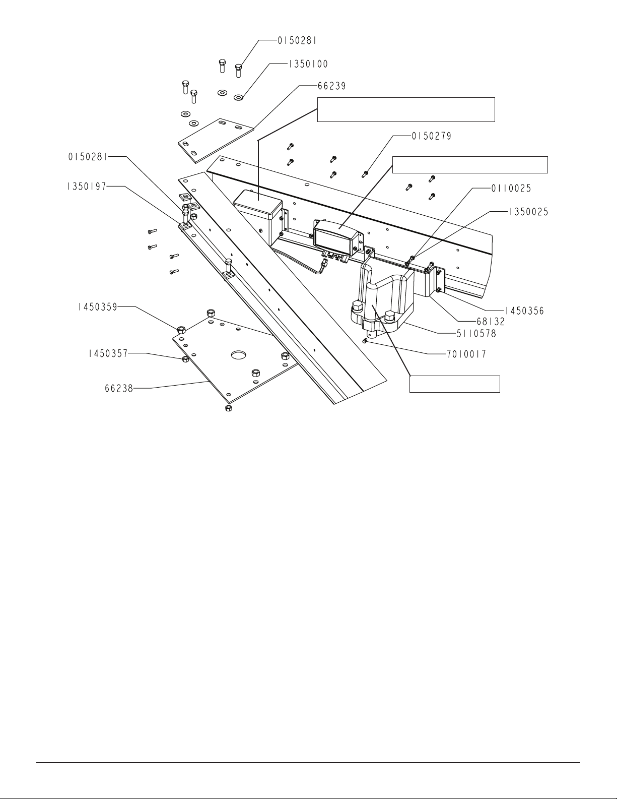
Diagram D
Battery Boxes
(one mouted to each side frame)
SD Control Module
Actuator
Wiring Instructions
The attaching hardware for the actuator and the battery boxes on
the aluminum trailers is stainless steel. They require that you use
the appropriate size nuts with the nylon inserts.
• Open the box containing all the items required for installing the
electric over hydraulic brake system.
The wire harness for the brake system and lighting is pre-wired with
mating plugs to simplify the connection process. Also the rear portion of the tongue harness has been installed at the factory.
• Place the wire harness supplied in the box into the front of the
tongue so the large round 7 prong plug remains out the front of the
tongue.
• Pull the wire harness into the tongue and route it out the top of the
tongue through the large hole provided.
• Pull all of the wire ends with bullet plugs and mating plugs out
the hole in the top of the tongue including the white wire with the
grounding ring.
• Connect the single bullet ends of the brown, yellow and green
wires of this wire harness to the mating plugs of the factory installed
wire harness for the rear section of the tongue. These wires are
extending out the hole in the top of the tongue and are taped there
during shipping.
• Once attached these wires can be placed down inside the
tongue.
Midwest Industries, Inc. Ida Grove, IA 51445 800.859.3028 www.shorelandr.com 0004000
Page 4 09/15/2008
• The white wire with the grounding ring will be attached later
when the battery boxes are fastened to the side frames. This white
grounding wire is used only for a grounding system for the trailer
lights and has nothing to do with the brake system which has its
own grounding system pre-wired in the harness.
• Locate the two wire plugs: brown and yellow, and brown and
green at the rear of the tongue. Mate these plugs with those of
the side frame wire harnesses and plug together making sure they
have a good connection. Place any excess wiring inside the rear
of the tongue.
• See Diagram B. Locate the breakaway switch that is already attached and wired into the main wire harness just installed in the
front of the tongue. Position it so it is approximately 3” behind the
coupler. Mark the mounting hole location. Drill a 13/64” pilot hole
in the tongue. Insert the ¼” self-drilling screw provided and secure
in place.
Battery Box Installation Instructions
Locate the battery boxes. Note that there are two battery boxes and
two batteries. They are both required to power the brake system in
the event of a disconnect from the tow vehicle.
1. Attach the two battery boxes to the front of the side frames mating the holes in the battery boxes with those pre-drilled in the side
frames. Mount them to the side frames using ¼” x 1” carriage bolts
and ¼” lock nuts. Place the grounding ring attached to the end
of the white ground wire to one of the screws before the nut is
threaded on. Once all bolts are installed, tighten.
Page 5

SD Control Module Mounting Instructions
Locate the SD control module. Position the SD control module so
the mounting holes in it align with the holes pre-drilled in the side
frame. Secure the SD control module to the side frame with two- ¼”
x 1” carriage bolts and hex nuts. Tighten.
Batteries
1. Place the batteries in the battery boxes. Remove the protective
covers from the battery terminals.
Locate the battery wire harness supplied in the kit. Connect it to the
batteries by connecting the wire harness spades with the red coating to the positive post and the white or black wire to the negative
post of the battery.
2. Route the wire harness from one battery to the other and then
over to the SD control module. Place on the battery box covers.
Bleeding of the Hydraulic Brake System
1. Check to make sure brake uid has been added to the system
as recommended above.
2. Pull the cable on the breakaway switch installed just behind the
coupler. This will pull a pin out the switch automatically activating
the switch. The actuator will now draw its power from the batteries
installed on the trailer. The actuator will continue to run until the batteries are drained. You will be able to hear the actuator motor run.
3. The proper procedure for bleeding the brake system is to start at
the caliper that is the greatest distance from the actuator. Loosen
the bleeder screw and allow the air to escape from the system until
brake uid starts to ow. Allow it to ow until the brake uid being
expelled is free of any air bubbles entrapped in the lines. Attaching
a clear hose on the bleeder screw will make the air bubbles more
visible during the bleeding process.
3. Attach the battery wire harness to the mating molded plug of the
SD control module. Snap together to hold in place.
Electric Over Hydraulic Actuator Installation
1. Locate the brake actuator Place one each 5/16” lock washer on
the three 5/16” x 1” hex bolts. Attach the brake actuator to the actuator offset bracket with three 5/16” x 1” hex bolts. Tighten. Attach
this assembly to the side frame with four 1/4" x 1" hex bolt and lock
nuts. Tighten.
Note that the SD control module should be located between the
hydraulic actuator and the front of the trailer frame.
2. Snap the mating plugs from the wire harness to the respective
mating plugs from both the SD control box and the actuator according to the instructions provided with the electric over hydraulic kit.
See the wiring schematic on page 20 of the manual provided with
the actuator. Make sure they are completely snapped together and
locked to assure a positive connection.
Brake Line Tubing Connection
1. Locate the brake line installed at the factory and is routed to the
newly installed actuator.
2. Carefully bend and route the tubing with smooth round curves
over to the port in the actuator.
3. Thread the brass brake line elbow tting into the actuator port if
not already installed.
4. Thread the frame brake line into the brass elbow in the port of the
actuator shown. Tighten.
Close the bleeder screw and tighten.
4. Check the reservoir uid level to make sure that the actuator
does not run low on uid during the bleeding process. Rell if nec-
essary. There is a possibility that more air can be introduced into
the system if the uid level is not kept sufcient in the reservoir.
5. Repeat the process used in step three on the caliper that is the
next greatest distance from the actuator. Continue until all of the
brake calipers have been bled.
6. Once the system is bled, When all air is removed, close the
bleeder screw. Push the pin back into the breakaway switch. This
will stop the actuator motor.
7. Rell the reservoir with uid replacing any that may have been
used during the bleeding process.
8. Test the brake system to see if it is bled properly. If brakes function properly the bleeding process is complete. If they do not operate properly, repeat the above steps and test again.
9. Brake uid levels in the reservoir should be checked occasionally to make sure your brake system never runs out of brake uid.
See the Titan BrakeRite Actuator Installation and Instruction
Manual for further information and operating instructions.
In- Cab Controller
Locate the In-cab controller supplied with the kit. Remove the instructions and install the unit in the tow vehicle using the instructions supplied.
Filling the System with Brake Fluid
Fill the reservoir on the actuator with an Arctic-SAEJ1702 or
SAEJ1703 brake uid or a uid that is comparable. Remove one
of the reservoir caps located on the actuator. Only one cap has
to be removed. Add uid until the reservoir is full. Bleed the brake
Always test the brake system at slow speeds each time you start
towing to make sure the brake system is functioning properly.
Should you experience a situation where you do not have brakes
or they are malfunctioning, see your local ShoreLand’r dealer immediately to rectify the problems.
system following the procedure for bleeding the brakes. It may be
necessary to add uid to the reservoir during the bleeding process.
Once the system is completely bled, rell the reservoir. Replace
the cap and tighten to seal out any moisture that may enter during
normal use.
Midwest Industries, Inc. Ida Grove, IA 51445 800.859.3028 www.shorelandr.com 0004000
Page 5 09/15/2008
Page 6

Diagram C
Winch Assembly:
Refer to page ? for winch parts diagram.
The winch post assembly comes factory assembled and ready to
mount on the tongue. Position the winch assembly on the tongue
in a location that would best t your watercraft. Using two (2) 5/8” X
5-3/4” X 6-3/4” stainless steel square u-bolts, secure the winch assembly to the tongue. Tighten with four (4) 5/8” stainless steel lock
nuts so that the winch assembly will not slide on tongue. Set the
other mounting plate in position and secure it using two (2) 5/8” X
5-3/4” X 6-3/4” stainless steel square u-bolts and four (4) 5/8” stainless steel lock nuts. Refer to winch adjustments on page ?.
Jack:
Remove the hardware bag provided by the jack manufacturer and
take out the mounting plates. From hardware bag (66270), take out
four (4) 3/8” X 6” stainless steel hex bolts and four (4) 3/8” stainless
steel lock nuts with nylon inserts, Position the jack on the tongue
in a location that best ts your watercraft. Secure with the stainless
steel hardware. The remaining hardware bag that was removed
from the jack may be discarded.
Midwest Industries, Inc. Ida Grove, IA 51445 800.859.3028 www.shorelandr.com 0004000
Page 6 09/15/2008
Page 7

Refer to your ShoreLand’r Owner’s
Guide and other decals on trailer for
additional information.
SAFETY INSTRUCTIONS
4810709
Proper tongue weight must be maintained.
Rev C 8/28/06
Before towing, check the following to ensure
that:
1. All parts, bolts, nuts and wheel lug nuts
are tight.
2. Tie downs, winch strap and bow-eye
safety chain are secure.
3. Tires are inflated to manufacturer’s
standards. (See tire sidewall)
4. Wheel bearings have adequate grease.
5. Trailer coupler and coupler ball are the
same size.
6. Coupler is properly attached and
secured to coupler ball.
7. Trailer safety chains are crossed under
the tongue and attached to towing
vehicle.
8. All lights are operational. Note: It is
recommended that the trailer lights be
disconnected before backing into the
water.
9. Trailer tongue jack is in up or travel
position.
10. Hitch ball has a rating that is equal to or
greater than the coupler or actuator
GVWR.
11. All wheel lug nuts must be tightened to a
minimum torque rating of 85 ft/lb.
12. Lug nuts must be re-torqued after the
first 50 miles, then periodically thereafter.
4810709 REV 8-06.ai 8/28/2006 7:29:33 AM
Midwest Industries, Inc. Ida Grove, IA 51445 800.859.3028 www.shorelandr.com 0004000
Page 7 09/15/2008
Page 8

Diagram E
Midwest Industries, Inc. Ida Grove, IA 51445 800.859.3028 www.shorelandr.com 0004000
Page 8 09/15/2008
Page 9

Midwest Industries, Inc. Ida Grove, IA 51445 800.859.3028 www.shorelandr.com 0004000
Page 9 09/15/2008
Page 10

Rocker Bushings:
Install the 3/4” ID X 1” OD X 1-1/2” bronze bushings into the inside
the rocker matching the middle and rear hole patterns. The middle
rocker bushing must be secured with a 3/4” X 5-1/2” stainless steel
hex bolt through the rocker, bushing and the middle shackle on the
spring bracket. Tighten using a 3/4” stainless steel hex lock nut with
nylon insert. The front rocker bushing must be secured with a 9/16”
X 3-3/4” stainless steel hex bolt and 9/16” stainless steel hex lock
nut with nylon insert. Repeat this procedure on the other rocker on
the opposite side of the trailer.
Spring Bracket Bushings:
Install the spring bracket bushing into the spring support channel.
This assembly is then inserted into the rear spring bracket shackle
and secured with a 9/16” X 4-1/2” stainless steel hex bolt and 9/16”
stainless steel hex lock nut with nylon insert. Repeat this procedure
on the other spring bracket on the opposite side of the trailer.
Axle:
First Axle Installation:
Align the eye of the spring on the rst axle with the hole provided in
the spring bracket. From the outside in, insert a 9/16” x 3 ¾” hex
bolt through the spring bracket and the eye of the spring. Secure
with a 9/16” hex lock nut.
Raise the rear hook end of the spring and axle assembly up so it
is up inside the rocker bogie. Secure in place by placing a 9/16” x
3 ¾” hex bolt through the hole in the rocker bogie just below the
spring leaf. Secure with a 9/16” lock nut.
Second Axle Installation
Align the eye of the spring on the second axle with the hole provided in the rear of the rocker bogie. From the outside in, insert a
9/16” x 3 ¾” hex bolt through the rocker bogie and the eye of the
spring. Secure with a 9/16” hex lock nut.
routed down the back side of the axle and then over to the brass
block on the calipers.
Remove the lower brass plug from the port in the brass block on
the left brake caliper. Note also that the bolt holding the brass
block to the caliper can be loosened so that the brass block can
be rotated to better accommodate the angle that the brake line
approaches the block on the caliper. Thread the brake line
tting into this port to hold the line in position making sure
that the line does not rub or touch the spring. Re-tighten the
bolt in the brass block if it has been loosened to rotate the block.
Route the line along the back side of the axle and secure to
the axle with the ve (5) clamps and self tapping screws.
Note that the axle is pre-drilled for the mounting screws.
Route the brake line over to the brass block on the right brake
caliper. Remove both plugs on the right caliper block. Thread the
other end of the brake line into the bottom port on the brass block.
Thread the 13” brake hose male end into the other port. Tighten.
Position the brass block so that neither the hose nor the brake line
will contact or rub the spring.
Tighten all ttings.
Place the other end of the hose up through the hole provided in
the brake line clip bracket. Secure in place with the hose clip provided.
Repeat this process on the second and third axles.
Connecting the Three Axles Together
Locate the two brass tees. Thread the male port of the tees into the
female end of the 13” brake hoses running up from the axles just
installed on the front and second axles. Tighten.
Raise the rear hook end of the spring and axle assembly up so it
is up inside the rocker bogie. Secure in place by placing a 9/16” x
3 ¾” hex bolt through the hole in the rocker bogie just below the
spring leaf. Secure with a 9/16” lock nut.
For installtion of the rear axle:
Align the eye of the spring on the third axle with the hole provided
in the rear of the rocker bogie holding the rear of the second axle.
From the outside in, insert a 9/16” x 3 ¾” hex bolt through the rocker
bogie and the eye of the spring. Secure with a 9/16” hex lock nut.
Raise the rear hook end of the springs on the third axle up into the
spring bracket. Place a spring bushing above the hook leaf of the
spring located inside the spring bracket channel. Secure the spring
in the spring bracket by placing a spring support channel under the
spring. Insert a 9/16” x 4-3/4” hex bolt from the outside-in through
the spring support channel, spring bracket and then through the
spring bushing just placed above the hook spring leaf. Secure using a 9/16” lock nut. Repeat on the other spring.
Brake Line Installation
Sort all of the items in hardware box No. 68141. Locate the long
(90’) brake lines and straighten out by uncoiling on a concrete
oor while walking on the line as you uncoil. The line should be
made as straight as possible to assist in mounting to the axle.
Locate ve (5) line clamps and 1/4” self tapping screws provided
in the kit. Hold the line on the backside of the axle and familiarize
yourself on how it needs to be formed to connect to the brass
blocks on the brake calipers. Form the line so that it can be
Remove the plastic cap from the end of the frame brake line coming out of the side frame by the axle. Carefully uncoil the brake line
enough so that it will reach the port of the tee just threaded into the
brake hose. Thread the brake line tting into the top port of the tee
installed on the front axle and tighten.
NOTE: The hook end of the springs must be installed in the same
direction, to the rear of the of the trailer - on both axles!
Brakes:
Refer to the brake manual for service and maintenance.
Tire/Rim Assemblies:
Mount the tire and wheel assemblies using the 1/2” ne threaded
tapered lug nuts provided. Tighten to 85-130 ft./lb. torque using the
rotation pattern as shown in the ShoreLandr’s Owners Manual.
Re-torque the lug nuts after 50 miles driving and then periodically
thereafter.
Front Bunk:
Mount the bunk bracket weldment into the pivot base weldment
using a 5/8” X 4-1/2” stainless steel hex head bolt and secure with
a 5/8” stainless steel hex lock nut with nylon insert. Mount the bunk
assembly onto the bunk bracket weldment using two (2) 1/2” X
1-1/2” stainless steel hex bolts and secure with two (2) 1/2” stainless steel hex lock nuts with nylon insert. Repeat
this procedure on the opposite side of the trailer.
Midwest Industries, Inc. Ida Grove, IA 51445 800.859.3028 www.shorelandr.com 0004000
Page 10 09/15/2008
Page 11

Diagram F
Rear Bunk:
Mount the bunk bracket weldment into the pivot base weldment
using a 5/8” X 4-1/2” stainless steel hex head bolt and secure with
a 5/8” stainless steel hex lock nut with nylon insert. Mount the bunk
assembly onto the bunk bracket weldment using two (2) 1/2” X
1-1/2” stainless steel hex bolts and secure with a two (2) 1/2” stainless steel hex lock nuts with nylon inserts. Repeat this procedure
on the opposite side of the trailer.
Wiring:
Run the wiring from the frame outlet to the bunk bracket weldment
and run throught the inside and exit out the end of the bunk bracket
weldment. The ex conduit located in the hardware box will be used
to cover the frame wire harness before it enters the bunk bracket
weldment. Install grommets over 3/8” ex conduit in wire holes on
bunk bracket weldment. Using wire ties secure the ex conduit to
the crossmember. Leave the wire until after the mounting of the
taillights on the bunk brackets tube.
Taillights:
Mount the left taillight to the taillight bracket on the bunk bracket
weldment. The license plate bracket will slide between the taillight
and the welded-on taillight bracket on the bunk bracket weldment.
Secure with one (1) 1/4” X 3/4” stainless steel carriage bolt and one
(1) 1/4” stainless steel hex nut. Plug wiring that was ran through
the bunk bracket weldment into the taillight wire plug. Repeat this
same procedure for the right taillight (does not include license plate
bracket).
Midwest Industries, Inc. Ida Grove, IA 51445 800.859.3028 www.shorelandr.com 0004000
Page 11 09/15/2008
Page 12

Diagram G
Midwest Industries, Inc. Ida Grove, IA 51445 800.859.3028 www.shorelandr.com 0004000
Page 12 09/15/2008
Page 13

Diagram H
Midwest Industries, Inc. Ida Grove, IA 51445 800.859.3028 www.shorelandr.com 0004000
Page 13 09/15/2008
Page 14

Diagram I
Midwest Industries, Inc. Ida Grove, IA 51445 800.859.3028 www.shorelandr.com 0004000
Page 14 09/15/2008
Page 15

Midwest Industries, Inc. Ida Grove, IA 51445 800.859.3028 www.shorelandr.com 0004000
Page 15 09/15/2008
Page 16

Final Assembly Instructions
Remove the small parts from the frame by cutting the bands. Remove the bolt bag and sort all nuts and bolts by size.
Refer to the individual pages for assembly instruction by bundles.
Reference: Standing at the rear of the trailer will determine the
right and left side of the trailer in the assembly instructions.
The SLB150T side frames and crossmembers are assembled at
the manufacturer. The spring brackets and fenders are also assembled at the manufacturer.
Cautions and Warnings:
The law requires that the white ground wire on both the tongue wire
harness and vehicle harness be properly grounded to the respective trailer and vehicle frames.
Once the above adjustment is accomplished, hook the bow eye
safety chain into the boat bow eye as extra security to keep the
boat from sliding off the back of the trailer in the event that the
winch fails.
Rear Support System:
Place the boat on the trailer so that the transom is located at the
rear of the support system. On an bunk trailer, the transom of the
boat should be within 1-2” of the end of the bunk. This gives you
maximum support on the transom.
The rear cross member is adjustable forward or backward to allow
the trailer to be adjusted to various length boats. This is accomplished by removing the two bolts that attach the ends of the rear
cross member to each side frame. Slide the assembly to another
set of holes provided in the side frames that is more desirable, and
then re-attach the cross member in the new location with the bolts
just removed.
Check all nuts and bolts; tighten before towing.
Tongue Weight Adjustment:
Tongue weight should be 5% to 7% of the total gross weight of the
boat and trailer combined.
Tongue weight too high, move the axle assembly forward.
Tongue weight too low, move the axle assembly backward.
NOTE: Brake line and wire harness will need care when moving
the assembly.
Adjustments
Winch Post:
Place the boat on the trailer and position it for proper support. Once
the boat is positioned adjust the winch post as follows:
Loosen the U-bolts attaching the winch post mounting bases to the
tongue. Rotate the winch post assembly either upward or downward until the strap coming off the winch is at the same height as
the boat bow eye. Slide the assembly backward until the bow eye
roller about contacts the boat. Place the retainer strap up over the
top of the boat bow eye. Note that the bow roller assembly may
have to be adjusted either up or down on the winch post pivot tube
so that the retainer strap is directly above the boat bow eye as the
bow roller contacts the boat. This is a good starting point for the ne
adjustment of he winch post as described below.
Winch Strap Adjusting Instructions:
Route the winch strap through the loop in the end of the winch post
retainer strap, then attach into the boat bow eye. Winch the boat on
the trailer until the boat is just touching the bow roller of the winch
post assembly. Loosen the bow roller assembly and either raise or
lower until the loop in the winch post retainer strap is positioned on
the top of the boat bow eye. Re-tighten in new position. Winch the
boat securely on the trailer.
Proper adjustment is when the bow roller is in contact with the boat
and the winch post retainer strap is securely pulled onto the top of
the boat bow eye at the same time.
The wire harness for the three-light identication light must be re-
positioned where it comes from the black wire harness tubing to
eliminate slack and sagging of the wiring.
Bunks:
Make sure the bunks are positioned far enough apart to give your
boat as much stability as possible while transporting. Position the
bunks so they are located just to the outside of a strake that your
boat may have. This will help center your boat and assist when
loading. The bunks need to be adjusted up high enough to keep
the keel from resting on the center pads. A minimum of one to two
inches of clearance is desirable.
Front Support System
Bunk
The front bunks should be adjusted either in or out so that the bunk
will run just to the outside of the strake of the boat. The bunks can
be adjusted either farther in or out from the location of the rear
bunk position. Adjust the bunks up so that there is approximately
1” clearance between the keel of the boat and the center cross
member pad.
Read your ShoreLand’r Owner’s Guide and all safety decals on
the trailer.
Wash and wax your trailer regularly. Always rinse your trailer after
each use, especially when boating in salt or brackish water.
Re-check all fasteners for tightness before towing.
Check the tire pressure before towing.
Contact your authorized ShoreLand’r dealer if you experience a
problem with your trailer.
For further information or assistance, contact ShoreLand’r at
1-800-859-3028 or visit www.shorelandr.com.
Note that they must both make contact at the same time to create
the maximum retaining force of the boat propelling forward in the
event of a panic or sudden stop.
Midwest Industries, Inc. Ida Grove, IA 51445 800.859.3028 www.shorelandr.com 0004000
Page 16 09/15/2008
 Loading...