

Page 1
®
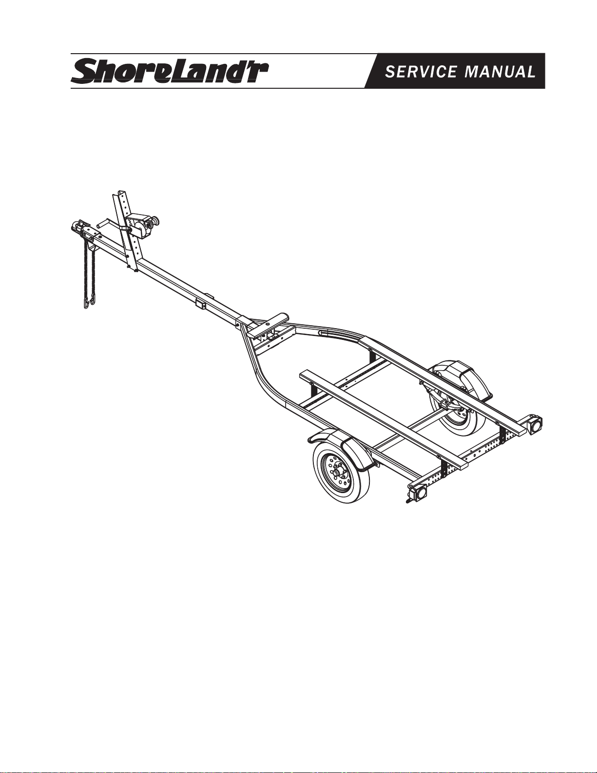
SLB10TS, SLB10TM & SLB10TL
Bundles Required
SLB10-TS
4300183 4.80 X 12-B Tire/MSilver Mod Rim
62340 Literature Bag - Trailers
65780-- Tongue 3X3X14 ga. X 7’
68343-- Frame Bundle, Fish Bunk
SLB10-TM
4300183 4.80 X 12-B Tire/MSilver Mod Rim
62340 Literature Bag - Trailers
65537-- Tongue 3X3X14 ga. X 8’ 6”
68343-- Frame Bundle, Fish Bunk
SLB10-TL
4300183 4.80 X 12-B Tire/MSilver Mod Rim
62340 Literature Bag - Trailers
65516-- Tongue 3X3X14 ga. X 10’
68343-- Frame Bundle, Fish Bunk
Midwest Industries, Inc. Ida Grove, IA 51445 800.859.3028 www.shorelandr.com M308185
TONGUE WEIGHT
The axle on this trailer is in a fixed position. The amount
of tongue weight that you have will depend on the
amount of gear and accessories that you have on your
boat. The location of the gear and accessories is
critical in determining the amount of tongue weight you
have. The recommended tongue weight for this trailer
is 7-10% of the total gross weight of the complete unit
including the trailer.
Page 1 of 8
Page 2
Wire Harness
Hole
Wire Harness
Hole
Midwest Industries, Inc. Ida Grove, IA 51445 800.859.3028 www.shorelandr.com M308185
Page 2 of 8
Page 3

Assembly Instructions
Locate the bundles and break all banding holding the items
to the frame. Break the hardware bag and sort all nuts and
bolts by size.
Assembling this trailer is easiest when it is assembled on
saw horses or stands.
Ton gue
This trailer is available with three different length tongues
depending on which model was ordered. Locate the tongue
supplied with your trailer. Place it on saw horses or a stand to
pre-assemble it before installing it into the trailer frame.
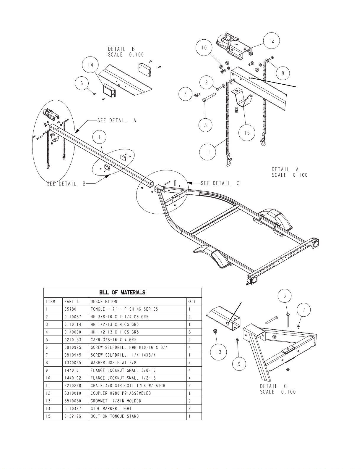
Side Marker Lights
The side marker lights for your trailer are shipped
unassembled to prevent damage during shipping. Locate
them. They are to be mounted to the sides of the tongue in
the holes that are provided, see Detail B. Insert the 66”
pigtail of the light into the center hole pushing it in the tongue
so the wire will go to the front of the tongue. Pull the end of
the wire out the hole provided in the top of the tongue. (See
Detail A.) Attach the light to the tongue using the two- No. 10
x 3/4” self-tapping screws provided. Tighten. Repeat this process of the second light on the other side of the tongue.
Tongue Wire Harness
Locate the tongue harness. Plug the wires from the two side
marker lights just installed into the two single brown wire
female plugs on the wire harness located approximately 48”
from the front plug of the tongue harness. Once the wires are
plugged together insert the rear plug on the tongue harness
into the same hole on the top of the tongue and push the wire
harness into the tongue. This will pull all of the wires back
down the hole and into the inside of the tongue. Pull on the
tongue harness rear plug until it comes out the rear of the
tongue. Once the wire harness is exposed out the rear of the
tongue, insert the rear plug through the hole provided in the
side of the tongue. See Detail C. Place the rubber grommets
supplied in the holes on each end of the tongue to protect the
wires during use.
Note that the wire harness supplied with the trailer is long
enough to fit the longest length tongue available for this frame.
The model you ordered will determine how much extra wire
length you will have in the tongue harness. All extra wiring
can be pushed back into the hole in the top of the tongue.
Coupler
See Detail A. Place the coupler on the end of the tongue.
Align holes and attach to the tongue using one 1/2” x 4” hex
bolt and flange lock nut in the rear hole of the coupler. Attach
the front of the coupler to the tongue using a 1/2” x 1 hex bolt
and flange lock nut on each side. Tighten.
Tongue Stand
See Detail A. Locate the tongue stand. Note that it has a dart
shape on one end. With the tongue stand positioned cross
ways with the tongue, insert the dart into the slotted hole in
the bottom of the tongue. Once inserted, rotate the tongue
stand so it is in line with the tongue. Line the hole in the other
end of the tongue stand with the hole provided in the bottom
of the tongue. Secure the tongue stand in place using a 1/2”
x 1 hex bolt and flange lock nut. Tighten.
Safety Chains
See Detail A. Place a 3/8” flat washer on to a 3/8” x 1-1/4”
hex bolt. Next place the bolt through the end link of one of
the safety chains. Insert the bolt through the hole provided in
the side of the tongue as shown. Place on another 3/8” flat
washer and secure with a 3/8” flange lock nut. Tighten.
Repeat this process on the other safety chain.
Installing the Tongue Assembly Into The Frame
Raise the back of the tongue up into the front tongue channel
of the frame. See Detail C. Slide it backwards until the rear of
the tongue is in the front cross member. Align the hole in the
end of the tongue with the hole provided in the front cross
member. Attach it to the frame by placing a 3/8” x 4” carriage
down through the front cross member and the hole provided
in the rear of the tongue. Secure with a 3/8” flange lock nut.
Place another 3/8” x 4” carriage bolt through the tongue channel and through the sides of the tongue. Secure with another
3/8” flange lock nut. Tighten.
The white ground wire of the tongue wire harness needs to
be attached to the frame to assure a positive ground and
proper light functioning. Place a No. 10 x 3/4” self-tapping
screw into the round ring attached to the white ground wire.
Thread the self- tapping screw into the hole provided on the
bottom leg of the front cross member. Tighten.
Midwest Industries, Inc. Ida Grove, IA 51445 800.859.3028 www.shorelandr.com M308185
Page 3 of 8
Page 4

Winch Post
The winch post comes fully assembled but will need to be
adjusted to fit your boat. See the final adjustment section for
instructions.
Slip the end of the winch post over the tongue as shown in
Detail D. Attach the winch post to the tongue using three3/8” x 4” hex bolts and flange lock nuts. Tighten only to hold
the winch post in position. It will be tightened later when
adjusting to fit the boat.
Remove the nut from the drive shaft of the winch. Align the
flat surfaces of the drive shaft with those in the winch handle
and slide into position. Replace the nut just removed from
the drive shaft. Tighten.
Midwest Industries, Inc. Ida Grove, IA 51445 800.859.3028 www.shorelandr.com M308185
Page 4 of 8
Page 5

Bunk Brackets and Bunks
Locate the bunk brackets. See Detail E and F. Note that the
front bunk brackets are located on the front of the cross
member while the rear bunk brackets are located on the rear
of the cross member. Choose a pair of holes for the bunk
location. Attach the bunk brackets to the cross members
using 3/8” x 1” carriage bolts, lock washers and hex nuts.
Hand tighten only because they will have to be adjusted
when the boat is placed on the trailer.
Position the bunks so that they are above the bunk brackets
just installed. Note that the mounting brackets attached to
the bunks are not centered on the bunks but are off center 4
inches. They can be installed either direction. Positioning them
so the extra bunk is to the rear will allow you to put a longer
boat on the trailer. This adjustment may also be critical when
trying to establish the correct tongue weight.
Attach the bunks to the brackets using 3/8” x 1” carriage bolts
and flange lock nuts. Tighten but do not over tighten because
the bunks must be allowed to rotate at this point so they will
conform to the boat when it is placed on the trailer.
Midwest Industries, Inc. Ida Grove, IA 51445 800.859.3028 www.shorelandr.com M308185
Page 5 of 8
Page 6

Springs
See Diagram. Place a spring bushing spacer
(Ref. No. 17) up inside the legs of the rear
spring loop of the spring bracket, then
insert a 9/16” x 3-1/4” hex fine threaded
spring bolt through the spring bracket and
the spring bushing spacer just installed.
Secure with a 9/16” hex fine threaded nut.
Locate a spring. Slip the flat end of the spring
inside the rear spring bracket loop above the
spring bushing spacer just installed. Attach
the front of the spring to the front spring loop
using another 9/16” x 3-1/4” hex fine
threaded spring bolt and hex fine threaded
nut. Tighten. Repeat this process on the
other spring.
Axle
Raise the axle up under the springs. Align
the pin on the bottom of the spring with the
hole provided in the spring mounting plate
welded to the top of the axle. Slide two- 3/8”
x 2-3/16” x 1-3/4” square U-bolts down over
the top of the spring. Align with the holes in
the spring mounting plate on the axle.
Secure the axle to the springs with 3/8” flange
lock nuts. Repeat this process on the other
spring. Tighten all nuts holding the axle to
the springs.
Tire And Wheel Assemblies
Mount the tire and wheel assemblies using
the 1/2” fine threaded tapered lug nuts
provided. Tighten to 80-90 ft/lb. of torque
using the rotation pattern as shown in the
ShoreLandr’s Owners Manual. Re-torque
the lug nuts after 50 miles of driving and then
periodically thereafter.
Midwest Industries, Inc. Ida Grove, IA 51445 800.859.3028 www.shorelandr.com M308185
Page 6 of 8
Page 7

Front Support Pad
Install the front support pad to the trailer tongue by placing
the legs of the pad support mounting bracket down over the
tongue. Secure in place by placing two- 3/8” x 4” carriage
bolts through the pad support mounting bracket, one on top
of the tongue and the other on the bottom. See Detail H.
Secure with 3/8” flange lock nuts. Do not tighten at this point
because they will be re-adjusted when the boat is placed on
the trailer.
Midwest Industries, Inc. Ida Grove, IA 51445 800.859.3028 www.shorelandr.com M308185
Page 7 of 8
Page 8

Trailer Adjustments
The adjustment of the trailer to your boat is very important
not only for the trailer, but also the boat. Failure to do so may
lead to potential failure or damage to either the trailer or boat.
Adjust as follows:
Pull the boat on the trailer. As you pull the boat on the trailer
check to make sure the bunks are high enough and close
enough to keep the keel of the boat from hitting the cross
members as it is loaded and unloaded. However, it is very
important that they are spaced as far apart as possible
because the farther they are spaced apart, the more stable
your boat will be on the trailer when towing. Allow the boat to
rest on the front support pad on the tongue and the bunks.
Bunk Adjustment
Once the boat clears the cross members the bunks must be
checked that they are properly spaced between the strakes
on the bottom of the boat. They must be located between the
strakes. If they aren’t, they can be adjusted either in or out by
moving the bunk brackets to a new set of holes provided in
the cross members. The bunks must be spaced equal
distances from the centerline of the trailer. When the proper
location is achieved, tighten the nuts and bolts holding the
bunk brackets to the frame.
Additional Adjustments
The bunks can also be adjusted for height in case additional
clearance is needed for either the cross members or
fenders.
Winch Post
Adjust the winch post backward to fit your boat. Note that the
rubber V-block has to be positioned directly above the boat
bow eye. This will give it maximum support and strength
forward in the event of a sudden stop. Attach the winch hook
and strap to the bow eye. Tighten. There will be a slight amount
of down pressure on the front of the boat when adjusted as
described. This is correct adjustment. The height of the rubber V-bow stop can be raised or lowered by removing the
two 3/8” x 1” hex bolts and flange lock nuts that attach it to
the upright winch post. Reposition and secure again using
the 3/8” x 1” hex bolts and flange lock nuts just removed.
When the winch post is in its proper location forward and
backward, tighten the three 3/8” x 4” hex bolts and flange
nuts securing the winch post to the tongue.
Tongue Weight
Position all of the gear that will be transported in the boat in
its normal location. Then check for proper tongue weight. The
tongue weight will vary depending on your total load but should
be in a range of 60 lb. minimum to 100 lb. maximum. TOO
LIGHT OF TONGUE WEIGHT WILL CAUSE YOUR UNIT
TO FISHTAIL WHEN BEING TOWED. If the tongue weight
of your unit does not fall within this range, you must
reposition the boat either forward or backward or else
relocate the gear inside the boat.
The bunks may have to be turned end for end to obtain the
proper tongue weight and still achieve optimum support for
your boat.
The bunks can be positioned so the extra bunk past the
mounting brackets is either forward or backward. This
adjustment can be used to either obtain proper tongue weight
or else give better support to longer boats.
Front Support Pad
The front support pad can be adjusted anywhere forward or
backward on the tongue to best fit and support your boat. It
can also be adjusted for height in the event you need it
adjusted higher to reach your boat keel. Once adjusted in the
proper location, tighten the mounting bolts and nuts.
Adjustments are now complete. Double check your boat for
fit. If desired fit has been achieved, tighten all fasteners that
may have either been left loose or have been loosened to do
the adjusting.
Re-check all fasteners on the complete trailer to make sure
they are all tight and ready for towing. All fasteners should be
periodically checked before towing.
The law requires that the white ground wire on both the tongue
wire harness and vehicle harness be properly grounded to
respective trailer and vehicle frames.
See your ShoreLand’r Owner’s Guide for further technical
information regarding your trailer and its components.
Midwest Industries, Inc. Ida Grove, IA 51445 800.859.3028 www.shorelandr.com M308185
Page 8 of 8
 Loading...