

Page 1
®
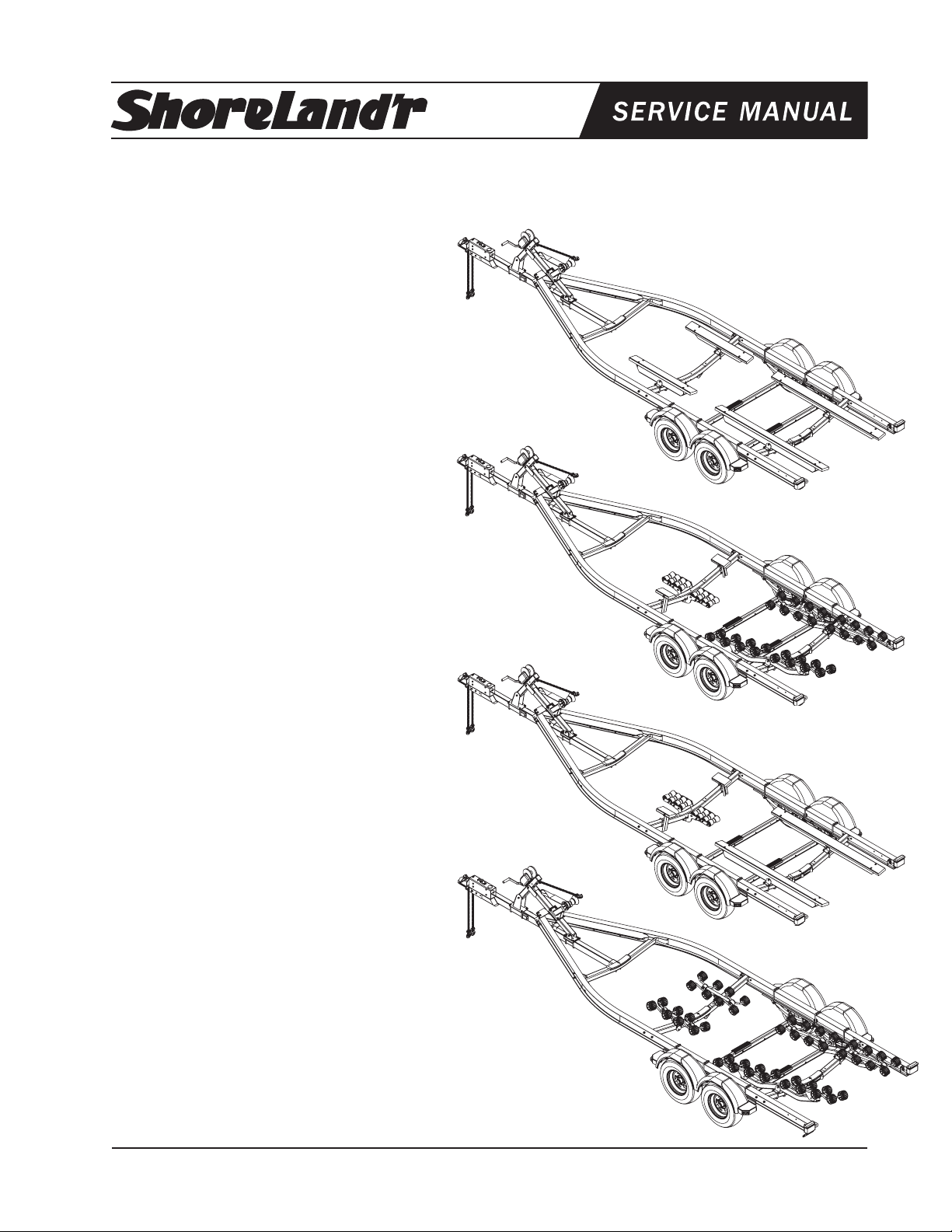
SLB60TAL, SLR60TAL, SLRB60TAL & SLXR60TAL
Aluminum Trailers
SLB60TAL
Bundles Required for SLB60TAL
69082 Literature Bag - Trailers - Brakes 1
6680600 Frame Bundle 6000 lbs. Aluminum Bunk 1
*ST215/75R 14C Tire / Galv. Dir Rim 4
4510354 Actuator 8000 lb. UFP - Plated 1
68732 Brake Box - Tandem 1
SLR60TAL
Bundles Required for SLR60TAL
69082 Literature Bag - Trailers - Brakes 1
6815700 Frame Bundle 6000 lbs. Aluminum Roller 1
*ST215/75R 14C Tire / Galv. Dir Rim 4
4510354 Actuator 8000 lb. UFP - Plated 1
68732 Brake Box - Tandem 1
SLRB60TAL
Bundles Required for SLRB60TAL
69082 Literature Bag - Trailers - Brakes 1
6709900 Frame Bundle 6000 lbs. Aluminum R/B 1
*ST215/75R 14C Tire / Galv. Dir Rim 4
4510354 Actuator 8000 lb. UFP - Plated 1
68732 Brake Box - Tandem 1
SLXR60TAL
Bundles Required for SLXR60TAL
69082 Literature Bag - Trailers - Brakes 1
8037700 Frame Bundle 6000 lbs. Aluminum XR 1
*ST215/75R 14C Tire / Galv. Dir Rim 4
4510354 Actuator 8000 lb. UFP - Plated 1
68732 Brake Box - Tandem 1
*Check with your dealer/customer service representative for current tire/rim assembly part number.
Midwest Industries, Inc. Ida Grove, IA 51445 800.859.3028 www.shorelandr.com 0003354
Page 1
REV C 4/28/06
Page 2
IMPORTANT: All hardware for your trailer is stainless
steel. It is important that you use an anti-seeze material
on the bolt threads when assembling to prevent gaulding.
Midwest Industries, Inc. Ida Grove, IA 51445 800.859.3028 www.shorelandr.com 0003354
Page 2
REV C 4/28/06
Page 3
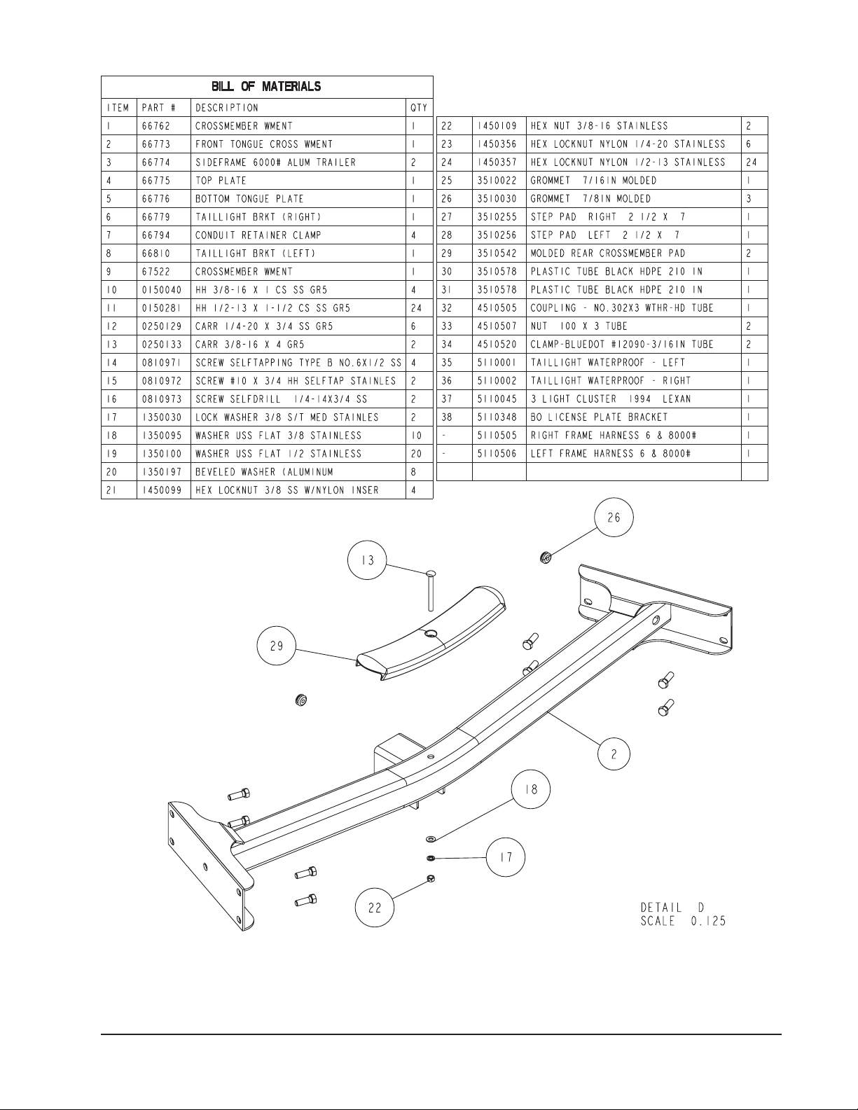
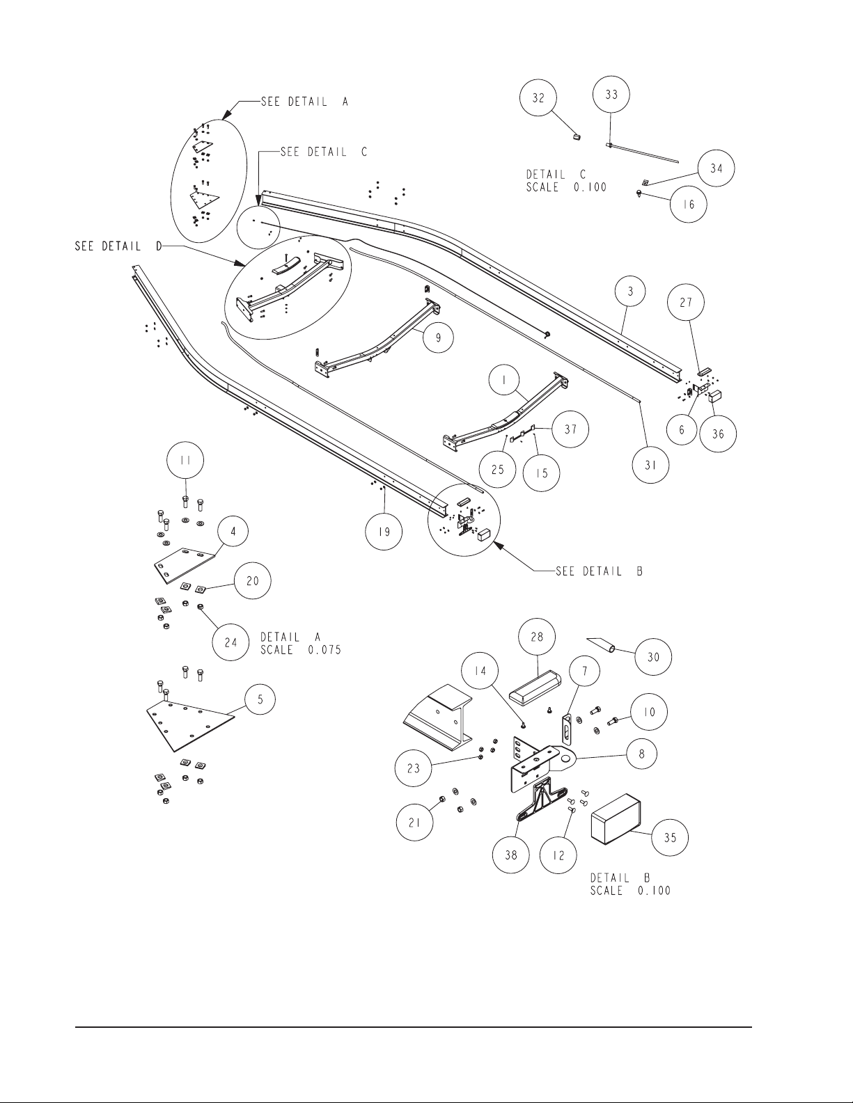
Diagram D
Midwest Industries, Inc. Ida Grove, IA 51445 800.859.3028 www.shorelandr.com 0003354
Page 3
REV C 4/28/06
Page 4
Midwest Industries, Inc. Ida Grove, IA 51445 800.859.3028 www.shorelandr.com 0003354
Page 4
REV C 4/28/06
Page 5
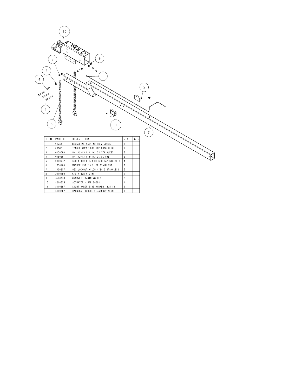
Diagram E
Attach the ground wire to the main frame by
driving the screw into the bottom flange of
the side frame. This will assure a positive
ground for the lighting.
Brake line:
Place one end of the tongue brake line into
the hole in the top of the tongue located just
behind the front joint of the two side frames.
Insert until the end of the line comes out the
front of the tongue. Place the actuator into
it’s approximate location on the tongue.
Remove the plastic plug in the rear of the
actuator and thread the brake line into
the port.Tighten. Place the actuator in it’s
proper location by aligning the holes in
the mounting channel with the holes in
the tongue.
Tongue:
Fasten the tongue in the rear at the front cross member location with a 1/2”
X 4-1/2” stainless steel hex bolt and 1/2” stainless steel flat washers under
the bolt head and the 1/2” stainless steel lock nut with nylon insert. Move
the tongue up to the lower frame plate of the frame. Line up the holes,
fasten the tongue in the frame with two (2) 1/2” X 3-9/16” X 5” stainless
steel square u-bolts, 1/2” beveled aluminum washers, 1/2” stainless steel
washers and 1/2” stainless steel hex lock nut with nylon inserts at the front
of the tongue plates; Refer to Detail E and F. Connect the tongue brakeline to the sideframe with a brakeline coupling (Ref.#30 on page 4).
Safety Chain:
Mount the safety chains to the front on the tongue using a 1/2” X 1-1/2” stainless steel hex bolt (Ref#4) with a 1/2” stainless steel flat washer at the head of
the bolt, followed by a safety chain through the drop tongue tube and secure
with a 1/2” stainless steel hex locknut with nylon insert. Repeat on other side.
Refer to Diagram E.
Wiring:
Plug in the tongue wire harness to the side frame wire harnesses located on
the first crossmember. Pull the wire out the hole in the tongue with either the
brown and yellow or brown and green plug.
Actuator:
Mount the actuator (Item #10) to the drop
tongue section using three (3) 1/2” X 4-1/2”
stainless steel hex bolts (Item #3) and 1/2”
stainless steel hex lock nuts with nylon
inserts.
Place a grommet around the brakeline
where it comes out of the top of the tongue
to keep it from vibrating and chaffing as it is
being towed. Form the remaining end of the
brake line so it will mate up with the brake
line running down the side frame. Secure the
two lines together with the brass coupling
provided in Hardware box 66801. Tighten
securely to prevent leaks but do not over
tighten causing the threads in the fitting to
strip.
White Ground Wire Installation:
The white ground wire must be grounded to the trailer frame with a 1/4” X
3/4” stainless steel self grounding tap screw.
Midwest Industries, Inc. Ida Grove, IA 51445 800.859.3028 www.shorelandr.com 0003354
Page 5
REV C 4/28/06
Page 6
6675200
Winch Assembly for 6, 7, 8300 lb. Aluminum Trailers
Diagram P
Mount the winch post assembly to the tongue at a
location that best fits your watercraft. Secure the
winch post base weldment (Item #3) to the tongue using two (2) 1/2” X 3-9/16” X 5” stainless steel square
u-bolts (Item #13) and four (4) 1/2” stainless steel
hex lock nuts with nylon inserts. Mount the winch
post angle tube weldment (Item #4) on the tongue
at a height that would best fit your watercraft using a
1/2” X 3-9/16” X 5” stainless steel square u-bolt over
the flange as shown in the drawing. Place the legs of
the U-bolt into the winch hold down clamp (Item #7)
and secure with two (2) 1/2” stainless steel hex lock
nuts with nylon inserts.
Midwest Industries, Inc. Ida Grove, IA 51445 800.859.3028 www.shorelandr.com 0003354
Page 6
REV C 4/28/06
Page 7

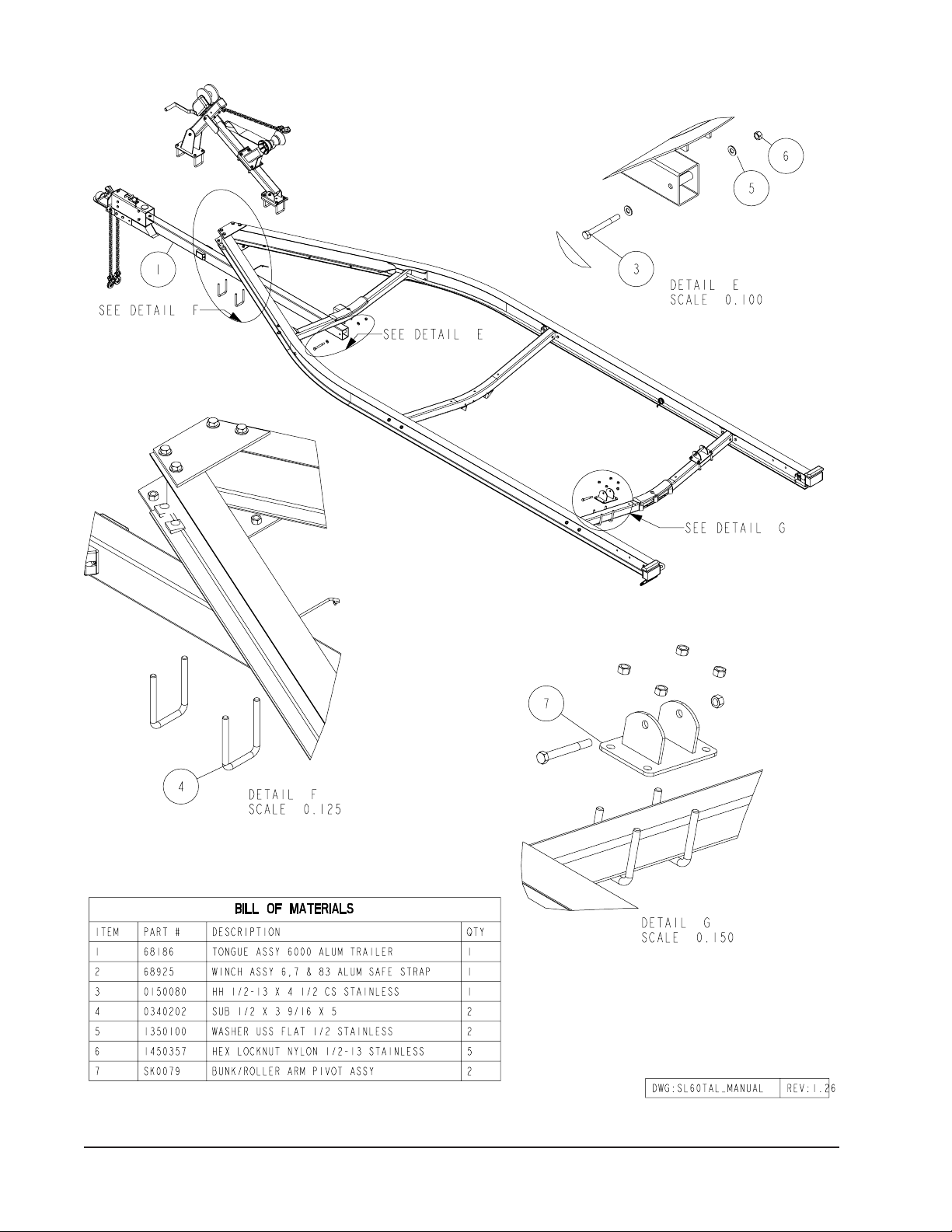
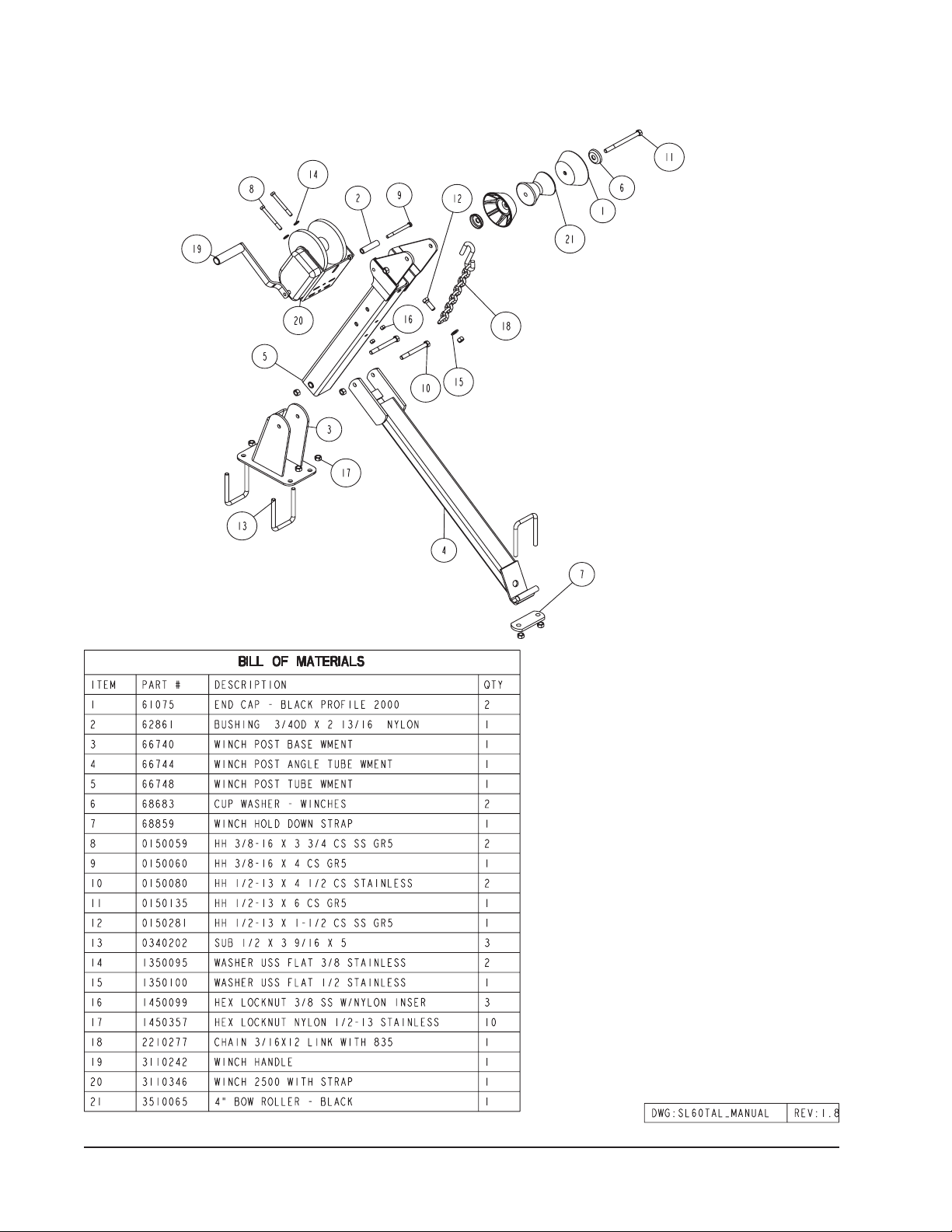
6892500
Winch Assembly for 6, 7, 8300 lb. Aluminum Trailers with Safety Strap
Mount the winch post assembly to the tongue at a location
that best fits your watercraft. Secure the winch post base
weldment (Item #3) to the tongue using two (2) 1/2” X 3-9/16”
X 5” stainless steel square u-bolts (Item #13) and four (4) 1/2”
stainless steel hex lock nuts with nylon inserts. Mount the
winch post angle tube weldment (Item #4) on the tongue at
a height that would best fit your watercraft using two (2)1/2”
X 3-9/16” X 5” stainless steel square u-bolt over the flange
as shown in the drawing. Place the legs of the U-bolt into the
winch hold down clamp (Item #7) and secure with four (4)
1/2” stainless steel hex lock nuts with nylon inserts.
Midwest Industries, Inc. Ida Grove, IA 51445 800.859.3028 www.shorelandr.com 0003354
Page 7
REV C 4/28/06
Page 8

Final Assembly Instructions
Remove and sort the small parts from
the frame.
Reference Standing at the rear of
the trailer will determine the right and
left sides of the trailer for assembly
instructions.
Rocker Bogie:
Ref e r to Detail H, Page 6. No t e
there is a grease zerk in the center
bushing of the rocker bogie. Position the rocker bogie into the center
mounting channel of the spring
bracket so that the grease zerk is
pointing down. This is necessary
so that it can be serviced in the field
when needed. Align the center hole of
the rocker (6239210) with the center
hole of the spring bracket. Insert and secure with a 3/4” X 4-1/2” stainless steel
hex bolt from the outside in and tighten
with a 3/4” stainless steel hex lock nut.
Axles:
Note: The hook end of the springs
must point to the rear of the trailer, on
both axles!
Position the axles so they are properly aligned with the trailer. Position
the brake axle so that the disc brake
calipers are on the back side of the
axle. Place the springs on the topside
of the spring pads welded to the axle.
(See chassis diagram). Place a spring
clamp on the top center of the spring.
Place the 1/2” x 6-1/2” stainless steel
square U-bolts down over the top of
the spring clamp, spring and axle.
Place the spring and axle U-bolt plate
onto the ends of the two U-bolts.
Secure in pla ce with 1/2” st ain les
steel lock nuts. Thread onto the Ubolts but do not tighten securely until
the complete unit is in position on the
trailer. Repeat on the other spring.
Place on e of the sp r i n g bracket
bushings into the rear of the spring
bracket an d secure with a 9/16” x
3 1/4” stainless steel hex bolt and
9/16” stainless steel hex lock nut. Repeat in other spring bracket.
Position the rear axle under the frame,
hook the hook loop of the spring around
the bushings just installed. Note that
if the axle is positioned too low when
trying to hook, the hooks will not hook
around the bushings.
Raise the front of the springs up so they
align with the rear hole in the axle rocker
bogie just installed. Secure in place with
9/16” x 3-1/4” stainless steel hex bolts
and 9/16” stainless steel lock nuts.
Install another spring bracket bushing in the front hole on the rock arm
assembly. Secure with a 9/16” x 3-1/4”
hex bolt and lock nut. Tighten.
Hook the hook end of the spr ings
mounted to the front axle over the
bushing just installed in the rocker arm
assembly. Then swing the front of the
spring up and attach the front mounting
hole in the spring bracket with another
9/16” x 3-1/4” hex bolt and lock nut. Tighten all axle U-bolts and spring bolts.
Brake Line Installation:
Open hardware box No. 66801 and
sort. Locate the long (88’) brake line
and straighten.
Remove one of the brass plugs from
the port in the brass block on the left
brake caliper that best aligns with the
routing of the line. Note also that the bolt
holding the brass block to the caliper can
be loosened so that the brass block can
be rotated to better accommodate the
angle that the brake line approaches the
block on the caliper. Thread the brake
line fitting into this port to hold the line in
position making sure that the line does
not rub or touch the spring. Re-tighten
the bolt in the brass block if it has been
loosened to rotate the block.
Locate the five (5) line clamps and the
1/4” self tapping screws. Route the
line down the back side of the axle
and secure to the axle with the five
(5) clamps and self tapping screws.
Note that the axle is pre-drilled for the
mounting screws.
Route the brake line over to the brass
block on the right brake caliper. Remove
both plugs on the right caliper block.
Thread the other end of the brake line
into one of the ports on the brass block.
Thread the 18” brake hose male end
into the other port from which the plug
was removed and tighten. Position the
brass block so that neither the hose
nor the brake line will contact or rub
the spring. Tighten all fittings.
Place the other end of the hose up
through the hole provided in the brake
li ne cli p bra cket . Secu re in place
wi t h the ho se clip provid ed. Ite m
No. 27 in Diagram F, Page 6.
Repeat this process on the second
axle using the component parts in
hardware box 66928.
Locate the brass tee in box 66928.
Thread the male port of the tee into the
female end of the brake hose of the
front axle. Tighten. Remove the plastic
cap from the end of the frame brake line
coming out of the black plastic tube in
the side frame by the axle. Uncoil the
brake line enough so that it will reach
the port of the tee just threaded into the
brake hose. Thread the brake line fitting
into the top port of the tee and tighten.
Locate the 40” long brake line tube
in box 66928. Thread one end of the
line into the remaining port of the tee
installed in the previous step. Route
the line back to the second axle. Place
a coil in the line to use up the excess
line and then connect the other end of
the line into the hose coming from the
second axle. Tighten both fittings. Note
that the coil in the line will absorb the
vibration created during towing.
Bleeding the Brake System
Bleed the brake system as specified
in the brake manual. The bleeding
process is necessary to remove ALL air
entrapped in the system in order for the
brake system to function properly.
Tire And Wheel Assemblies
Mount the tire and wheel assemblies
using the 1/2” fine threaded tapered
lug nuts provided. Tighten to 80-90
ft/lb. of torque using the rotation pattern as shown in the Sho reLandr ’s
Owners Manual. Re-torque the lug
nuts after 50 miles of driving and then
periodically thereafter.
Brakes:
Refer to the Brake Service Manual for
service and maintenance.
Midwest Industries, Inc. Ida Grove, IA 51445 800.859.3028 www.shorelandr.com 0003354
Page 8
REV C 4/28/06
Page 9

Axle Assembly
Midwest Industries, Inc. Ida Grove, IA 51445 800.859.3028 www.shorelandr.com 0003354
Page 9
REV C 4/28/06
Page 10

Chassis Assembly
Tire Size & Carrying Capacity Chart
Tire Size: ST215/75R-14
Load Range: C
Carrying Capacity: 6000 lbs.
Diagram F
Midwest Industries, Inc. Ida Grove, IA 51445 800.859.3028 www.shorelandr.com 0003354
Page 10
REV C 4/28/06
Page 11

Midwest Industries, Inc. Ida Grove, IA 51445 800.859.3028 www.shorelandr.com 0003354
Page 11
REV C 4/28/06
Page 12

Diagram I
Diagram J
Diagram K
Midwest Industries, Inc. Ida Grove, IA 51445 800.859.3028 www.shorelandr.com 0003354
Page 12
REV C 4/28/06
Page 13

Detail L
Rear Bunk Assembly
Mount the rear bunk support weldments to the pivot
weldments by placing them in the channel of the pivot
weldments and attaching with 1/2” X 4-1/2” stainless
steel hex bolts and 1/2” stainless steel lock nuts. See
Detail L. Place the bunk assembly over the support
weldment, align the holes of the bunk brackets with
the holes in the support weldment and secure using
1/2” X 1-1/2” stainless steel hex bolts and 1/2” stainless stee lock nuts. Tighten but do not over tighten
because the bunk must rotate to conform to the boat
bottom.
Midwest Industries, Inc. Ida Grove, IA 51445 800.859.3028 www.shorelandr.com 0003354
Page 13
REV C 4/28/06
Page 14

Detail M
Front Bunk Assembly
Mount the front bunk support weldments to the pivot weldments by placing them in the channel of the pivot
weldments and attaching with 1/2” X 4-1/2” stainless steel hex bolts and 1/2” stainless steel lock nuts. See Detail M. Place the bunk assembly over the support weldment, align the holes of the bunk brackets with the holes
in the support weldment and secure using 1/2” X 1-1/2” stainless steel hex bolts and 1/2” stainless steel lock
nuts. Tighten but do not over tighten because the bunks must rotate to conform to the boat bottom.
Midwest Industries, Inc. Ida Grove, IA 51445 800.859.3028 www.shorelandr.com 0003354
Page 14
REV C 4/28/06
Page 15

Diagram N
Midwest Industries, Inc. Ida Grove, IA 51445 800.859.3028 www.shorelandr.com 0003354
Page 15
REV C 4/28/06
Page 16

Midwest Industries, Inc. Ida Grove, IA 51445 800.859.3028 www.shorelandr.com 0003354
Page 16
REV C 4/28/06
Page 17

Detail O
Rear Roller Arm Assemblies:
Mount the rear roller arm assemblies to the pivot weldments by placing them in the channel of the pivot weldments and
attaching with 1/2” x 4-1/2” stainless steel hex bolts and 1/2” stainless steel lock nuts. See Detail O.
Midwest Industries, Inc. Ida Grove, IA 51445 800.859.3028 www.shorelandr.com 0003354
Page 17
REV C 4/28/06
Page 18

Diagram P
Midwest Industries, Inc. Ida Grove, IA 51445 800.859.3028 www.shorelandr.com 0003354
Page 18
REV C 4/28/06
Page 19

Midwest Industries, Inc. Ida Grove, IA 51445 800.859.3028 www.shorelandr.com 0003354
Page 19
REV C 4/28/06
Page 20

TRAILER ADJUSTMENTS:
The adjustment of the trailer to your boat is very important
not only for the trailer, but also the boat. Failure to do so may
lead to potential failure or damage to either the trailer or boat.
Rear Support System
Place the boat on the trailer so that the transom is located
at the rear of the support system. On an RB bunk trailer,
the transom of the boat should be within 1-2” of the end of
the bunk. The center of the rear rollers on the roller rack
should be approximately 4” from the transom. This gives you
maximum support on the transom.
The rear cross member is adjustable forward or backward to
allow the trailer to be adjusted to various length boats. This
is accomplished by removing the two bolts that attach the
ends of the rear cross member to each side frame. Slide the
assembly to another set of holes provided in the side frames
that is more desirable, and then re-attach the cross member
in the new location with the bolts just removed.
The wire harness for the three-light identification light must
be re-positioned where it comes from the black wire harness
tubing to eliminate slack and sagging of the wiring.
Bunks
The bunks must be positioned far enough apart to give
your boat as much stability as possible while transporting.
Position the bunks so they are located just to the outside
of a strake that your boat may have. This will help center
your boat and assist when loading. The bunks need to be
adjusted up high enough to keep the keel from resting on the
center pads. A minimum of one to two inches of clearance is
desirable.
RB Bunk trailers would be adjusted the same way.
Rollers
Position the roller racks so they are far enough apart
to give your boat stability while transporting. When the
desired width is achieved, move the roller rack system
so that the rollers are just to the outside of a strake. The
rollers need to be adjusted so that you have a minimum
of one to two inches of clearance between the keel of
the boat and the center cross member pads. This will
help center the boat when loading and unloading.
When the desired position is determined, tighten only enough
to hold the bunks or rollers from moving while the other
a d ju s t m e n ts a r e be i ng m a de . Fi n a l ti g h t en i n g
will be done at the end of the adjusting process.
Front Support System
Bunk
The front bunks should be adjusted either in or out so that
the bunk will run just to the outside of the strake of the boat.
The bunks can be adjusted either farther in or out from the
location of the rear bunk position. Adjust the bunks up so
that there is approximately 1” clearance between the keel
of the boat and the center cross member pad.
RB and Roller
The ke el of the boat must rest on the cen ter of the
front keel roller system creating a three-point support
system. The keel roller system is designed to fit most
boats without needing any further adjustment.
Once the boat is resting on the roller cradle assembly, the
stabilizer pads can be adjusted. Slide the pad up against
the boat bottom by hand. It is not necessary that they carry
much weight. They are designed to give your boat added
stability while being towed. It may be necessary to adjust the
assembly up so that they can be moved further apart giving additional support. Pull the assembly away from the
boat. Place the U-bolt that holds the assembly to the cross
member in a lower hole in the bracket. Then push the
assembly back agai nst the boat. Tighten in position.
Winch Post:
Slide the winch post base backward on the tongue until the
bow roller comes in contact with the boat. This bow roller
needs to be positioned directly above the boat bow eye to
prevent your boat from moving forward in the event of a
sudden stop. It can be moved up or down by sliding the
winch post angle tube either forward or backward on
the tongue, thus raising or lowering the bow eye roller. Attach the winch strap and crank winch tight.
It may also be used to keep your boat on the trailer while
loading and unloading at the ramp, especially with a roller
trailer.
Tighten all bolts and U-bolts at this time in the winch post
assembly not previously tightened.
Attach the bow eye safety chain into the bow eye of the
boat as well. This is just another added level of protection to
keep your boat and trailer together as one unit.
Axle Adjustment:
The amount of tongue weight on you trailer can be adjusted as follows:To lower the tongue weight, adjust the axle
assembly forward. To increase the tongue weight, adjust
the axle assembly backward. The distance that the axle
assembly has to be moved will vary because it is directly
related to the weight and center of gravity on the boat placed
on it. Best towing is achieved when the tongue weight is
5-7% of the total gross load of the complete unit.
NOTE: Brake line and wire harness will need care when
moving the assembly.
NOTE: Check all fasteners, they must be tightened
before towing.
Cautions / Warnings
The law requires that the white ground wire on both
the tongue wire harness and the vehicle harness be
properly grounded to the respective trailer and vehicle
frames.
Midwest Industries, Inc. Ida Grove, IA 51445 800.859.3028 www.shorelandr.com 0003354
Page 20
REV C 4/28/06
 Loading...