

Page 1
®
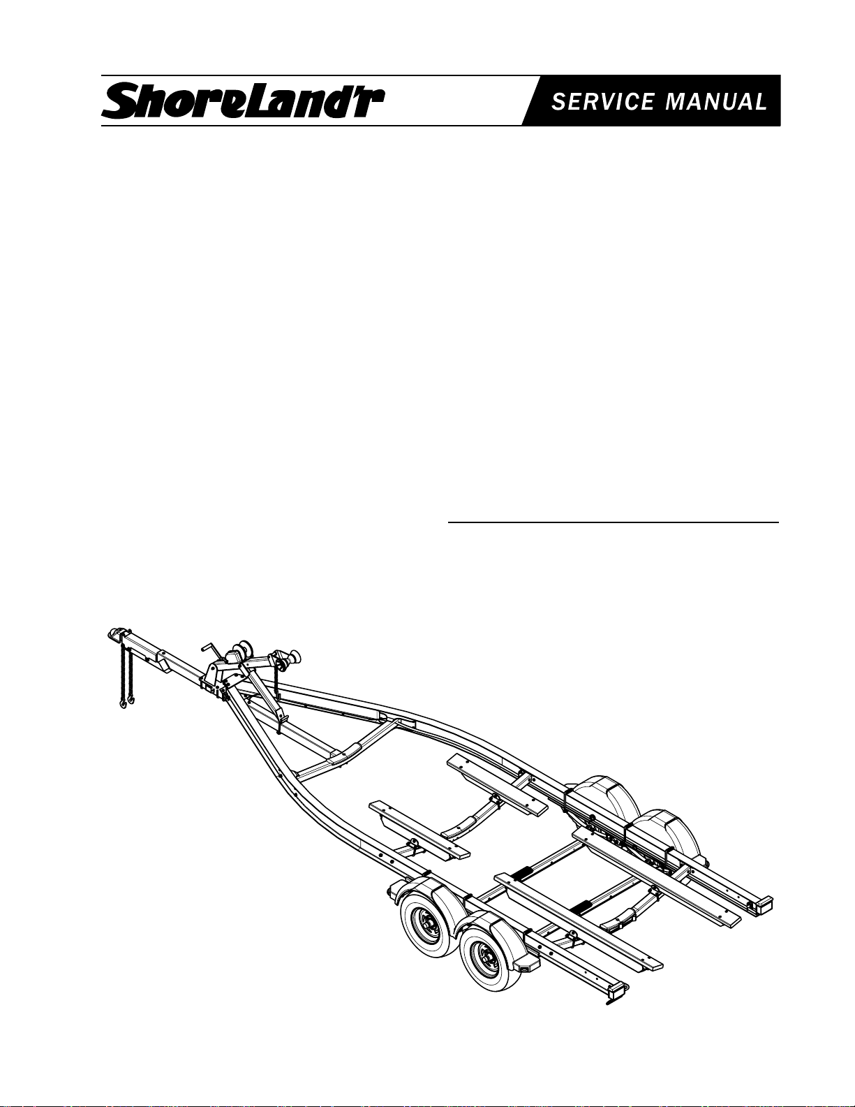
SL60T
Aluminum Bunk Trailer
Bundles Required
6680600 Frame Bundle 6000# Aluminum 1
4300198 ST215/75R 14C Tire / Galv. Dir Rim 2
4510499 Actuator 7500 lb. Tandem - Disc 1
Tire Size & Carrying Capacity Chart
Tire Load Carrying
Size Range Capacity
ST215/75R-14 C 1870 lbs. per tire
Refer to the tire side wall for proper tire pressure.
Cautions / Warnings
The law requires that the white ground wire on both the
tongue wire harness and the vehicle harness be
properly grounded to the respective trailer and vehicle
frames.
Double check all nuts and bolts --- tighten before
towing.
Tongue Weight Adjustments
Approximate Tongue Weight for Best Towing. Tongue
weight too high, move the axle assembly forward. Tongue
weight too low, move the axle assembly backward. Tongue
weight should be 5% to 7% of the total gross weight of the
boat and trailer combined.
Final Assembly Instructions
Remove the small parts from the frame by cutting the
bands. Remove the bolt bag and sort all nuts and bolts by
size.
Refer to the following individual pages for assembly
instructions.
Reference: Standing at the rear of the trailer will determine the right and left sides of the trailer for assembly
instructions.
NOTE: ShoreLand’r offers their product line in either
galvanized or painted finish. When ordering parts it is
important that you specify the finish or color you have on
your product. The five (5) digit number along with the two
(2) digit space _ _, notes the parts which can be purchased
with various finishes. When ordering these items use the
five (5) digit prefix and include the following two (2) digit
suffix for the proper finish.
Finish/Color Suffix
00 or G Galvanized
Decals:
4810501 DECAL LARGE SHORELAND’R........... 2
4811334 DECAL GREASE ZERK ARROW ......... 2
4850360 DECAL NMMA CERTIFIED TRAILER... 1
4810709 DECAL TRAILER CAUTION/WARN ..... 1
Made in the USA Midwest Industries, Inc. Ida Grove, IA 51445 800.859.3028 0002998
Page 1 www.shorelandr.com REV 02/08/01
Page 2

Made in the USA Midwest Industries, Inc. Ida Grove, IA 51445 800.859.3028 0002998
Page 2 www.shorelandr.com REV 02/08/01
Page 3

Frame:
Trailer Adjustments:
The SL60T frame is assembled by the manufacturer.
Please review all assembly parts drawings throughout this
service manual. This parts breakdown is reference to
various components that make up this trailer.
Tongue:
Slip the tongue into the front frame cap of the frame. Line
up the holes, fasten the tongue in the frame with two (2) 1/
2” X 3-9/16” X 5” square u-bolts, 1/2” beveled aluminum
washers, 1/2” stainless steel washers and 1/2” hex lock nut
with nylon inserts at the front of the tongue plates; fasten
the tongue in the rear with a 1/2” X 4-1/2” hex bolt and 1/2”
flat washer under the nut and bolt. Connect the tongue
brakline to the sideframe with a brakeline coupling
(Ref.#29).
Wiring:
Plug in the tongue wire harness to the side frame wire
harnesses located on the first crossmember. The white
ground wire must be grounded to the trailer frame with a
3/4” self grounding tap screw.
Place the boat onto the trailer so that is resting on the
bunks. This trailer is more flexible in its adjustment from
front to back but the boat should be positioned so that the
transom is being supported by the bunk. Once the boat is
positioned as above make the following adjustments.
Bunk:
Position the bunks in the back of the trailer so that they are
located between the keels or strakes and so that they won’t
interfere when loading and unloading. Once positioned,
tighten the u-bolts in the mounting brackets.
Position the front bunks in the desired area and adjust for
proper pressure of the bunks to the boat hull. CAUTION:
Do not over adjust the front bunks - the conform to they
must boat’s hull.
Winch Post:
Once the boat is positioned on the trailer, adjust the winch
post to the boat. Loosen the u-bolts and move the winch
assembly so that the top rubber bow roller is just above the
bow eye. Tighten.
NOTE: Double-check all fasteners - they must be
tightened before towing.
Made in the USA Midwest Industries, Inc. Ida Grove, IA 51445 800.859.3028 0002998
Page 3 www.shorelandr.com REV 02/08/01
Page 4
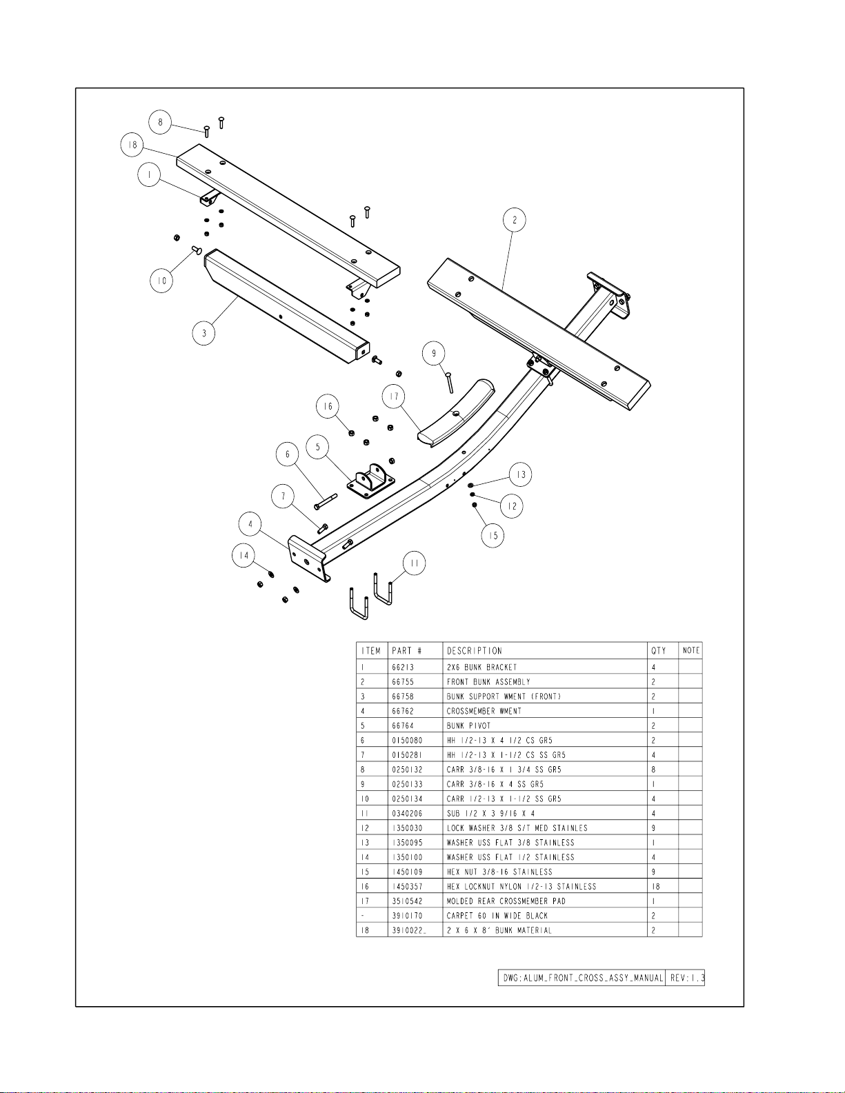
Front Bunk Assembly:
Mount the bunk assembly (Ref#2) onto the
bunk support weldment using two (2) 1/2”
X 1-1/2” carriage bolts (Ref#10) and secure
with two (2) 1/2” hex lock nuts with nylon
inserts. Mount the bunk support weldment
(Ref#3) into the bunk pivot base weldment
(Ref#5) using a 1/2” X 4-1/2” hex head bolt
(Ref#6) and secure with a 1/2” hex lock nut
with nylon insert (Ref#16). Repeat this procedure on the opposite side of the trailer.
Note: The bunk pivot base weldment is adjustable on the front cross. Loosen the 1/2”
u-bolts enough to move the bunk pivot base
weldment in or out on the front cross to a
location that best conforms to your watercraft.
Made in the USA Midwest Industries, Inc. Ida Grove, IA 51445 800.859.3028 0002998
Page 4 www.shorelandr.com REV 02/08/01
Page 5

Rear Bunk Assembly:
Mount the bunk assembly (Ref#2) onto the
bunk support weldment using two (2) 1/2”
X 1-1/2” carriage bolts (Ref#10) and secure
with two (2) 1/2” hex lock nuts with nylon
inserts. Mount the bunk support weldment
(Ref#3) into the bunk pivot base weldment
(Ref#5) using a 1/2” X 4-1/2” hex head bolt
(Ref#6) and secure with a 1/2” hex lock nut
with nylon insert (Ref#16). Repeat this procedure on the opposite side of the trailer.
Note: The bunk pivot base weldment is adjustable on the front cross. Loosen the 1/2”
u-bolts enough to move the bunk pivot base
weldment in or out on the front cross to a
location that best conforms to your watercraft.
Made in the USA Midwest Industries, Inc. Ida Grove, IA 51445 800.859.3028 0002998
Page 5 www.shorelandr.com REV 02/08/01
Page 6

Brakeline:
Run the brakeline through the end of the
tongue and up through the second wire hole
on top of the tongue as shown in drawing.
Insert grommet.
Cylinoid:
Locate the cylinoid in the brakeline kit for
first axle (66801). Insert the cylinoid into the
rear of the actuator. Connect the brakeline
from the tongue to the cylinoid.
Actuator:
Mount the actuator (Ref#10) on the drop
the tongue using two (2) 1/2” X 4-1/2” hex
bolts (Ref#3) and 1/2” stainless steel hex
lock nuts with nylon inserts (Ref#7).
Safety Chain:
Mount the safety chains to the front on the
tongue using a 1/2” X 5-1/2” hex bolt
(Ref#4) with a 1/2” stainless steel flat
washer at the head of the bolt, followed by
a safety chain through the drop tongue tube.
Place the other safety chain on the bolt on
the opposite side of tongue and secure with
a 1/2” stainless steel flat washer and 1/2”
stainless steel hex lock nut with nylon insert.
Made in the USA Midwest Industries, Inc. Ida Grove, IA 51445 800.859.3028 0002998
Page 6 www.shorelandr.com REV 02/08/01
Page 7

Winch Post:
Mount the winch post assembly to the
tongue at a location that best fits your watercraft. Secure the winch post base
weldment (Ref#2) to the tongue using two
(2) 1/2” X 3-9/16” X 5” square u-bolts
(Ref#11) and four (4) 1/2” stainless steel
hex lock nuts with nylon inserts. Mount
the winch post angle tube weldment
(Ref#3) on the tongue tube at a height
that would best fit your watercraft using a
1/2” X 3-9/16” X 5” square u-bolt over the
flange as shown in the drawing. Place the
legs of the u-bolt into the clamp (Ref#21)
and secure with two (2) 1/2” stainless
steel hex lock nuts with nylon inserts.
Made in the USA Midwest Industries, Inc. Ida Grove, IA 51445 800.859.3028 0002998
Page 7 www.shorelandr.com REV 02/08/01
Page 8
Made in the USA Midwest Industries, Inc. Ida Grove, IA 51445 800.859.3028 0002998
Page 8 www.shorelandr.com REV 02/08/01
Page 9

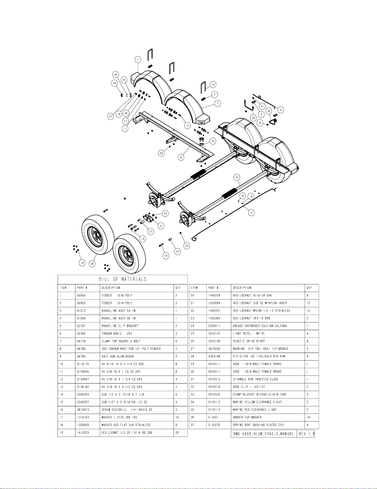
Rocker Bogie:
Align the center hole of the rocker (6239210) with the center
hole of the spring bracket. Insert and secure with a 3/4” X 41/2” hex bolt from the outside in and tighten with a 3/4” hex
lock nut.
Axles:
Note: Make certain the hook end of the springs point in the
same direction to the rear of the trailer, on both axles! For the
rear spring and axle - place a S-3207G, galvanized spring
bracket bushing, in the rear of the spring bracket. Insert the
9/16” X 3-1/4” hex bolt through the bracket from the outside
in and tighten with a 9/16” hex lock nut. Slide the end of the
hook spring over the bushing; raise the front of the spring
and fasten with a 9/16” X 3-1/4” hex bolt and 9/16” hex lock
nut. Repeat on the opposite side of the axle.
For installation of the front spring and axle repeat the previous procedure, however, place the bushing in the rocker box
in the hook end of the spring. Insert the bolts and secure with
9/16” lock nuts as before.
Mount the tire and rim assemblies using 80-90 lbs. of torque
on the lug nuts using a proper tightening apparatus or tool.
Brakes:
Refer to the Brake Service Manual for service and maintenance.
Made in the USA Midwest Industries, Inc. Ida Grove, IA 51445 800.859.3028 0002998
Page 9 www.shorelandr.com REV 02/08/01
 Loading...