

Page 1
®
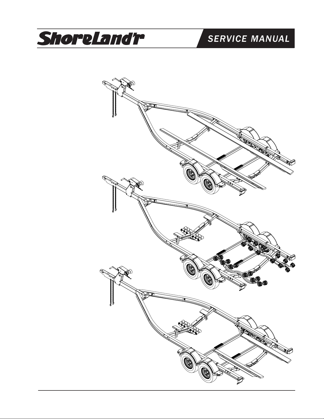
SLB46TBAL, SLR46TBAL & SLRB46TBAL
Aluminum Trailers
SLB46TBAL
Bundles Required for SLB46TBAL
69082 Literature Bag - Trailers - Brakes 1
6730200 Frame Bundle, SLB46TBAL 1
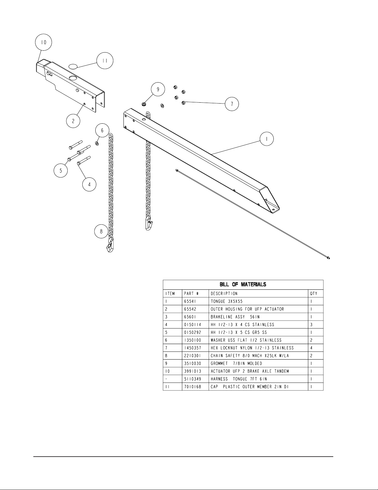
6704600 55” Tongue Assy w/2 Brakes 1
*ST185/80R 13C Tire / Galv. Dir Rim 4
*Check with your dealer/customer service representative for current tire/rim assembly
part number.
SLR46TBAL
Bundles Required for SLR46TBAL
69082 Literature Bag - Trailers - Brakes 1
6815800 Frame Bundle, SLR46TBAL 1
6704600 55” Tongue Assy w/2 Brakes 1
*ST185/80R 13C Tire / Galv. Dir Rim 4
*Check with your dealer/customer service representative for current tire/rim assembly
part number.
SLRB46TBAL
Bundles Required for SLRB46TBAL
69082 Literature Bag - Trailers - Brakes 1
6736000 Frame Bundle, SLRB46TBAL 1
6704600 55” Tongue Assy w/2 Brakes 1
*ST185/80R 13C Tire / Galv. Dir Rim 4
*Check with your dealer/customer service representative for current tire/rim assembly
part number.
Midwest Industries, Inc. Ida Grove, IA 51445 800.859.3028 www.shorelandr.com 0003629
Page 1 3/09/06
Page 2
FINAL ASSEMBLY INSTRUCTIONS
Remove the hardware bag from the frame, remove parts and sort by size.
IMPORTANT: All hardware is stainless steel.
Use an anti-seize material on bolt threads when
assembling to prevent gaulding.
TONGUE
The tongue comes shipped positioned backwards
in the frame.
Remove the nut and bolt that holds the tongue in
place and discard. Remove the tongue from its
ship position and install correctly in the front tongue
channel.
Line the holes in the tongue with the holes in the
tongue channel. Install the 1/2” x 4” hex bolt in the
front cross hole and secure with a 1/2” lock nut.
Re move th e wire harne s s from the rea r of
the t o n gue. P l a c e th e w i re h a r n e ss an d
the brake line thr oug h the hol e provided in
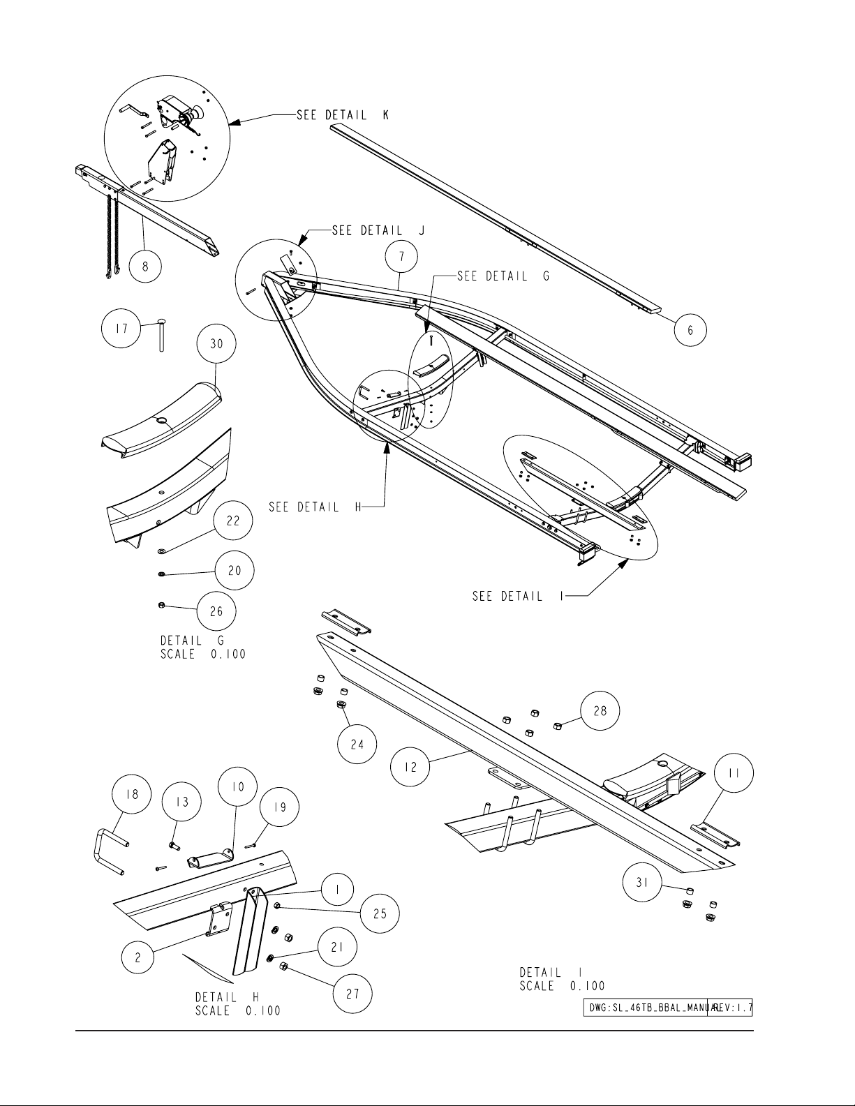
the tongue cover plate. (See Detail J).
Se c u r e t h e t o n gue c ove r pl a t e w i t h t h e
same 1/2” x 1-1/2” hex bolt that secures the
Midwest Industries, Inc. Ida Grove, IA 51445 800.859.3028 www.shorelandr.com 0003629
Page 2 3/09/06
back on the tongue to the tongu e ch annel of the frame. Secure with a 1/2” lock nut. Tighten both bolts just installed.
Plug the tongue wire harness ends into the frame harnesses by matching colors and ends. Push the extra wire either into the rear of the tongue
or remove the grommets in the side frame and place the extra wire in
the side frame. Replace grommets.
Page 3

White Ground Wire Installation
Pl a c e the self-t a pping scr e w pr ovide d th r ough the
round metal ring on the white ground wire of the tongue
harness located at the rear of the tongue. Attach the
ground wire to the main frame by driving the screw in the
hole provided next to the tongue channel of the frame.
This will assure a positive ground for the lighting.
Locate the brass brake line coupling. Remove the plastic cap
and thread the brake line coming out the rear of the tongue
into one end of the coupling. Bend the line in a smooth gradual
radius being careful not to kink the line. Bend the line so it
can be mated to the brake line from the side frame. Once
aligned thread the side frame brake line into the other end
of the coupling. Tighten both lines into the coupling.
SAFETY CHAINS
Locate the 1/2” x 5” hex bolt. Slip the bolt through a 1/2” flat washer
and through the last link of one of the safety chains.
Place the bolt with chain attached through the hole in the bottom front of the actuator mounted on the tongue. Place the
second chain on the the bolt threads extending through the
other side of the tongue. Place on another 1/2” flat washer
and hex lock nut. Tighten.
ROCKER ARMS
Locate the rocker arms. Note: Center bushing has a grease
zerk in it. Position the rocker arms up into the center channel welded in the center of the tandem spring bracket so
that the grease zerk is pointing down. Align the holes in the
channel with the rocker arm. Secure with a 3/4” x 4-1/2” hex
bolt and lock nut. Tighten. Repeat this process on the other
rocker arm and spring bracket. Grease the rocker, apply
grease through the zerk.
NOTE: The grease zerk is positioned down so that it is
accessible for servicing.
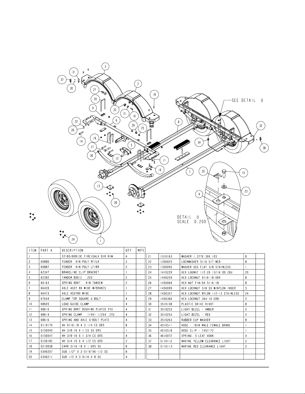
SPRINGS
Position the axles so they are aligned with the trailer.
Position the brake axle so that the disc brake calipers are
on the back side of the axle. The brake axle must always
be mounted as the rear axle to give you the best braking
pos s i b le. T h e re i s no r i ght a n d l e f t to t he a x l e
without brakes. It can be mounted either way.
Plac e the springs on the topside of the sprin g pads
welded to the axle. (See chassis diagram on Page 4).
Note: The hook end of the spring must be to the rear
of the trailer. Place a spring clamp on the top center of
the spring. The 1/2” x 6-1/2” U-bolts are placed down
over the top of the spring clamp, spring and axle.
Place the spring and axle U-bolt plate onto the ends of the
two U-bolts. Secure in place with 1/2” lock nuts. Do not tighten
securely until the adjustments can be made. Repeat on the
other spring.
AXLE
Place one of the spring bracket bushings (Ref. #35) into the
rear of the spring bracket and secure with a 9/16” x 3 1/4” hex
bolt and hex lock nut. Repeat in other spring bracket.
Position the rear axle under the frame, then hook the hook loop of
the spring around the bushings just installed. If the axle is positioned
too low, the hooks will not hook around the bushings.
Raise the front of the springs up so they align with the rear
hole in the axle rocker arm. Secure in place with a 9/16” x
3-1/4” hex bolts and lock nuts.
Install another spring bracket bushing in the front hole on
the rock arm assembly. Secure with a 9/16” x 3-1/4” hex
bolt and lock nut. Tighten.
Hook the hook end of the springs mounted to the front axle over the
bushing in the rocker arm assembly. Swing the front of the
spring up and attach the front mounting hole in the spring bracket with another 9/16” x 3-1/4” hex bolt and lock nut.
Tighten all axle U-bolts and spring bolts.
ONE AXLE BRAKE INSTALLATION
Cut the tape securing the brake line hose to the axle.
Remove the brass plug from the port in the brass block on
the right brake caliper. Thread the brake hose male end into
the port from which the plug was removed and tighten. Place
the other end of the hose up through the hole in the brake
line clip bracket (Ref #29). Secure with the hose clip.
Remove the plastic cap from the end of the frame brake line
coming out of the black plastic tube in the side frame by the
axle. Uncoil the brake line so that it will reach the end of the
hose just attached to the brake line clip bracket. Thread the
brake line fitting into the brake line hose. Tighten. All bleeding to the line can be done through the bleeder on the right
caliper. For bleeding instructions see the ShoreLand’r Brake
Manual.
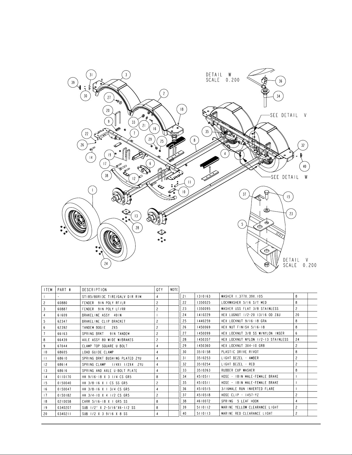
DUAL AXLE BRAKE INSTALLATION
Cut the tape securing the brake line hose to the axle.
Remove the brass plug from the port in the brass block on
the right brake caliper. Thread the brake hose male end
into the block and tighten. Attach the brake hoses from the
axles to the spring bracket with the brake line clip brackets
as shown in Detail U. Once the brake hoses are secured
with the hose clips, the lines can be attached.
Identify which brake line hose that the side frame brake line
tubing will be connected to. In a dual axle installation it can
connected to either one. When identified, locate the brass
tee connector. Screw the male port of the tee into the brake
line hose. Tighten. (See Detail W.) Connect the side frame
brake line into the top port on the tee. Connect the two axles
together using the 40” brake line. Thread one end of the line
into the remaining port in the brass tee. Route the line over to
the other axle, form a loop in the line and connect the other
end into the brake line hose for the second axle.
Fill the actuator reservoir with brake fluid and bleed the line
per the instructions in the ShoreLand’r Brake Manual.
The axle is already bled at the factory during assembly.
Allremainder bleeding of the line can be done through the
bleeder on the right caliper.
Midwest Industries, Inc. Ida Grove, IA 51445 800.859.3028 www.shorelandr.com 0003629
Page 3 3/09/06
Page 4
Tire And Wheel Assemblies
Mount the tire and wheel assemblies using the 1/2” fine
threaded tapered lug nuts provided. Tighten to 80-90
ft/lb. of torque using the rotation pattern as shown in the
Shore Landr’s Owners Manual. Re-torque the lug nuts
after 50 miles of driving and then periodically thereafter.
Note: All nuts and bolts must be tightened before towing.
Single Axle Brake Assembly
Midwest Industries, Inc. Ida Grove, IA 51445 800.859.3028 www.shorelandr.com 0003629
Page 4 3/09/06
Page 5
Tire Size and Carrying Capacity Chart
Tire Size ST185/80R13-C
GVWR 5920 lb.
Carrying Capacity
Axle Brake
4600 lb.
Refer to the tire side wall for correct tire pressure.
Dual Axle Brake Assembly
Midwest Industries, Inc. Ida Grove, IA 51445 800.859.3028 www.shorelandr.com 0003629
Page 5 3/09/06
Page 6
Midwest Industries, Inc. Ida Grove, IA 51445 800.859.3028 www.shorelandr.com 0003629
Page 6 3/09/06
Page 7

B-SERIES BUNK ASSEMBLY
The bunk mounting brackets are assembled on the bunks at
the factory. Place a bunk support pivot on one end of the bunk
support tube and align the holes. Position the end of the bunk
assembly with the two brackets towards the rear of the trailer.
Lower this assembly on the bunk support pivots so the U-bolts
align and go through the holes in the bunk support pivots.
Secure with spacers on the U-bolt legs and 1/2” hex lock nuts.
Repeat procedure. Tighten. (See Detail S, page 1).
The front bracket is not attached to the bunk because the
trailer can be adjusted to two different lengths. Once the proper
position for the rear cross member is determined, the front of the
bunk can now be attached to the bracket using two- No. 10 x 11/4” self tapping screws as shown in Detail H, page 6.
The 3/8” bolts that attach the bunk bracket to the adjustable bunk brac ket on th e front crossmember can
be tighten ed. Do not over tighten, the bu nks should
be allowed to pivot slightly to conform to the boat bottom once the boat is set on the trailer.
Midwest Industries, Inc. Ida Grove, IA 51445 800.859.3028 www.shorelandr.com 0003629
Page 7 3/09/06
WINCH POST ASSEMBLY
The height of the bow eye on your boat will determine the
postion of the winch post. Once this is determined, attach the winch base to the tongue with three 1/2” x 4-1/2”
hex bolts and lock nuts. (See Detail K)
Align the holes in the Profile 2000 mounting channel with the holes in the top of the winch base.
Attach the front of the winch head mounting channel to the base by placing a 1/2” x 4-1/2” hex bolt
through the hole closest to the front of the winch
base. Secure with a lock nut. Do not tighten.
The winch head can be rotated either up or down. Identify the correct hole combination to use to position the bow
eye roller just above the bow eye of your boat. When
determined, secure in this position by placing the bushing inside the winch base so it aligns with the hole just
identified for the proper adjustment. Insert another
1/2” x 4-1/2” hex bolt through the determined mounting hole in the mounting channel and winch base. The
bolt must pass through the bushing. Secure with a 1/2”
lock nut. Tighten all bolts.
Page 8

Midwest Industries, Inc. Ida Grove, IA 51445 800.859.3028 www.shorelandr.com 0003629
Page 8 3/09/06
Page 9

R SERIES
Place the roller arm assembly mounting channel over
the rear cross member and secure with a 1/2” x 4-1/2”
hex bolt and lock nut. (See Detail P). Leave loose until
the boat is placed on the trailer. Tighten after adjustment. Repeat on the other roller arm assembly.
The short stabilizer bunk is installed to the adjustable
bunk bracket on the front cross member with a 3/8” x
1” hex bolt and lock nut. (See Detail N).
Midwest Industries, Inc. Ida Grove, IA 51445 800.859.3028 www.shorelandr.com 0003629
Page 9 3/09/06
Page 10

Midwest Industries, Inc. Ida Grove, IA 51445 800.859.3028 www.shorelandr.com 0003629
Page 10 3/09/06
Page 11

RB SERIES
Locate the two 2 x 6 bunk assemblies. The bunk mounting brackets on the bunk assemblies are mounted at
the factory. Place a bunk support pivot on one end of
the bunk support tube and align the holes. Repeat
on the other end. Lower the assembly on the bunk
support pivots just installed so the U-bolts align and
go through the holes in the bunk support pivots.
Secure by placing first a spacer bushing on the Ubolt leg and then a 1/2” hex lock nut. Tighten. Repeat on the other end of the arm. (See Detail S)
The short stabilizer bunk is installed to the adjustable bunk
bracket on the front cross member with a 3/8” x 1” hex bolt
and lock nut. (See Detail R and Page 10.)
Midwest Industries, Inc. Ida Grove, IA 51445 800.859.3028 www.shorelandr.com 0003629
Page 11 3/09/06
Page 12

Midwest Industries, Inc. Ida Grove, IA 51445 800.859.3028 www.shorelandr.com 0003629
Page 12 3/09/06
Page 13

Midwest Industries, Inc. Ida Grove, IA 51445 800.859.3028 www.shorelandr.com 0003629
Page 13 3/09/06
Page 14

Midwest Industries, Inc. Ida Grove, IA 51445 800.859.3028 www.shorelandr.com 0003629
Page 14 3/09/06
Page 15

Midwest Industries, Inc. Ida Grove, IA 51445 800.859.3028 www.shorelandr.com 0003629
Page 15 3/09/06
Page 16

Midwest Industries, Inc. Ida Grove, IA 51445 800.859.3028 www.shorelandr.com 0003629
Page 16 3/09/06
Page 17

Midwest Industries, Inc. Ida Grove, IA 51445 800.859.3028 www.shorelandr.com 0003629
Page 17 3/09/06
Page 18

Midwest Industries, Inc. Ida Grove, IA 51445 800.859.3028 www.shorelandr.com 0003629
Page 18 3/09/06
Page 19

Midwest Industries, Inc. Ida Grove, IA 51445 800.859.3028 www.shorelandr.com 0003629
Page 19 3/09/06
Page 20

Th e law req uires tha t the whi te
ground wire on both the tongue
wire harness and vehicle harness
be properly grounded to respective
trailer and vehicle frames.
TRAILER ADJUSTMENTS
The fitting of the trailer to your boat is
very important not only for the trailer, but
also the boat. Failure to do so may lead
to potential failure or damage to either
the trailer or boat.
AXLE ADJUSTMENT
The amount of tongue weight on your
trailer can be adjusted as follows:
To lower the tongue weight, adjust the
axle assembly forward. To increase
the tongue weigh t, adjust the axle
assembly backward.
The distance that the axle assembly
has to be moved will vary because it is
directly related to the weight and center
of gravity of the boat place on it.
Best towing is achieved when the
tongue weight is 5-7% of the total
gross load of the complete unit.
NOTE: Brake line and wire harness will
need care when moving the assembly.
REAR SUPPORT SYSTEM
Place the boat on the trailer so that
the transom is located at the rear of
the support system. On an RB bunk
trailer, the transom of the boat should
be within 1-2” of the end of the bunk.
The center of the rear rollers on the
roller rack should be approximately
4” from the transom. This gives you
maximum support on the transom.
The rear cross member is adjustable
forward or backward to allow the trailer
to be adjusted to various length boats.
This is accomplished by removing the
pivot bolt on each end that holds the rear
pivot arm to the side frame and the rear
pivot offset weldments. Once the rear
pivot arm assembly is removed, remove
the two additional bolts on each side
frame that mount the rear pivot offset
weldments to the side frame. Move them
to the desired location and remount
to the side frames with the bolts just
removed. Reposition the rear pivot
arm between the two rear pivot offset
weldments just installed. Secure in
place using the two pivot bolts removed
earlier. Tighten.
Midwest Industries, Inc. Ida Grove, IA 51445 800.859.3028 www.shorelandr.com 0003629
Page 20 3/09/06
The wire harness for the three-light
identification light must be re-positioned
where it comes from the black wire
harness tubing to eliminate slack, and
sagging of the wiring.
BUNKS
Make sure the bunks are positioned far
enough apart to give your boat as much
stability as possible while transporting.
Position the bunks so they are located
just to the outside of the strakes that
your boat may have. This will help
center yo ur boat and ass ist whe n
loading. The bunks need to be adjusted
up high enough to keep the keel from
resting on the center pads. A minimum
of 1” to 2” of clearance is desirable.
RB BUNK trailers would be adjusted the
same way.
ROLLERS
Position the roller racks so they are far
enough apart to give your boat stability
while transporting. When the desired
width is achieved, move the roller rack
system so that the rollers are just to the
outside of the strakes. The rollers need
to be adjusted so that you have a minimum of 1” to 2” of clearance between
the keel of the boat and the center cross
member pads. This will help center the
boat when loading and unloading.
When the desired position is determined, tighten only enough to hold the
bunks or rollers from moving while the
other adjustments are being made.
Final tightening will be done when all
adjustments have been made.
FRONT SUPPORT SYSTEM
BUNK
The front bunks should be adjusted
either in or out so that the bunk will
continue to run just to the outside of the
strakes of the boat. Adjust the bunks up
so that there is approximately 1” clearance between the keel of the boat and
the center cross member pad.
RB AND ROLLER
The keel of the boat must rest on the
center of the front keel roller system
creating a three-point support system.
The keel roller system is designed to
fit most boats without needing any further adjustment. An SS1403 riser kit is
available which will raise the front of
the boat 3/4”.
Once the height of the roller cradle
assembly is established the stabilizer
pads can be adjusted. Slide the pad
up against the boat bottom by hand. It
is not necessary that they carry much
weight. They are designed to give your
boat added stability while being towed.
It may be necessary to adjust the
stabilizer bunks up so that they can be
moved further apart giving additional
support. Pull the assembly away from
the boat. Place the U-bolt that holds
the assembly to the cross member in a
lower hole in the bracket. Then push the
assembly back against the boat. Tighten
in position.
WINCH POST
Slide the winch post base backward on
the tongue until the bow roller comes
in contact with the boat. This bow roller
needs to be positioned directly above
the boat bow eye to prevent your boat
from moving forward in the event of a
sudden stop. It can be moved up or
down by removing the back bolt (1/2” X
4-1/2” hex bolt) that mounts the winch
head to the base. When this bolt is
removed, the head can be rotated up
or down to reach the desired height
required to fit your boat. Once in this
position, align the closest pair of holes
in the brackets and reinsert the bolt
just removed. Tighten. Attach the winch
strap and crank the winch tight.
Attach the bow eye safety chain into the
bow eye of the boat as well. This is just
another level of protection to keep your
boat and trailer together as one unit.
It may also be used to keep your
bo a t o n t h e t ra i l er wh i l e l oa d ing an d u n l o a ding at t h e r a m p ,
especially with a roller trailer.
Adjus t m e n t s are n o w c o m plete.
Re- check your boat for fit. If the desired fit has been achieved, tighten all
fasteners.
All fasteners should be periodically
tightened before towing.
See yo u r Shor e L a n d ’ r O w ner ’ s
Guide for further technical information
re g a r d i n g y o ur t ra i le r an d it ’ s
components.
The law requires that the white ground
wire on bot h the tongue wi re har ness and vehicle harness be properly grounded to respective trailer and
vehicle frames.
 Loading...