

ShoreLand'r SL40TBAL User Manual

®
SLB40TBAL, SLR40TBAL & SLRB40TBAL
Aluminum Trailers
SLB40TBAL
Bundles Required for SLB40TBAL
62340 Literature Bag - Trailers 1
6744300 Frame Bundle, SLB40TBAL 1
4300213 ST175/80R 13C Tire / Galv. Dir Rim 4
SLR40TBAL
Bundles Required for SLR40TBAL
62340 Literature Bag - Trailers 1
6816000 Frame Bundle, SLR40TBAL 1
4300213 ST175/80R 13C Tire / Galv. Dir Rim 4
SLRB40TBAL
Bundles Required for SLRB40TBAL
62340 Literature Bag - Trailers 1
6744700 Frame Bundle, SLRB40TBAL 1
4300213 ST175/80R 13C Tire / Galv. Dir Rim 4
Midwest Industries, Inc. Ida Grove, IA 51445 (800)859-3028 www.shorelandr.com M301237
Page 1

IMPORTANT:
All hardware for your trailer is stainless steel. It is
important that you use an anti-seize material on the bolt
threads when assembling to prevent gaulding.
TONGUE
The tongue comes shipped positioned backwards in the
frame.
Remove the nut and bolt that holds the tongue in place and
discard. Remove the tongue from its shipping position and
install correctly in the front tongue channel.
See pages 4 & 5.
Line the holes in the tongue with the holes in the tongue
channel. Install the 1/2” X 4” hex bolt in the front cross hole
and secure with a 1/2” lock nut.
Remove the wire harness from the rear of tongue. Place the
wire harness and the brake line through the hole provided in
the tongue cover plate. (See Detail F).
Secure the tongue cover plate in position with the same 1/2”
x 1-1/2” hex bolt that secures the back on the tongue to the
tongue channel of the frame.Secure with a 1/2” lock nut.
Tighten both bolts just installed.
Plug the tongue wire harness ends into the frame harnesses
by matching colors and ends. Push the extra wire provided
either into the rear of the tongue or else remove the grommet
in the side frame and place the extra wire in the side frame.
Replace grommets just removed.
White Ground Wire Installation
Place the self-tapping screw provided through the round metal
ring on the white ground wire of the tongue harness located
at the rear of the tongue. Attach the ground wire to the main
frame by driving the screw in the hole provided next to the
tongue channel of the frame. This will assure a positive ground
for the lighting.
Locate the brass brake line coupling. Remove the plastic cap
and thread the brake line coming out the rear of the tongue
into one end of the coupling. Bend the line in a smooth gradual
radius being careful not to kink the line. Bend so it can be
mated to the brake line from the side frame. Once aligned
thread the side frame brake line into the other end of the
coupling. Tighten both lines into the coupling.
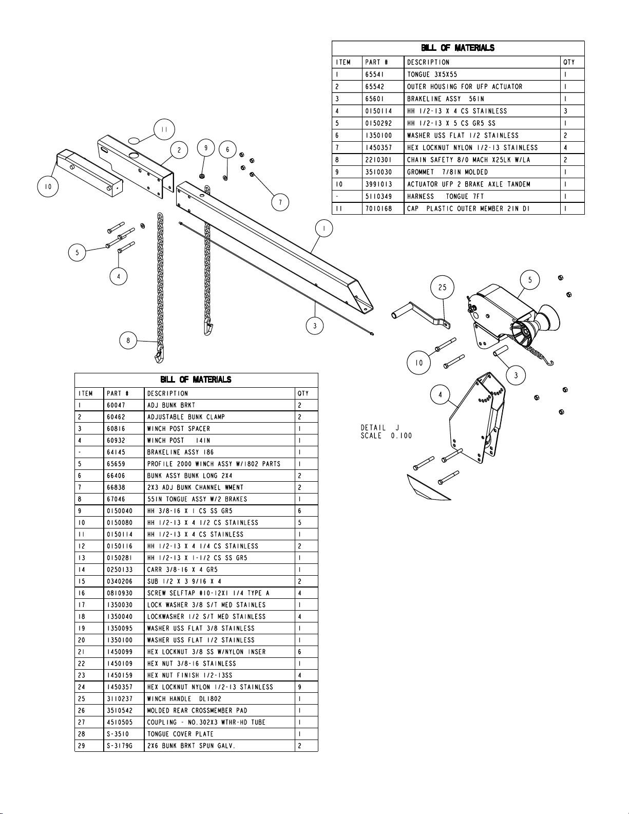
SAFETY CHAINS
Slip the 1/2” x 5” hex bolt through a 1/2” flat washer, place
through the last link of one of the safety chains.
Place the bolt with chain attached through the hole in the
bottom front of the actuator mounted on the tongue.
Position the second chain on the portion of the bolt
extending through the other side of the tongue. Secure with
1/2” flat washer and hex lock nut.
ROCKER ARMS
Locate the rocker arms (Ref. No. 5 of the chassis schematic,
Page 3). Note that the center bushing has a grease zerk in it.
Position the rocker arms up into the center channel welded
in the center of the tandem spring bracket so that the grease
zerk is pointing down. Align the holes in the channel with the
rocker arm. Secure in place with a 3/4” x 4-1/2” hex bolt and
lock nut. Tighten. Repeat this process on the other rocker
arm and spring bracket. Grease the rocker at this time by
applying grease through the zerk just discussed.
NOTE: THE GREASE ZERK IS POSITIONED DOWN SO
THAT IT IS ACCESIBLE FOR SERVICING WHEN NEEDED.
SPRINGS
Position the axles so they are properly aligned with the trailer.
Position the brake axle so that the disc brake calipers are on
the back side of the axle. The brake axle must always be
mounted as the rear axle to give you the best braking
possible (See Page 6). There is no right and left to the axle
without brakes. It can be mounted either way.
Place the springs on the topside of the spring pads welded to
the axle. (See chassis diagram). Note that the hook end of
the spring must be to the rear of the trailer. Place a spring
clamp on the top center of the spring as shown. Next place
the 1/2” x 6-1/2” U-bolts down over the top of the spring clamp,
spring and axle as shown.
Place the spring and axle U-bolt plate onto the ends of the
two U-bolts just placed. Secure in place with 1/2” lock nuts.
Thread onto the U-bolts but do not tighten securely
until the complete unit is in position on the trailer. Repeat on
the other spring.
AXLE
Place one of the spring bracket bushings (Ref.#37) into the
rear of the spring bracket and secure with a 9/16” x 3-1/4”
hex bolt and hex lock nut. Repeat in other spring bracket.
Position the rear axle under the frame, then hook the hook
loop of the springs around the bushings just installed. Note
that if the axle is positioned too low when trying to hook, the
hooks will not hook around the bushings.
Raise the front of the springs up so they align with the rear
hole in the axle boogie just installed. Secure in place with
9/16” x 3-1/4” hex bolts and lock nuts.
Install another spring bracket bushing in the front hole on the
rock arm assembly. Secure with a 9/16” x 3-1/4” hex bolt and
lock nut. Tighten.
Hook the hook end of the springs mounted to the front axle
over the bushing just installed in the rocker arm assembly.
Then swing the front of the spring up and attach the front
mounting hole in the spring bracket with another 9/16” x
3-1/4” hex bolt and lock nut.
Tighten all axle U-bolts and spring bolts.
ONE AXLE BRAKE INSTALLATION
Cut the tape securing the brake line hose to the axle.
Remove the brass plug from the port in the brass block on
the right brake caliper. Thread in the brake hose male end
and tighten. Place the other end of the hose up through the
hole provided in the brake line clip bracket. Secure in place
with the hose clip provided. (Item # 29, Page 6)
Remove the plastic cap from the end of the frame brake line
coming out of the black plastic tube in the side frame by the
axle. Carefully uncoil the brake line so that it will reach the
end of the hose just attached to the brake line clip bracket.
Thread the brake line fitting into the brake line hose. Tighten.
All bleeding to the line can be done through the bleeder on
the right caliper.
Midwest Industries, Inc. Ida Grove, IA 51445 (800)859-3028 ww.shorelandr.com M301237
Page 2
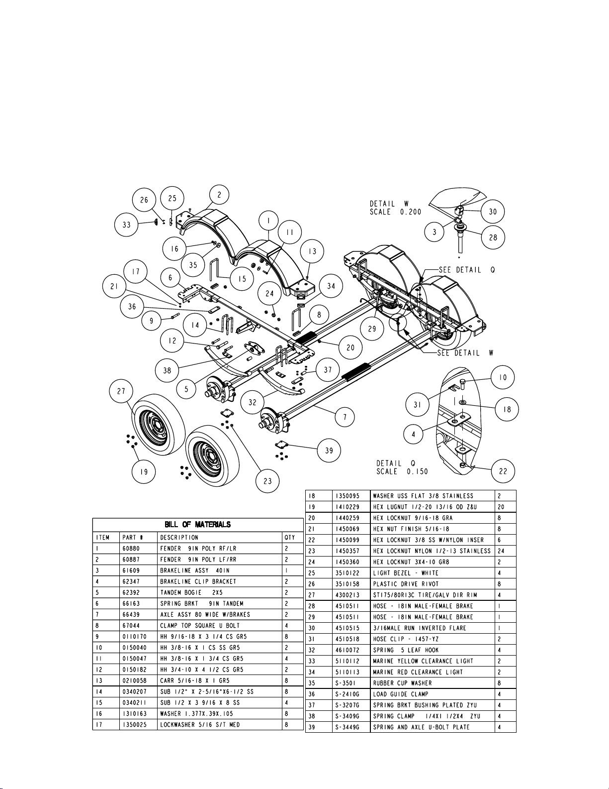
DUAL AXLE BRAKE INSTALLATION
If your trailer is equipped with dual axle brakes connect the
line to the axle as follows:
Cut the tape securing the brake line hose to the axle.
Remove the brass plug from the port in the brass block on
the right brake caliper. Thread the brake hose male end into
the block and tighten. Attach the brake hoses from the axles
to the spring bracket with the brake line clip brackets as shown
in Detail Q. Once the brake hoses are secured in place with
the hose clips (Ref. No. 31) the lines can be attached.
Identify which brake line hose that the side frame brake line
tubing will be connected to. In a dual axle installation it can
connected to either one. When identified, locate the brass
tee connector. Screw the male port of the tee into the brake
line hose. Tighten. Next connect the side frame brake line
into the top port on the tee. Connect the two axle together
using the 40” brake line supplied. Thread one end of the line
into the brass tee just installed. Route the line over to the
other axle, form a loop in the line and then connect the other
end into the brake line hose for the second axle.
Fill the actuator reservoir with brake fluid and bleed the line
per the instructions in the brake manual. Note that the axle is
already bled at the factory during assembly. All bleeding to
the line can be done through the bleeder on the right caliper.
DUAL AXLE BRAKE ASSEMBLY
Midwest Industries, Inc. Ida Grove, IA 51445 (800)859-3028 www.shorelandr.com M301237
Page 3
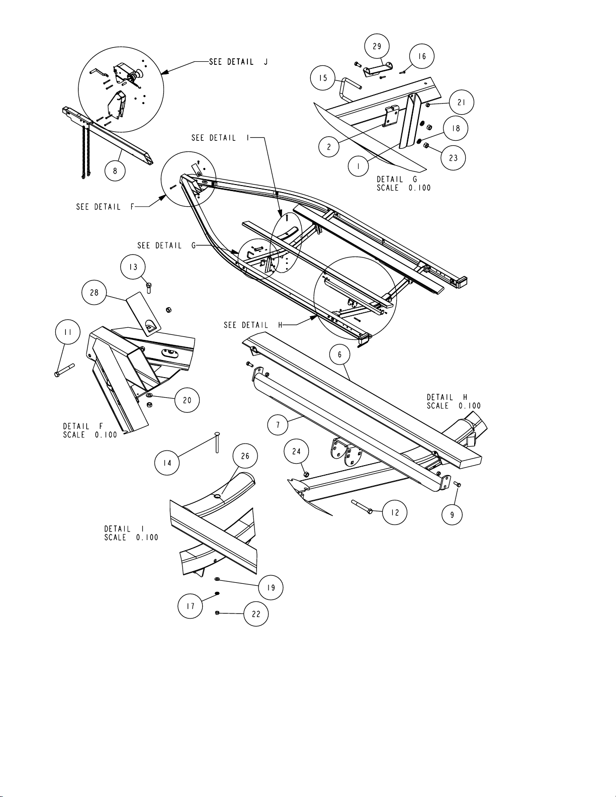
B-SERIES BUNK ASSEMBLY
Locate the two 2 x 6 bunk assemblies. Note that the bunk
mounting brackets are assembled at the factory. Place the
end with the two brackets towards the rear of the trailer. Place
the assembly on the equiload bunk arm and secure by
placing a 3/8” x 1” hex bolt through the bracket on the bunk
and the ear on each end of the equiload arm. Secure in place
using a 3/8” lock nut. Repeat on the other end of the arm.
(See Detail H.)
The front bracket is not attached to the bunk because the
Tire And Wheel Assemblies
Mount the tire and wheel assemblies using the 1/2” fine
threaded tapered lug nuts provided. Tighten to 80-90 ft/lb. of
torque using the rotation pattern as shown in the Shore
Landr’s Owners Manual. Re-torque the lug nuts after 50
miles of driving and then periodically thereafter.
Midwest Industries, Inc. Ida Grove, IA 51445 (800)859-3028 www.shorelandr.com M301237
trailer can be adjusted to two different lengths. Once the
proper position for the rear cross member is determined, the
front of the bunk can now be attached to the bracket using
two- No. 10 x 1-1/4” self tapping screws as shown in Detail G.
The 3/8” bolts can be tightened but not over
tightened because the bunks should be allowed to rotate
slightly to conform to the boat’s bottom.
Page 4
See Page 2 for Tongue and Safety Chain Assembly
Instructions.
WINCH POST ASSEMBLY
(See Detail J). The height that the bow eye is placed in your
boat will determine the length winch post required. Once this
is determined, attach the winch base to the tongue with three
1/2” x 4-1/2” hex bolts and lock nuts.
Align the holes in the Profile 2000 mounting channel with the
holes in the top of the winch base. Attach the front of the
winch head mounting channel to the base by placing a 1/2” x
4-1/2” hex bolt through the hole closest to the front of the
winch base. Secure with a lock nut. Do not tighten.
Note that the winch head can now be rotated either up or
down. Identify the correct hole combination to use to position
the bow eye roller just above the bow eye of your boat. When
determined, secure in this position by placing the bushing as
shown in Detail J inside the winch base so it aligns with the
hole just identified for the proper adjustment. Insert another
1/2” x 4-1/2” hex bolt through the determined mounting hole
in the mounting channel and winch base making sure the
bolt passes through the bushing as well. Secure with a
1/2” lock nut. Tighten all bolts.
Midwest Industries, Inc. Ida Grove, IA 51445 (800)859-3028 www.shorelandr.com M301237
Page 5
 Loading...