

Page 1
®
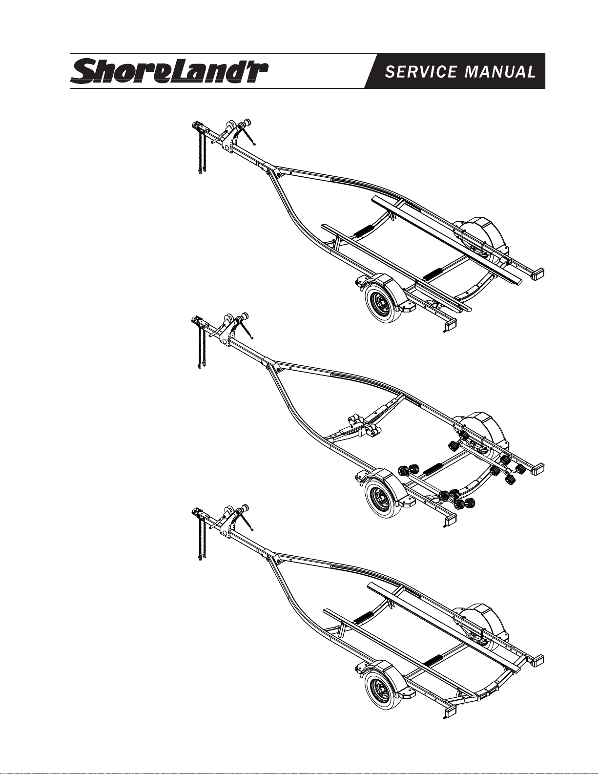
SLB18LN, SLR18LN & SLV18LN
SLB18LN
Bundles Required for SLB18LN
62340 Literature Bag - Trailers 1
68256-- Frame Bundle, 2X3N - Bunk 1
61395 Coupler Bag w/Chains 1
4300213 ST175/80R 13C Tire / Galv. Dir Rim 2
or
4300214 ST175/80R 13C Tire / MSilver Dir Rim 2
SLR18LN
Bundles Required for SLR18LN
62340 Literature Bag - Trailers 1
68257-- Frame Bundle, 2X3N - Roller 1
61395 Coupler Bag w/Chains 1
4300213 ST175/80R 13C Tire / Galv. Dir Rim 2
or
4300214 ST175/80R 13C Tire / MSilver Dir Rim 2
SLV18LN
Bundles Required for SLV18LN
62340 Literature Bag - Trailers 1
68258-- Frame Bundle, 2X3N - V-Frame 1
61395 Coupler Bag w/Chains 1
4300213 ST175/80R 13C Tire / Galv. Dir Rim 2
or
4300214 ST175/80R 13C Tire / MSilver Dir Rim 2
Midwest Industries, Inc. Ida Grove, IA 51445 (800)859-3028 www.shorelandr.com M304285
REV A 9/18/03
Page 1
Page 2
ASSEMBLY INSTRUCTIONS
Remove all items from the frame. Locate the hardware bag and
sort all items by size.
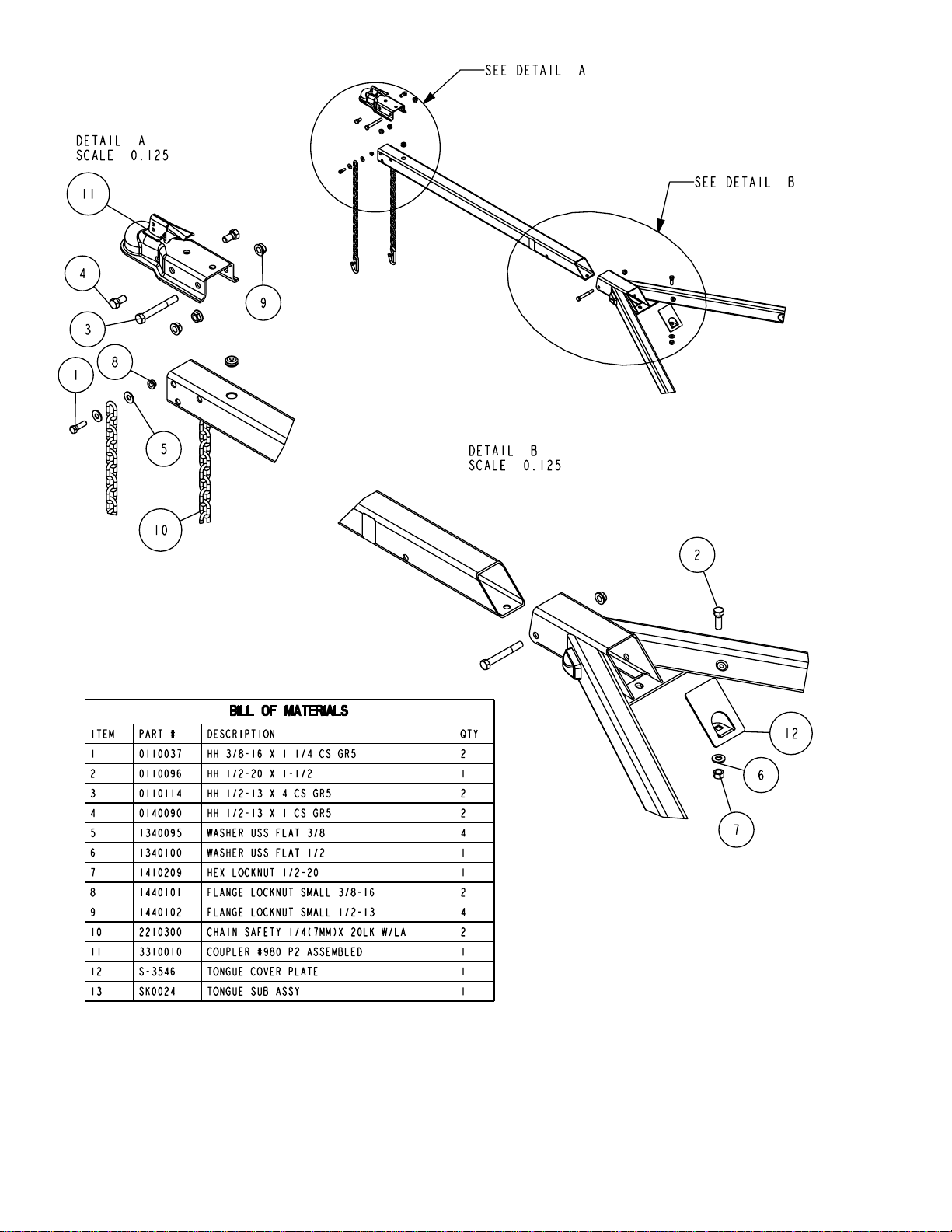
TONGUE
The tongue comes shipped incorrectly in the frame. Slide the tongue
out from it’s shipping position and reinstall in the front tongue
channel. Line the holes in the tongue with the holes in the tongue
channel. Secure with a 1/2” X 4” hex bolt and 1/2” lock nut in the
front cross hole.
Locate the coupler bag. Pace the coupler on the end
of the tongue, align holes and secure with two 1/2” X
4” hex bolts and hex flange lock nuts. Tighten.
WIRE HARNESS
Locate the wire harness. Push the two double plugs
in the hole on the top of the tongue, then out the rear
of the tongue. Place the wire harness through the hole
in the tongue cover plate. (See Detail B) Secure the
tongue cover plate in position with a 1/2” X 1-1/2” hex
bolt and 1/2” lock nut. Tighten. Plug the tongue wire
harness ends into the frame harnesses by matching
colors and ends. Push the extra wire into the rear of
the tongue or remove the grommets in the side frame
and place the extra wire in the side frame. Replace
grommets just removed.
Midwest Industries, Inc. Ida Grove, IA 51445 (800)859-3028 www.shorelandr.com M304285
REV A 9/18/03
Page 2
Page 3
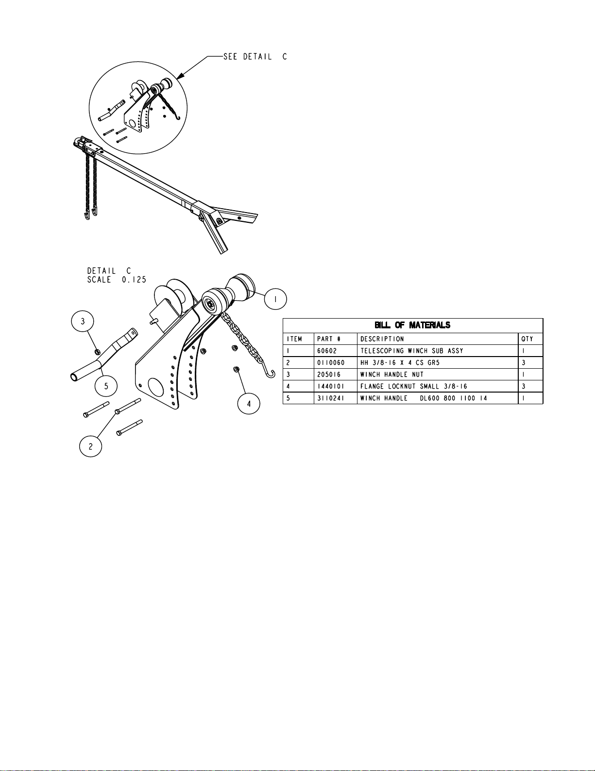
Remove the winch handle nut from the shaft. Align the hole
in the winch handle with the flat surfaces on the shaft. Slide
in position and secure with the nut just removed. Tighten.
SPRINGS
Positions the axle so that it is aligned with the trailer.
Place the springs on the top side of the spring pads welded
to the axle. (See chassis diagram on page 4.) The hook end
of the spring must be mounted to the rear of the trailer. Place
a spring clamp on the top center of the spring. Place the 1/2”
X 6-1/2” U-bolts over the top of the spring clamp, spring and
axle. Place the spring and axle U-bolt plate onto the ends of
the two U-bolts. Secure in place with 1/2” lock nuts. Tighten.
AXLE
Place a spring bracket bushing (Ref.#9, Detail E) into the
rear of the spring bracket and secure with a 9/16” x 3-1/4”
hex bolt and hex lock nut. Repeat in the other spring bracket.
Position the axle under the frame, hook the hook loop of the
spring around the bushings just installed. Note: If the axle is
positioned too low, the hooks will not hook around the
bushings.
WHITE GROUND WIRE
Place the self-tapping screw provided through the round metal
ring on the white ground wire of the tongue harness located
at the rear of the tongue. Attach the ground wire to the main
frame by driving the screw in the hole provided next to the
tongue channel of the frame. This will assure a positive ground
for the lighting.
SAFETY CHAINS
Mount the safety chains to the front of the tongue by placing
a 3/8” flat washer onto a 3/8” X 1-1/4” hex bolt, then insert the
bolt through the last link of the safety chain. Put the bolt
through the hole on one side of the tongue as shown. Place
on another flat washer and secure with a 3/8” hex flange nut.
Tighten. Repeat on the other chain on the other side of the
tongue.
WINCH POST
Place the winch post assembly on the tongue and secure
with three 3/8” X 4” hex bolts and hex flange lock nuts. Place
the nuts on the bolts but do not tighten because they will
have to be readjusted once the boat is on the trailer.
Raise the front of the springs up so they align with the front
hole of the spring bracket. Secure in place with 9/16” X 3-1/
4” hex bolts and lock nuts. Tighten all axle U-bolts and spring
bolts.
TIRE & WHEEL ASSEMBLY
Mount the tire and wheel assemblies using the 1/2” fine
threaded tapered lug nuts provided. Tighten to 80-90 ft./lb. of
torque using the rotation pattern as shown in the
ShoreLandr’s Owners Manual.
Re-torque the lug nuts after 50 miles of driving and then
periodically thereafter.
Midwest Industries, Inc. Ida Grove, IA 51445 (800)859-3028 www.shorelandr.com M304285
REV A 9/18/03
Page 3
Page 4

IMPORTANT: All nuts and bolts must be tightened before
Tire Size: ST175/80R 13-C
GVWR: 2720 lb.
Carrying Capacity: 1800 lbs.
Refer to the tire side wall for correct tire pressure.
Midwest Industries, Inc. Ida Grove, IA 51445 (800)859-3028 www.shorelandr.com M304285
towing.
The law requires that the white ground wire on both the
tongue wire harness and vehicle harness be properly
grounded to the trailer and vehicle frames.
REV A 9/18/03
Page 4
Page 5

SLB18N
BUNK ASSEMBLY (B-SERIES)
The 2 x 4 bunk assemblies have the bunk brackets
factory assembled. Place the end of the bunk with the two
brackets on the equiload bunk arm. (See Detail H) Secure
with 3/8” x 1” hex bolts and lock nuts through the brackets on
the bunk and the ear on each end of the equiload arm.
Place the other end of the bunk in the bracket mounted on
the front cross member. (The bracket is adjustable for height
as well as side ways.) Once the proper position for the rear
Midwest Industries, Inc. Ida Grove, IA 51445 (800)859-3028 www.shorelandr.com M304285
cross member is determined, the front of the bunk can be
attached to the bracket using two No. 10 x 1-1/4” self tapping
screws as shown in Detail I. Repeat assembly on the other
bunk.
The 3/8” bolts can be tightened, but do not over tighten. The
bunks must rotate slightly to conform to the boat bottom.
See Page 8 for final adjustments.
REV A 9/18/03
Page 5
Page 6

SLR18N
ROLLER ASSEMBLY (R SERIES)
Place the roller arm assembly mounting channel over the
rear cross member and secure with a 1/2” x 4-1/4” carriage
bolt and lock nut. (See Detail H). Repeat on the other roller
arm assembly. The roller arm assembly should be left loose
until the boat is placed on the trailer for adjustment. Once the
correct position is determined, tighten.
Midwest Industries, Inc. Ida Grove, IA 51445 (800)859-3028 www.shorelandr.com M304285
REV A 9/18/03
Page 6
Page 7

SLV18N
V-BUNK ASSEMBLY (V-SERIES)
Position the bunks so that they are above the adjustable bunk
brackets attached to the front and rear cross members. (See
Detail J) Secure the brackets on the bunk to the upright
brackets with 3/8” X 1” hex bolts and hex lock nuts. Tighten
but do not over tighten because the bunks must be able to
rotate to conform to the boat bottom.
Midwest Industries, Inc. Ida Grove, IA 51445 (800)859-3028 www.shorelandr.com M304285
REV A 9/18/03
Page 7
Page 8

TRAILER ADJUSTMENTS
Axle Adjustment
The amount of tongue weight on your trailer can be adjusted
as follows: To lower the tongue weight, adjust the axle
assembly forward. To increase the tongue weight, adjust the
axle assembly backward. The distance that the axle
assembly has to be moved will vary because it is directly
related to the weight and center of gravity of the boat placed
on it. Best towing is achieved when the tongue weight is 57% of the total gross load of the complete unit.
NOTE: The wire harness will need care when moving the
assembly.
Rear Support System
Place the boat on the trailer so that the transom is located at
the rear of the support system. On a bunk trailer, the transom
of the boat should be within 1-2” of the end of the bunk. The
center of the rear rollers on the roller rack should be
approximately 4” from the transom. This gives you maximum
support on the transom.
The rear cross member is adjustable forward or backward on
the B & R series trailers to allow the trailer to be adjusted to
various length boats. This is accomplished by removing the
pivot bolts that holds the rear pivot arm to the side frame.
1” clearance between the keel of the boat and the center
cross member pad.
Roller
The keel of the boat must rest on the front keel roller system
creating a three-point support system. The keel roller system
is designed to fit most boats without further adjustment,
however there is considerable difference between boat
bottom designs and certain lines of boats will require the front
cross member to be adjusted up from its normal shipping
position which is the down position.
Determine how high the front cross member will have to be
raised to fit the boat. Note that the front cross member can
be adjusted in four different heights ranging from its down
position to a position where the cross member is flat. Loosen
the two 3/8” X 5” carriage bolts located at the outer end of the
channels of the front roller assembly. (See Detail K, Page 6.)
Remove the two 3/8” X 3” carriage bolts attaching the center
support channel to the front cross member. Raise the
complete assembly up. Align the desired holes in the center
support channel with the holes in the cross frame. Reinsert
the two bolts just removed. Place on the lock nuts removed.
Tighten. Tighten the nuts again on the two bolts loosened at
the ends of the channels of the front roller assembly.
Adjustment is complete.
Once the rear pivot arm assembly is loose, reposition in the
new location. Secure in place using the two pivot bolts
removed earlier. Tighten.
The wire harness for the three-light identification light must
be repositioned to a new hole location in the frame to
eliminate any slack and sagging in the wire.
Rollers
Position the roller racks so they are far enough apart to give
your boat stability while transporting. When the desired width
is achieved, move the roller rack system so that the rollers
are just to the outside of the strake. The rollers need to be
adjusted so that you have a minimum of 1” to 2” of clearance
between the keel of the boat and the cross member pad.
This will help center the boat when loading and
unloading.
When the desired position is determined, tighten only enough
to hold the rollers from moving while the other adjustments
are being made. Final tightening will be done at the end of
the adjusting process.
REAR SUPPORT SYSTEM
Bunks (V & B Series)
The bunks must be positioned far enough apart to give your
boat as much stability as possible while transporting. Position the bunks so they are located just to the outside of the
boat’s strake. This will help center your boat and
assist when loading. The bunks need to be adjusted up high
enough to keep the keel from resting on the center pads. A
minimum of 1” to 2” of clearance is desirable.
FRONT SUPPORT SYSTEM
Bunk
The front bunks should be adjusted either in or out so that
the bunk will continue to run just to the outside of the strake
of the boat. Adjust the bunks up so that there is approximately
Winch Post Adjustment
Slide the winch post assembly back towards the boat. The
bow stop roller needs to be located directly above the boat
bow eye to prevent your boat from moving froward in the
event of a sudden stop.
Note that the outer winch base has several holes of
adjustment. Changing the bolt location will change the angle
of the winch post and will raise or lower the height of the bow
roller. Choose the bolt location which best matches it to the
bow eye height.
The inner and outer winch post channels can telescope
either in or out with respect to each other to lengthen or
shorten the overall length of the post. Loosen the two bolts
located on the back, inside of the channels. Attach the winch
strap into the bow eye and crank the winch strap in until the
bow eye is located in it’s proper position just above the bow
eye. Slide the inner post in or out to a desired length.
Once the bow stop roller is located in it’s proper position above
the bow eye, tighten the bolts that secure the assembly to
the tongue.
Attach the bow eye safety chain into the bow eye as well.
This is another level of protection to keep your trailer and
boat together as one unit. It may be used to keep your boat
on the trailer while loading and unloading at the ramp,
especially with a roller trailer.
Adjustments are now complete. Double check your boat
for fit. If desired fit has been achieved, tighten all fasteners that may have either been left loose or have been
loosened to do the adjusting.
See your ShoreLand’r Owner’s Guide for further
technical information regarding your trailer and its
components.
Midwest Industries, Inc. Ida Grove, IA 51445 (800)859-3028 www.shorelandr.com
REV A 9/18/03
M304285
Page 8
 Loading...