

Page 1
®
Bundles Required
SL150T Aluminum Bunk Trailer - 15000 lbs.
6 4300211 LT 235/85R-16E Tire/Galv Mod Rim
2 66302 Brake Line Kit 8 - Aluminum Tri-axle
1 6627100 Frame Bundle - Aluminum Tri-axle
1 62340 Literature Bag - Trailers
1 3310056 Jack - 2,000 lbs. Drop Leg W/Mtg Hdwe
1 6665100 Hdwe Box for Tandem/Tri - Aluminum
SL150T
Tongue Weight Adjustment
Approximate Tongue Weight for Best Towing.
Tongue weight too high, move the axle assembly forward.
Tongue weight too low, move the axle assembly backward.
Tongue weight should be 5% to 7% of the total gross
weight of the boat and trailer combined.
Tire Size & Carrying
Capacity Chart
Tire Load Carrying
Size Range Capacity
LT235/85R-16 E 3042 lb. per/tire
Refer to tire side wall for proper tire pressure.
NOTE: ShoreLandr offers their product line in either galvanized
or painted finish. When ordering parts it is important that you
specify the finish or color you have on your product. The five digit
number along with a two digit space _ _, notes the parts which can
be purchased with various finishes. When ordering these items
use the five digit prefix and include the following two digit suffix for
proper finish.
Finish / Color Suffix
00 or G Galvanized
01 Arctic White
03 or BK Black
06 or AW Antique White
Cautions/Warnings
The law requires that the white ground wire on the both the
tongue wire harness and the vehicle harness be properly
grounded to the respective trailer and vehicle frames.
Double check all nuts and bolts ---- tighten before towing.
Final Assembly Instructions
Remove the small parts from the frame by cutting the bands.
Remove the bolt bag and sort all nuts and bolts by size.
Refer to following individual pages for assembly instruction by
bundles.
Reference: Standing at the rear of the trailer will determine the
right and left side of the trailer in the assembly instructions.
DECALS:
4810691 TAPE - RED/WHITE CONSPICUITY
4810501 DECAL - LARGE SHORELANDR
4850360 DECAL - NMMA CERTIFIED TRAILER
4810709 DECAL - TRAILER CAUTION/WARNING
4811425 DECAL - PINCH POINT LANDING
Page 2
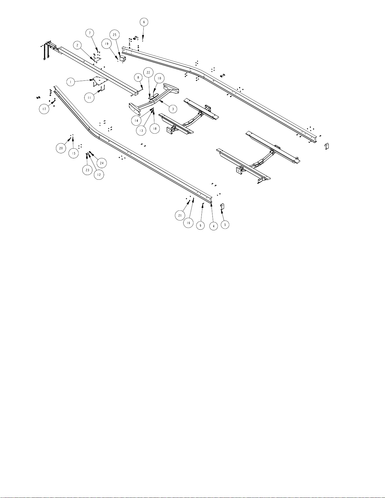
Frame Assembly Instructions
Frame Material List
REF# PART# DESCRIPTION QTY
1 6623800 TONGUE PLATE ....................................... 1
2 6623900 TONGUE PLATE TOP ............................... 1
3 6624500 TONGUE CROSS WMENT ....................... 1
4 66258 SIDEFRAME - ALUMINUM TRIAXLE ....... 2
5 66518 ALUM TRAILER END CAP WMENT ......... 2
6 0150279 HH 1/4-20 X 1 CS SS GR5 ........................ 4
7 0150281 HH 1/2-13 X 1-1/2 CS SS GR5 .................. 16
8 0150286 HH 5/8-11 X 7 CS SS GR5 ........................ 1
9 0150287 HH 5/8-11 X 1-1/2 CS SS GR5 .................. 10
10 0250131 CARR 3/8-16 X 5 SS GR5 ......................... 1
11 0340201 SUB 5/8 X 5 3/4 X 6 1/2 ............................. 2
12 0810971 SCREW SELFTAPPING TYPE A #6X1/2 . 8
13 1350030 LOCKWASHER 3/8 STAINLESS .............. 1
14 1350095 WASHER USS FLAT 3/8 STAINLESS ...... 1
15 1350100 WASHER USS FLAT 1/2 STAINLESS ...... 24
16 1350105 WASHER USS FLAT 5/8 STAINLESS ...... 11
17 1350197 BEVELED WASHER (ALUMINUM) ........... 8
18 1450109 HEX NUT 3/8-16 STAINLESS ................... 1
19 1450356 HEX LOCKNUT NYLON 1/4-20 SS ........... 4
20 1450357 HEX LOCKNUT NYLON 1/2-13 SS ........... 16
21 1450359 HEX LOCKNUT NYLON 5/8-11 SS ........... 15
22 3510542 MOLDED REAR CROSSMEMBER PAD .. 1
23 5110112 MARINE YELLOW CLEARANCE LIGHT .. 4
24 5110369 LIGHT BEZEL SELF GROUND SCREW .. 4
25 5110501 AUSCO TRAILER BATTERY BOX............ 1
Frame Assembly Instructions
Frame:
Your SL95T side frames and crossmembers is assembled at the
manufacturer. The spring brackets and fenders are also moun ted
by the manufacturer.
Battery Box:
Mount the battery box to the right front side frame near the tongue
cap of the SL95T. The battery box will sit flush against the side
frame between the flanges of the side frame i-beam, match the
hole pattern. Secure the battery box to the side frame using four
(4) 1/4 X 1 stainless steel hex head bolts and four (4) 1/4
stainless steel hex lock nuts with nylon inserts.
Actuator:
Mount the brake actuator to the right spring bracket in the hole
pattern designated for the actuator unit. Secure the actuator to the
spring bracket using four (4) 1/4 X 1 stainless steel hex head
bolts and four (4) 1/4 stainless steel hex lock nuts with nylon
inserts. Connect the blue wires.
Wiring:
Run the tongue wire harness through the tongue tube to the rear
and connect to the side frame wire harnesses located at
tehtongue cap on teh first crossmember. With a hooked wire hook the tongue wire harenss and pull wires through the wire only
tongue plate - approximately 30 back on the tongue tube. The
black, brown and white (ground) wires are needed. Push the
remainder of the wires back into the tongue tube. The brown wires
will run to the amber side marker light and plug in. The black wires
will run to the battery box. NOTE: Refer to the wiring instructions
that are available with battery for the connecting procedures. The
white ground wire must be grounded to the trailer frame with a 3/
4 self grounding tap screw. Install grommets inall wire holes.
Refer to page 7 for the vehicle and tongue wire harness connections diagram.
Tongue:
Slide the tongue into the tongue frame cap at the front of the
trailer back into the tongue channel weldment on the front
crossmember. Secure with a 5/8 X 7 stainless steel hex bolt, 5/8
stainless steel flat washer and 5/8 stainless steel hex lock nut
with nylon insert. Secure the tongue inside the tongue cap on the
frame using two (2) 5/8 X 5-3/4 X 6-1/2 square u-bolts and four
(4) 5/8 stainless steel hex lock nut with nylon inserts.
Jack:
NOTE: Remove the hardware provided by the jack manufacturer
and discard. Using the mounting plates provided by the jack
manufacuter, mount the jack on the tongue in a location that best
fits your watercraft. Secure with four (4) 3/8 X 6 stainless steel
hex bolts and four (4) 3/8 stainless steel lock nuts with nylon
inserts located in the hardware bag (66270) within the frame
bundle.
Page 3
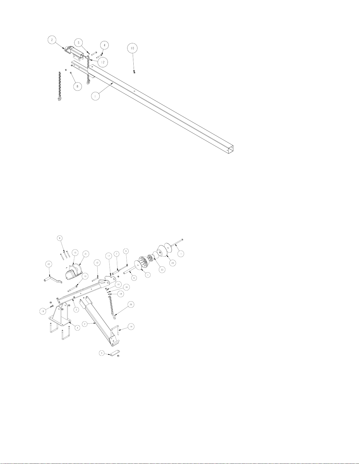
Coupler/Safety Chain Assembly Instructions
Coupler/Safety Chain Assembly Instructions
Coupler:
Mount the coupler onto the tongue (matching the hole pattern)
using two (2) 5/8 X 4-1/2 stainless steel hex bolts and two (2) 5/
8 stainless steel hex lock nuts with nylon inserts.
Safety Chain:
Mount the safety chains to the front of the tongue using a 1/2 X 11/2 stainless steel hex bolt followed by a 1/2 stainless steel flat
washer, safety chain. Secure this assembly on this inside of the
tongue using a 1/2 stainless steel hex lock nut with nylon insert.
Repeat the above instructions on the other side of the tongue.
Tongue/Coupler Material List
REF# PART# DESCRIPTION QTY
1 6618200 TONGUE WMENT ..................................... 1
2 6618500 COUPLER TRI/TAND ALUMALANDR ...... 1
3 0150281 HH 1/2-13 X 1-1/2 CS SS GR5.................. 2
4 0150289 HH 5/8-11 X 4 1/2 CS SS GR5 .................. 2
5 0810973 SCREW SELFDRILL 1/4-14X3/4 SS ........ 1
6 1350100 WASHER USS FLAT 1/2 STAINLESS ...... 2
7 1450357 HEX LOCKNUT NYLON 1/2-13 SS ........... 2
8 1450359 HEX LOCKNUT NYLON 5/8-11 SS ........... 2
9 2210163 CHAIN 3/8(10MM)X 17 LINKS .................. 2
10 3510030 GROMMET 7/8IN MOLDED ..................... 1
11 5110488 TONGUE HARNESS ALUM TRI/TAND .... 1
12 5110500 BRAKE AWAY KIT ALUM TRI/TAND ........ 1
13 5110502 7 PRONG ATV PLUG & 8' PIGTAIL .......... 1
Winch Assembly Instructions
Winch Assembly Instructions
Winch:
Mount the winch assembly to the tongue in a location that best fits
your watercraft. Secure with two (2) 5/8 X 5-3/4 X 6-1/2 square
u-bolts and two (2) 5/8 stainless steel hex lock nuts with nylon
inserts. Place the winch post angle tube on the tongue and secure
using a 5/8 X 5-3/4 X 6-1/2 square u-bolts over the flange. Place
the angle tube base over the legs of the u-bolt and tighten with
two (2) 5/8 stainless steel hex lock nuts with nylon inserts.
Winch Material List
REF# PART# DESCRIPTION QTY
1 6618600 WASHER FLAT PLATE ......................... 2
2 6619100 WINCH POST ANGLE TUBE WMENT . 1
3 6619600 WINCH POST TUBE WMENT ............... 1
4 6619900 WINCH POST BASE WMENT ............... 1
5 6620000 ANGLE TUBE BASE.............................. 1
6 6620100 WINCH POST OUTER ROLLER BUSH 1
7 6631110 UPPER ROLLER ................................... 1
8 0150059 HH 3/8-16 X 3 3/4 CS SS GR5 .............. 3
9 0150280 HH 3/8-16 X 6 1/2 CS SS GR5 .............. 1
10 0150281 HH 1/2-13 X 1-1/2 CS SS GR5 ............. 1
11 0150282 HH 1/2-13 X 10-1/2 CS SS .................... 1
12 0150283 HH 1/2-13 X 6-1/2 CS SS GR5 ............. 1
13 0150286 HH 5/8-11 X 7 CS SS GR5 .................... 1
14 0340201 SUB 5/8 X 5 3/4 X 6 1/2 ........................ 3
15 1350095 WASHER USS FLAT 3/8 STAINLESS .. 3
16 1350100 WASHER USS FLAT 1/2 STAINLESS .. 1
17 1450099 HEX LOCKNUT NYLON 3/8-16 SS ....... 4
18 1450357 HEX LOCKNUT NYLON 1/2-13 SS ....... 3
19 1450359 HEX LOCKNUT NYLON 5/8-11 SS ....... 7
20 2210277 CHAIN 3/16X12 LINK WITH 835 ........... 1
21 3110225 WINCH 3500 WITH STRAP .................. 1
22 3110238 WINCH HANDLE ................................... 1
23 3510576 BOW STOP ROLLER ............................ 1
24 3510577 BOW STOP OUTER ROLLER .............. 2
Page 4

Chassis Material List
REF# PART# DESCRIPTION QTY
1 6020500 BOGIE WEMENT TRIAXLE ................ 4
2 6379500 FENDER SUPPORT ANGLE 3X8 GALV4
3 6448410 SPRING BRACKET BUSHING ZYU ... 2
4 6466400 SPRING SUPPORT CHANNEL ZYU .... 2
5 6625000 SPRING BRACKET WMENT (TRIAX) .. 1
6 6626500 SPRING BRACKET WMENT (TRIAX) .. 1
7 6626700 AXLE ASSEMBLY TRIAXLE/TANDEM . 3
8 6630800 TRIAXLE FENDER ................................ 2
9 0150040 HH 3/8-16 X 1 CS SS GR5 .................... 16
10 0150279 HH 1/4-20 X 1 CS SS GR5 .................... 4
11 0110175 HH 9/16-18 X 4 1/2 CS GR5 ................. 2
12 0110173 HH 9/16-18 X 3 3/4 CS GR5 ................. 10
13 0150288 HH 3/4-10 X 5 1/2 CS SS GR5 .............. 4
14 0250130 CARR 3/8-16 X 1 SS GR5 ..................... 4
15 0810971 SCREW SELFTAP TYPE A #6X1/2 ...... 8
REF# PART# DESCRIPTION QTY
16 1350030 LOCKWASHER 3/8 STAINLESS .......... 4
17 1350095 WASHER USS FLAT 3/8 STAINLESS .. 36
18 1410229 HEX LUGNUT 1/2-20 13/16 OD Z&U .... 40
19 1450099 HEX LOCKNUT NYLON 3/8-16 SS ....... 16
20 1450109 HEX NUT 3/8-16 STAINLESS ............... 4
21 1440259 HEX LOCKNUT NYLON 9/16-18 ........... 12
22 1450356 HEX LOCKNUT NYLON 1/4-20 SS ....... 4
23 1450360 HEX LOCKNUT NYLON 3/4-10 SS ....... 4
24 3510077 3 1/2" X 8" W / 3/8" ROUND CORNERS 4
25 3610117 BUSHING 3/4 IDX1 ODX1 1/2 BRNZ .. 8
26 4300211 LT235/85R-16E TIRE/GALV MOD RIM 6
27 4510639 AUSCO TRLR BRK ACTUATR ASSY... 1
28 5110112 MARINE YELLOW CLEARANCE LITE . 2
29 5110113 MARINE RED CLEARANCE LIGHT...... 2
30 5110369 LIGHT BEZEL SELF GROUND SCRW . 4
Page 5

Chassis Assembly Instructions
Rocker Bushings:
Install the 3/4 ID X 1 OD X 1-1/2 bronze bushings into the inside
the rocker matching the middle and rear hole patterns. The
middle rocker bushing must be secured with a 3/4 X 5-1/2
stainless steel hex bolt through the rocker, bushing and the middle
shackle on the spring bracket. Tighten using a 3/4 stainless steel
hex lock nut with nylon insert. The rear rocker bushing must be
secured with a 9/16 X 3-3/4 hex bolt and 9/16 stainless steel
hex lock nut with nylon insert. Repeat this procedure on the other
rocker on the opposite side of the trailer.
Spring Bracket Bushings:
Install the spring bracket bushing into the spring support channel.
This assembly is then inserted into the rear spring bracket shackle
and secured with a 9/16 X 4-1/2 hex bolt and 9/16 stainless
steel hex lock nut with nylon insert. Repeat this procedure on the
other spring bracket on the opposite side of the trailer.
Axle:
For installation of the front axle: From the outside-in, insert a 9/
16 X 3-3/4 hex bolt through the spring bracket and the eye of the
spring and secure with a 9/16 stainless steel hex lock nut with
nylon insert. Raise the rear of the axle and insert the hook end of
the spring into the rocker box and secure with a 9/16 X 3-3/4 hex
bolt under the spring and tighten with a 9/16 stainless steel hex
lock nut with nylon insert.
For installation of the middle axle: Fromteh outside in insert 9/
16 X 3-3/4 hex bolt through the rear of the rocker box and the
eye of the spring and secure with a 9/16 stainless steel hex lock
nut with nylon insert. Raise the rear of the axle and insert the hook
end of the spring into the rocker box. Ssecure with a 9/16 X 3-3/4
hex bolt under the spring. Tighten with a 9/16 stainless steel hex
lock nut with nylon insert.
For installation of the rear axle: From the outside-in, insert a 9/
16 X 3-3/4 hex bolt through the rear of the rocker box and the
eye of the spring and secure with a 9/16 stainless steel hex lock
nut with nylon insert. Raise the rear of the axle and insert the hook
end of the spring into the spring bracket and secure with the
spring support channel under the spring and secure from the
outside-in with a 9/16 X 4-1/2 hex bolt and 9/16 stainless steel
hex lock nut with nylon insert.
Make certain the hook end of the springs point in the same
direction - to the rear of the trailer, on both axles!
Brakes:
Refer to the brake manual for service and maintenance.
Tire/Rim Assemblies:
Mount the tire and rim assemblies onto the drum using 1/2 lug
hex nuts and tighten to 80-90 ft./lbs. of torque.
Axle Material List
REF# PART# DESCRIPTION QTY
1 6019900 AXLE WMENT TRIAXLE ..................... 1
2 0150290 HH 3/8-24 X 1 CS SS GR5 .................... 10
3 0250133 CARR 3/8-16 X 4 SS GR5 ..................... 1
4 0340204 SUB 1/2 X 2 9/16 X 6 1/2 ...................... 4
5 1310191 TONGUE WASHER 1 3/4OD X 1ID ...... 2
6 1410359 HEX NUT SLOTTED 1-14 PLAIN .......... 2
7 1450099 HEX LOCKNUT NYLON 3/8-16 SS ....... 1
8 1450357 HEX LOCKNUT NYLON 1/2-13 SS ....... 8
9 1450361 HEX LOCKNUT NYLON 3/8-24 SS ....... 10
10 1540038 COTTER KEY 1/8 X 1 1/2 ..................... 2
- 2500011 GREASE OVERBASED CAL SULF ...... 1
11 3510132 AXLE PAD 12IN BLK ............................ 1
REF# PART# DESCRIPTION QTY
- 3510164 STUD COVER 1/2ID X 1 1/2 ................. 1
12 4410091 SPINDLE SLEEVE 2 1/4IN ................... 2
13 4410136 SEAL 2 1/8ID ........................................ 2
14 4410166 ROLLER BEARING ............................... 2
15 4410180 ROLLER BEARING 1 3/4 IN ................ 2
16 4410245 BEARING BUDDY TRIAX ................... 2
17 4510073 12 MARINE BRAKE CLUSTER LEFT ... 1
18 4510074 12 MARINE BRAKE CLUSTER RIGHT 1
19 4510080 12 BRAKE DRUM 8 LUG TRI/TANDEM 2
20 4610077 SPRING 5 LEAF SLIPPER ................... 2
21 S-3387 2" PLASTIC CHANNEL BRACKET ....... 1
22 S-4261G 5/16X4X4 SPRING PLATE ZYU............ 2
Page 6

Front Bunk Assembly Instructions
Front Bunk:
Mount the bunk bracket weldment into the pivot base weldment
using a 5/8 X 4-1/2 stainless steel hex head bolt and secure with
a 5/8 stainless steel hex lock nut with nylon insert. Mount the
bunk assembly onto the bunk bracket weldment using two (2) 1/2
X 1-1/2 stainless steel carriage bolts and secure with a two (2) 1/
2 stainless steel hex lock nuts with nylon insert. Repeat this
procedure on the opposite side of the trailer.
Front Bunk Material List
REF# PART# DESCRIPTION QTY
1 6621300 2X6 BUNK BRACKET............................ 4
2 6621600 BUNK PIVOT BASE WMENT ................ 2
3 6621900 CROSS MEMBER WMENT ................... 1
4 6622300 BUNK BRACKET WMENT (FRONT) .... 2
5 0150289 HH 5/8-11 X 4 1/2 CS SS GR5 .............. 2
6 0250131 CARR 3/8-16 X 5 SS GR5 ..................... 1
7 0250132 CARR 3/8-16 X 1 3/4 SS GR5 ............... 8
8 0250134 CARR 1/2-13 X 1-1/2 SS GR5 .............. 4
9 0340202 SUB 1/2 X 3 9/16 X 5 ............................. 4
10 1350030 LOCKWASHER 3/8 STAINLESS .......... 9
11 1350095 WASHER USS FLAT 3/8 STAINLESS .. 1
12 1450109 HEX NUT 3/8-16 STAINLESS ............... 9
13 1450357 HEX LOCKNUT NYLON 1/2-13 SS ....... 12
14 1450359 HEX LOCKNUT NYLON 5/8-11 SS ....... 2
15 3510542 MOLDED REAR CROSSMEMBER PAD1
16 3910023 BUNKWOOD 2 X 6 X 10FT FIR .......... 2
- 3910170 CARPET 60 IN WIDE BLACK ............... 2
Rear Bunk Assembly Instructions
Rear Bunk Material List
REF# PART# DESCRIPTION QTY
1 6621300 2X6 BUNK BRACKET............................ 4
2 6621600 BUNK PIVOT BASE WMENT ................ 2
3 6621900 CROSS MEMBER WMENT ................... 1
4 6622500 BUNK BRACKET WMENT-LEFT .......... 1
5 6622600 BUNK BRACKET WMENT RIGHT ........ 1
6 0150289 HH 5/8-11 X 4 1/2 CS SS GR5 .............. 2
7 0250129 CARR 1/4-20 X 3/4 SS GR5 .................. 2
8 0250131 CARR 3/8-16 X 5 SS GR5 ..................... 1
9 0250132 CARR 3/8-16 X 1 3/4 SS GR5 ............... 8
10 0250134 CARR 1/2-13 X 1-1/2 SS GR5 .............. 4
11 0340202 SUB 1/2 X 3 9/16 X 5 ............................. 4
12 0810972 SCREW SELFDRILL #10-16X3/4 SS .... 2
13 1350030 LOCKWASHER 3/8 STAINLESS .......... 9
14 1350095 WASHER USS FLAT 3/8 STAINLESS .. 1
15 1450109 HEX NUT 3/8-16 STAINLESS ............... 9
16 1350020 HEX NUT 1/4-20 SS .............................. 4
Rear Bunk:
Mount the bunk bracket weldment into the pivot base weldment
using a 5/8 X 4-1/2 stainless steel hex head bolt and secure with
a 5/8 stainless steel hex lock nut with nylon insert. Mount the
bunk assembly onto the bunk bracket weldment using two (2) 1/2
X 1-1/2 stainless steel carriage bolts and secure with a two (2) 1/
2 stainless steel hex lock nuts with nylon insert. Repeat this
procedure on the opposite side of the trailer.
Wiring:
Run the wiring from the frame outlet to the bunk bracket weldment
and run through the inside and exit out the end of the bunk
bracket weldment. The flex conduit located in the hardware box
will be used to cover the frame wire harness before it enters the
bunk bracket weldment. Install grommets over 3/8 flex conduit in
wire holes on bunk bracket weldment. Using wire ties secure the
flex conduit to the crossmember. Leave the wire until after the
mounting of the taillights on the bunk bracket tube.
Taillights:
Mount the left taillight to the taillight bracket on the bunk bracket
weldment. The license plate bracket will slide between the taillight
and the welded on taillight bracket on the bunk bracket weldment.
Secure with one (1) 1/4 X 3/4 stainless steel carriage bolt and
one (1) 1/4 stainless steel hex nut. Plug wiring that was ran
through the bunk bracket weldment into the taillight wire. Repeat
this same procedure for the right taillight but less the license plate
bracket.
REF# PART# DESCRIPTION QTY
17 1450357 HEX LOCKNUT NYLON 1/2-13 SS ....... 12
18 1450359 HEX LOCKNUT NYLON 5/8-11 SS ....... 2
19 3510030 GROMMET 7/8IN MOLDED ................. 2
20 3510542 MOLDED REAR CROSSMEMBER PAD1
21 3910022 2 X 6 X 8' BUNK MATERIAL ................. 2
- 3910170 CARPET 60 IN WIDE BLACK ............... 3
22 5110001 TAILLIGHT WATERPROOF LEFT ...... 1
23 5110002 TAILLIGHT WATERPROOF RIGHT ... 1
24 5110045 3 LIGHT CLUSTER 1994 LEXAN ....... 1
25 5110348 BO LICENSE PLATE BRACKET ........... 1
-- 1450049 1/4 LOCKWASHER - SS ...................... 4
Page 7

SL150T Accessories and/or Options
ASSEMBLIES AND/OR OPTIONS:
6626700 AXLE ASSEMBLY - TRI-AXLE/TANDEM
6627800 WINCH ASSEMBLY - ALUM TRI-AXLE
6627300 BUNK ASSEMBLY - FRONT
6627400 BUNK ASSEMBLY - REAR
6020600 BOGIE BAG - TRI-AXLE
66270 HARDWARE BAG-TANDEM/TRIAXLE ALUM
66653 HARDWARE BAG - TRI-AXLE (AXLE HDWE)
66298 CUSHION BRACKET ASSEMBLY
Tongue Wiring Diagram - Aluminum Trailers
Page 8

Made in the USA Midwest Industries, Inc. Ida Grove, IA 51445 (800)859-3028 0002876
www.shorelandr.com REV A 11/13/00
 Loading...