

Page 1
®
SLR2313LW
SLR2313LW Bundles Required:
ST185/80R13C MR Tire/MS Dir Rim ..........2
(or)
ST185/80R13C MR Tire/Galv Dir Rim ........2
61395 Coupler Bag with Chains ............................1
62340 Literature Bag - Trailers .............................. 1
80281-- Frame Bundle - 2X4LW Roller ...................1
67757-- Tongue Assembly 55”, Non Brake .............. 1
ShoreLand’r offers their product line in either galvanized or
painted nish. When ordering parts it is important that you
specify the nish or color you have on your product. The ve
(5) digit number along with a two (2) digit space _ _, note the
parts which can be purchased with various nishes. When
ordering these items use the ve (5) digit number along with
a two (2) digit sufx for the proper nish.
00..........Galvanized
01..........Arctic White
03..........Black
33..........Galvanized w/Black Plastic Parts
Table of Contents: Page
Frame Drawing & Bill of Materials ................................2-3
Safety Instructions ........................................................3
Tongue & Safety Chain Dwg/BOM/Assy Instr. ..............4-5
Prole 2000 Winch Dwg/BOM/Assy Instr. ................... 6
Chassis Drawing & Bill of Materials ..............................7
Spring Assembly Instructions ....................................... 8
Axle Assembly Instructions ...........................................8
Tire & Wheel Assembly ................................................8
Tire Size & Carrying Capacity Chart .............................8
Roller Drawings/Assembly Instructions ........................ 9-10
Trailer Adjustments .......................................................11
Axle Adjustments .......................................................... 11
Winch Post Adjustments ...............................................11
Midwest Industries, Inc. Ida Grove, IA 51445 800.859.3028 www.shorelandr.com 0003403
Page 1 REV A 9/01/06
Page 2
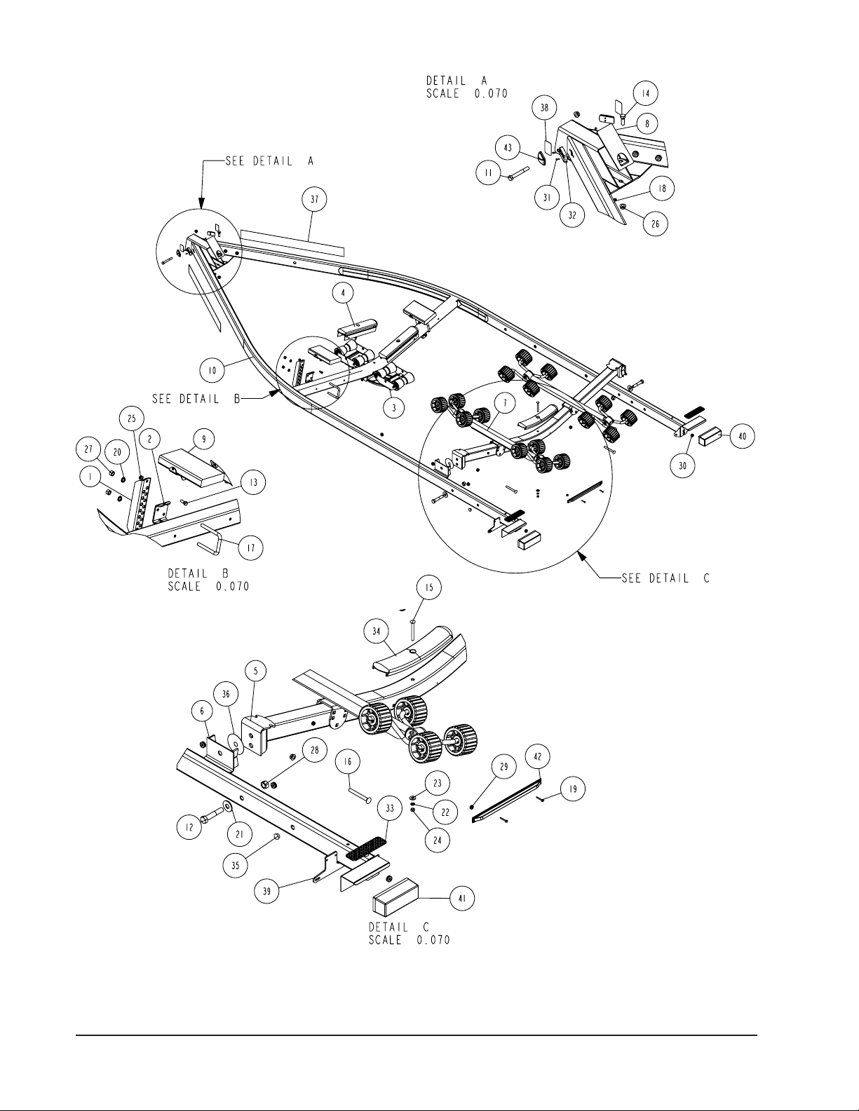
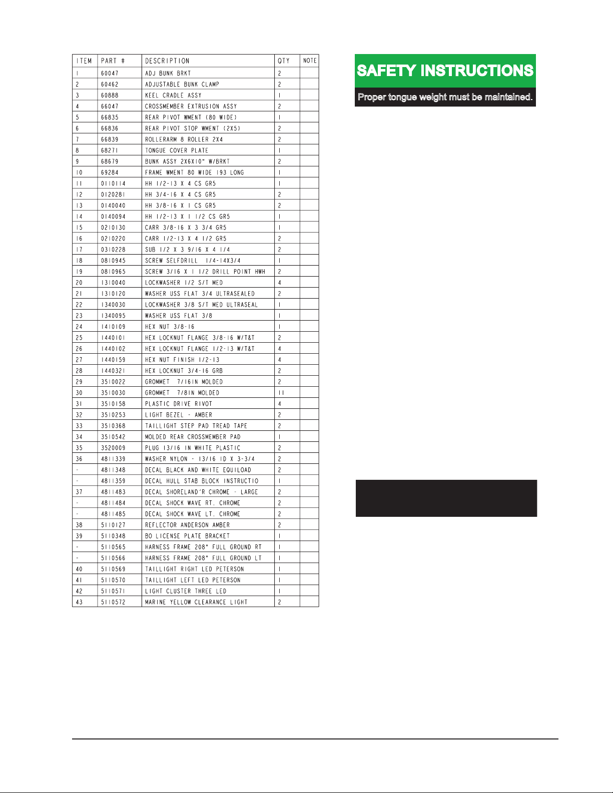
Diagram A
Midwest Industries, Inc. Ida Grove, IA 51445 800.859.3028 www.shorelandr.com 0003403
Page 2 REV A 9/01/06
Page 3
Refer to your ShoreLand’r Owner’s
Guide and other decals on trailer for
additional information.
SAFETY INSTRUCTIONS
4810709
Proper tongue weight must be maintained.
Rev C 8/28/06
Before towing, check the following to ensure
that:
1. All parts, bolts, nuts and wheel lug nuts
are tight.
2. All wheel lug nuts must be tightened to a
minimum torque rating of 85 ft/lb.
3. Lug nuts must be re-torqued after the
first 50 miles, then periodically thereafter.
4. Tires are inflated to manufacturer’s
standards. (See tire sidewall)
5. Wheel bearings have adequate grease.
6. Trailer coupler and coupler ball are the
same size.
7. Hitch ball has a rating that is equal to or
greater than the coupler or actuator
GVWR.
8. Coupler is properly attached and
secured to coupler ball.
9. Trailer safety chains are crossed under
the tongue and attached to towing
vehicle.
10. All lights are operational. Note: It is
recommended that the trailer lights be
disconnected before backing into the
water.
11. Tie downs, winch strap and bow eye safety chain are secure.
12. Trailer tongue jack is in up or travel
position.
Midwest Industries, Inc. Ida Grove, IA 51445 800.859.3028 www.shorelandr.com 0003403
Page 3 REV A 9/01/06
Page 4
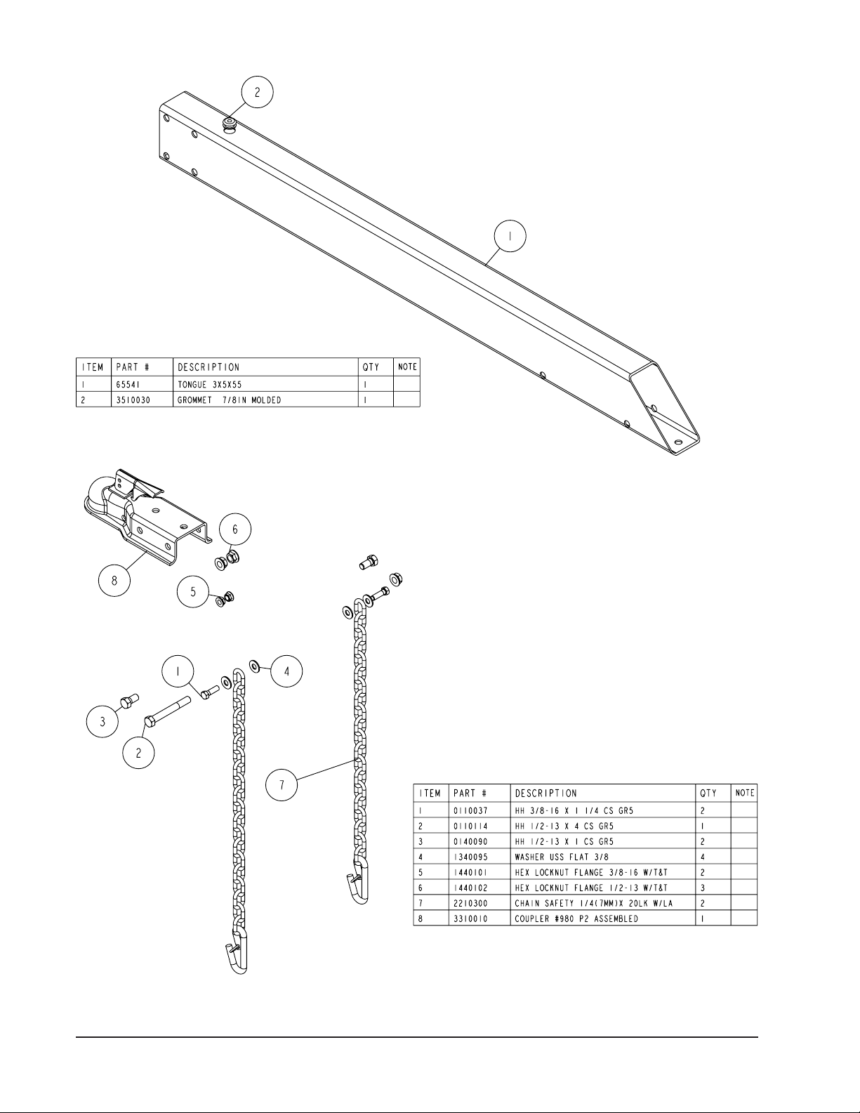
Diagram B
Midwest Industries, Inc. Ida Grove, IA 51445 800.859.3028 www.shorelandr.com 0003403
Page 4 REV A 9/01/06
Page 5

FINAL ASSEMBLY INSTRUCTIONS
Remove the hardware bag from the frame, remove parts and
sort by size.
TONGUE
The tongue is shipped separate of the frame. Locate the
appropriate tongue and install by sliding it in the front of the
tongue channel.
Line the holes in the tongue with the holes in the tongue
channel. Install the 1/2” x 4” hex bolt in the front cross hole
and secure with a 1/2” lock nut.
Remove the wire harness from the rear of the tongue. Place
the wire harness and the brake line (If equipped with brakes)
through the hole provided in the tongue cover plate.
Secure the tongue cover plate in position with the same
1/2” x 1-1/ 2” hex bol t tha t secure s the bac k on the
tongue to the tongue channel of the frame. Secure with
a 1/2” lock nut. Tighten both bolts just installed.
Pl u g th e tongue wir e ha rness end s in to the frame
harnesses by matching colors and ends. Push the extra
wire provided either into the rear of the tongue or else
remove the grommets in the side frames and place the
extra wi re in the side frame. Replace grommets just
removed.
SAFETY CHAINS
Locate the 1/2” x 5” hex bolt. Slip the bolt through a 1/2”
at washer, then place through the last link of one of the
safety chains.
Place the bol t with chai n attac hed through the hole
provided in the bottom front of the actuator mount on the
tongue. Place the second chain on the portion of the bolt
extending through the other side of the tongue. Place on
another 1/2” at washer and hex lock nut. Tighten.
Midwest Industries, Inc. Ida Grove, IA 51445 800.859.3028 www.shorelandr.com 0003403
Page 5 REV A 9/01/06
Page 6

Diagram C
WINCH POST ASSEMBLY
The height that the bow eye is placed in your boat will
determine the length winch post required. Once this is
determined, attach the winch base to the tongue with
three 1/2” x 4-1/2” carriage bolts and lock nuts.
Align the holes in the Prole 2000 mounting channel with
the holes in the top of the winch base. Attach the front of the
winch head mounting channel to the base by placing a 1/2”
x 4-1/2” hex bolt through the hole closest to the front of the
winch base. Secure with a lock nut. Do not tighten.
Note that the winch head can now be rotated either up or
down. Identify the correct hole combination to use to position
the bow eye roller just above the bow eye of your boat. When
determined, secure in this position by placing the bushing as
shown in Diagram C inside the winch base so it aligns with the
hole just identied for the proper adjustment. Insert another
1/2” x 4-1/2” hex bolt through the determined mounting hole
in the mounting channel and winch base making sure the bolt
passes through the bushing as well. Secure with a 1/2” lock
nut. Tighten all bolts.
Midwest Industries, Inc. Ida Grove, IA 51445 800.859.3028 www.shorelandr.com 0003403
Page 6 REV A 9/01/06
Page 7

Diagram D
Midwest Industries, Inc. Ida Grove, IA 51445 800.859.3028 www.shorelandr.com 0003403
Page 7 REV A 9/01/06
Page 8

SPRINGS
Position the axle so it is properly aligned with the trailer.
Place the springs on the top side of the spring pads welded
to the axle. (See chassis diagram). Note that the hook end
of the spring must be mounted to the rear of the trailer. Place
a spring clamp on the top center of the spring as shown.
Next place the 1/2” x 6-1/2” U-bolts down over the top
of the spring clamp, spring and axle as shown.
Place the spring and axle U-bolt plate onto the ends of the
two U-bolts just placed. Secure in place with 1/2” lock nuts.
Thread onto the U-bolts but do not tighten securely until the
complete unit is in position on the trailer. Repeat on the other
spring.
AXLE
Place one of the spring bracket bushings into the rear of
the spring bracket and secure with a 9/16” x 3 1/4” hex bolt
and hex lock nut.
Repeat in other spring bracket.
Position the axle under the frame, then hook the hook
loop of the spring around the bushings just installed.
Note that if the axle is positioned too low when trying to
hook, the hooks will not hook around the bushings.
Tire Size and Carrying Capacity Chart
Tire Size ....................... ST185/80R 13-C
GVWR .......................... 2960 lb.
Carrying Capacity ....... 2300 lb.
Axle .............................. Non-Brake
Refer to the tire side wall for correct tire pressure.
Recommended carrying capacity is based on
shipping weight of the trailer with standard
equipment. Adding optional equipment may
decrease the trailer’s carrying capacity.
Rai s e th e fro n t of t he s p rin g s up s o t h e y a l i g n
wi th the front hole of the spring brack et. Secu re in
place with 9/16” x 3-1/4” hex bolts and lock nuts.
Tighten all axle U-bolts and spring bolts not tightened at this
time.
TIRE & WHEEL ASSEMBLY
Mount the tire and wheel assembli es using the 1/2”
fi ne threa ded tapered lug nuts provide d. Tighten to
80 -90 ft ./lb . of torq ue usi ng the rotat ion patter n as
shown in the ShoreLandr’s Owners Manual.
Re-torque the lug nuts after 50 miles of driving and then
periodically thereafter.
Midwest Industries, Inc. Ida Grove, IA 51445 800.859.3028 www.shorelandr.com 0003403
Page 8 REV A 9/01/06
Page 9

Midwest Industries, Inc. Ida Grove, IA 51445 800.859.3028 www.shorelandr.com 0003403
Page 9 REV A 9/01/06
Page 10

R SERIES
The R-series roller rack is installed by placing the roller arm
assembly mounting channel over the rear cross member
and securing in place with a 1/2” x 4-1/2” hex bolt and lock
nut. (See Diagram A). Note that it should be left loose until
the boat is placed on the trailer. Once the proper positions is
determined, it may be tightened. Repeat on the other
roller arm assembly.
The short stabilizer bunk is installed to the adjustable bunk
bracket on the front cross member with a 3/8” x 1” hex bolt
and lock nut. (See Diagram A).
The adjustment of the trailer to your boat is very important not
only for the trailer, but also the boat. Failure to do so may lead
to potential failure or damage to either the trailer or boat.
Midwest Industries, Inc. Ida Grove, IA 51445 800.859.3028 www.shorelandr.com 0003403
Page 10 REV A 9/01/06
Page 11

TRAILER ADjUSTMENTS
AXLE ADjUSTMENT
The amount of tongue weight on your trailer can be adjusted
as follows:
To lower the tongue weight, adjust the axle assembly
forward. To increase the tongue weight, adjust the axle
backward.
The distance that the axle assembly has to be moved will
vary because it is directly related to the weight and center of
gravity of the boat placed on it.
Best towing is achieved when the tongue weight is 5-7% of
the total gross load of the complete unit.
Note: Wire harnesses and brake line lines (if equipped with
brakes) will need care when moving the axle assembly.
REAR SUPPORT SYSTEM
1. Place the boat on the trailer so that the transom is
located at the rear of the support system. The center of the
rear rollers on the roller rack should be approximately 4”
from the transom. This gives you maximum support on the
transom.
The rear cross member is adjustable forward or backward to
allow the trailer to be adjusted to various length boats. This is
accomplished by removing the pivot bolt on holds each end
of the rear pivot to the side frame. Reposition the rear pivot
arm into the other hole position predrilled in the side frame.
Reattach the rear pivot to the side frame with the bolts just
removed. Tighten.
The wire harness for the three-light identication light must be
repositioned where it comes from the side frame to the rear
pivot to eliminate slack, and sagging of the wiring.
ROLLERS
Position the roller racks so they are far enough apart to give
your boat stability while transporting. When the desired width
is achieved, move the roller rack system so that the rollers
are just to the outside of a strake. The rollers need to be
adjusted so that you have a minimum of one to two inches of
clearance between the keel of the boat and the center cross
member pads. This will help center the boat when loading
and unloading.
When the desired position is determined, tighten only enough
to hold the rollers from moving while the other adjustments
are being made. Final tightening will be done at the end of
the adjusting process.
roller system creating a three-point support system. The keel
roller system is designed to t most boats without needing any
further adjustment, however there is considerable differences
in boat bottom designs and certain lines of boats will require
a riser. One riser is shipped inside the rear keel guide roller
bracket. This can be removed and bolted on the bottom side
of the keel guide roller bracket so it is between it and the keel
cradle itself. This will raise the front end of your boat 3/4”. In
the event that this is not enough, an additional one can be
added to the other keel guide roller bracket.
Once the height of the roller cradle assembly is established
the stabilizer pads can be adjusted. This is accomplished by
sliding the pad up against the boat bottom by hand. It is not
necessary that they carry much weight. They are designed
to just give your boat added stability while being towed. It
may be necessary to adjust the assembly up so that they
can be moved further apart giving additional support. Pull the
assembly away from the boat. Place the U-bolt that holds the
assembly to the cross member in a lower hole in the bracket.
Then push the assembly back against the boat. Tighten in
position.
WINCH POST
1. Once all other adjustments are complete the winch post
can be adjusted. Slide the winch post base backward on the
tongue until the bow roller comes in contact with the boat.
This bow roller needs to be positioned directly above the
boat bow eye to prevent your boat from moving forward in
the event of a sudden stop. It can be moved up or down by
removing the back bolt that mounts the winch head to the
base. When this bolt is removed, the head can be rotated
up or down to reach the desired height required to t your
boat. Once in this position, align the closest pair of holes in
the brackets and reinsert the bolt just removed. Tighten. Attach the winch strap and crank winch tight. Attach the bow
eye safety chain into the bow eye of the boat as well. This is
just another level of protection to keep your boat and trailer
together as one unit.
Adjustments are now complete. Double check your boat for
t. If desired t has been achieved, tighten all fasteners that
may have either been left loose or have been loosened to
do the adjusting.
Note: All nuts and bolts must be tightened before towing. The
law requires that the white ground wire on both the tongue
wire harness and vehicle harness be properly grounded to
respective trailer and vehicle frames.
Recheck all fasteners on the complete trailer to make
sure they are all tight and ready for towing. All fasteners
should be periodically check before towing.
FRONT SUPPORT SYSTEM
ROLLER
The keel of the boat must rest on the center of the front keel
Midwest Industries, Inc. Ida Grove, IA 51445 800.859.3028 www.shorelandr.com 0003403
Page 11 REV A 9/01/06
See your ShoreLand’r Owner’s Guide for further
technical information regarding your trailer and its
components.
Page 12

Midwest Industries, Inc. Ida Grove, IA 51445 800.859.3028 www.shorelandr.com 0003403
Page 12 REV A 9/01/06
 Loading...