

Page 1
®
PWC2213W & PWC2413W
Note; Optional jack and jack mounting hardware are
shown
PWC2213W PWC 2200 Trailer
1 62340 Literature Bag - Trailers
2 *ST175/80R13-C Tire/Dir Rim
1 68218-- Frame Bundle - PWC 2-Place
PWC2413W PWC 2400 Trailer
1 62340 Literature Bag - Trailers
2 *
ST185/80R13C Tire/Dir Rim
1 68218-- Frame Bundle - PWC 2-Place
*Check with your dealer/customer service representative for current tire/rim assembly
part number.
Note; Special attention should be paid when ordering
replacement bunks for these trailers as very carefull
measurements should be taken to insure that the correct
one’s will be sent.
Tire Size & Carrying Capacity Chart
Tire Load Carrying
Size Range Capacity
ST175/80R13 C 1360 lb.
ST185/80R13
ShoreLand’r offers their product line in either galvanized or
painted nish. When ordering parts it is important that you
specify the nish or color you have on your product. The ve
(5) digit number along with a two (2) digit space _ _, note the
parts which can be purchased with various nishes. When
ordering these items use the ve (5) digit number along with
a two (2) digit sufx for the proper nish.
03 .................Black
00 .................Galvanized
C 1480 lb.
Midwest Industries, Inc. Ida Grove, IA 51445 800.859.3028 www.shorelandr.com 0003599
REV C 03/30/2009
Page 1
Page 2

PWC2213W (All Colors) Specications:
Refer to your ShoreLand’r Owner’s
Guide and other decals on trailer for
additional information.
SAFETY INSTRUCTIONS
4810709
Proper tongue weight must be maintained.
Rev C 8/28/06
Before towing, check the following to ensure
that:
1. All parts, bolts, nuts and wheel lug
nuts are tight.
2. All wheel lug nuts must be tightened
to a minimum torque rating of 85 ft/lb.
3. Lug nuts must be re-torqued after the
first 50 miles, then periodically there
after.
4. Tires are inflated to manufacturer’s
standards. (See tire sidewall)
5. Wheel bearings have adequate
grease.
6. Hitch ball is the proper diameter and
has a rating equal to or greater than
the GVWR of the trailer.
7. Coupler is properly attached and
secured to coupler ball.
8. Trailer safety chains are crossed
under the tongue and attached to
towing vehicle.
9. All lights are operational. Note: It is
recommended that the trailer lights
be disconnected before backing into
the water.
10. Tie downs, winch strap and bow eye safety chain are secure.
11. Trailer tongue jack is in up or travel
position.
Capacity: 2200 lbs.
GVWR: 2720 lbs.
GAWR: 2720 lbs.
Ship Wt: 500 lbs.
Frm Size: 2X4 (12 Ga)
Tire Size: ST175/80R 13-C
Rim Size: 13 X 4.5 “J”
Brake: N/A
Coupler: 2”
Suspension: 5 Leaf Hook Springs
PWC2413W (All Colors) Specications:
Capacity: 2400 lbs.
GVWR: 2960 lbs.
GAWR: 2960 lbs.
Ship Wt: 505 lbs.
Frm Size: 2X4 (12 Ga)
Tire Size: ST185/80R 13-C
Rim Size: 13 X 4.5 “J”
Brake: N/A
Coupler: 2”
Suspension: 5 Leaf Hook Springs
Midwest Industries, Inc. Ida Grove, IA 51445 800.859.3028 www.shorelandr.com 0003599
REV C 03/30/2009
Page 2
Page 3
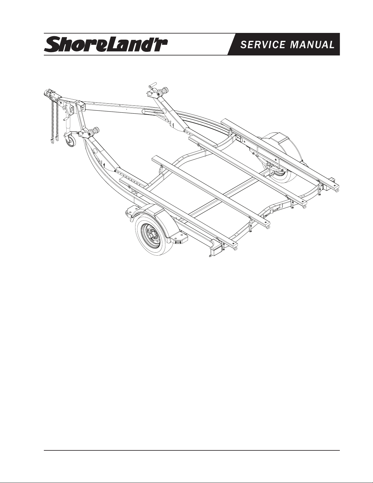
Frame Drawing
Midwest Industries, Inc. Ida Grove, IA 51445 800.859.3028 www.shorelandr.com 0003599
REV C 03/30/2009
Page 3
Page 4
Winch Assembly
Bunk Assembly
Midwest Industries, Inc. Ida Grove, IA 51445 800.859.3028 www.shorelandr.com 0003599
REV C 03/30/2009
Page 4
Page 5

Optional Jack Assembly
Midwest Industries, Inc. Ida Grove, IA 51445 800.859.3028 www.shorelandr.com 0003599
REV C 03/30/2009
Page 5
Page 6

Chassis
Midwest Industries, Inc. Ida Grove, IA 51445 800.859.3028 www.shorelandr.com 0003599
REV C 03/30/2009
Page 6
Page 7

FINAL ASSEMBLY INSTRUCTIONS
Remove all banded items from the frame and sort hardware
by size.
SPRINGS
Position the axle so it is properly aligned with the trailer. Place
the springs on the top side of the spring pads welded to the
axle. (See chassis diagram). Note that the hook end of the
spring must be mounted to the rear of the trailer. Place a
spring clamp on the top center of the spring as shown. Next
place the 1/2” x 6-1/2” U-bolts down over the top of the spring
clamp, spring and axle as shown.
Place the spring and axle U-bolt plate onto the ends of the
two U-bolts just placed. Secure in place with 1/2” lock nuts.
Thread onto the U-bolts but do not tighten securely until the
complete unit is in position on the trailer. Repeat on the other
spring.
AXLE
Place one of the spring bracket bushings into the rear of the
spring bracket and secure with a 9/16” x 3 1/4” hex bolt and
hex lock nut. Repeat in other spring bracket.
Position the axle under the frame, then hook the hook loop
of the spring around the bushings just installed. Note that if
the axle is positioned too low when trying to hook, the hooks
will not hook around the bushings.
Raise the front of the springs up so they align with the front
hole of the spring bracket. Secure in place with 9/16” x 3-1/4”
hex bolts and lock nuts.
Tighten all axle U-bolts and spring bolts not tightened at this
time.
TIRE & WHEEL ASSEMBLY
Mount the tire and wheel assemblies using the 1/2” ne
threaded tapered lug nuts provided. Tighten to 85-95 ft./lb.
of torque using the rotation pattern as shown in the Shore-
Landr’s Owners Manual.
Re-torque the lug nuts after 50 miles of driving and then
periodically thereafter.
WINCH POSTS
The winch posts can be mounted as far forward on the mounting channels as possible until the PWC’s are placed on the
trailer. Attach by placing the 3/8” bolts through the holes in the
bottom of the winch posts and the mounting channels.
Place the winch handles onto the winch drive shafts and se-
cure using the 1/2 “ nuts provided. All other adjustments will
be done after the PWC’s are positioned on the trailer.
OPTIONAL JACK & MOUNTING HARDWARE (Page 5)
The hardware for the optional jack should be included in
the winch base kit box. After opening the bag and sorting
the components place jack inside spacer on the winch
stand base aligning the slots with the holes in the base
and the dimple on the plate in the dimple on the winch
base. Place the jack over this and slide the jack retainer
platin place over the spacer plte aligning the square holes
with the slots in the spacer plate. Insert two (2) 12/ x 1
1/4” carriage bolts and secure on the inside with 1/2” lock
washers and 1/2” hex nuts.
BUNKS: FRONT CROSSMEMBER
Outside PWC bunk brackets on each side of the trailer:
Slide a 3/8” x 3-7/16” x 3” square U-bolt (Item #10, Page 3)
over the front cross member so the threaded end of the U-bolt
is pointing forward. Position the PWC bunk bracket on the
front side of the cross member so that the dog leg end of the
bracket is pointing outward. Align two holes in the PWC bunk
bracket with the legs of the U-bolt, then insert U-bolt through
the holes in the PWC bunk bracket and secure with 3/8” lock
washers and hex nuts. Repeat this process on the other
outside PWC bunk bracket on the front cross member.
Inside PWC bunk brackets on each side of the trailer:
Repeat the above process except point the dog-leg of the
PWC bunk brackets toward the center of the trailer.
BUNKS: REAR CROSS MEMBER
Outside PWC bunk brackets on each side of the trailer:
Slide a 3/8” x 3-7/16” x 3” square U-bolt (Item #10, Page 3)
over the rear cross member so the threaded end of the U-bolt
is pointing rearward. Position the PWC bunk bracket on the
rear side of the cross member so that the dog leg end of the
PWC bunk bracket is pointing outward. Align two holes in
the PWC bunk bracket with the legs of the U-bolt, then insert
U-bolt through the holes and secure with 3/8” lock washers
and hex nuts.
Repeat this process on the other PWC bunk bracket on the
rear crossmember.
Inside PWC bunk brackets on each side of the trailer:
Repeat the above process except point the dog-leg of the
PWC bunk brackets toward the center of the trailer.
Locate the bunk assemblies. Note that one end of the bunks
have a tie down bracket fastened to it.
Position the bunk above the PWC bunk brackets just installed so that the tie down bracket is to the rear of the
trailer. Align the holes in the bunk brackets (Item #2, Page
3) with a hole in the PWC bunk brackets. Note that the PWC
bunk bracket must be on the correct side of the leg of the
bunk bracket attached to the bunk so that the metal of both
brackets will hinge bind themselves when the bunks are pivoted. This will keep the bunks from pivoting too far when the
machines are removed from the trailer. Attach the two
together using 3/8” x 1” hex bolt and 3/8” flange lock
nuts. Tighten but do not over tighten. The bunks must be
allowed to pivot so they can conform to the PWC boat bottom
when it is placed on the trailer. Repeat this process on the
other bunks.
Midwest Industries, Inc. Ida Grove, IA 51445 800.859.3028 www.shorelandr.com 0003599
REV C 03/30/2009
Page 7
Page 8

FINAL ADJUSTMENT:
Place the PWC’s on the trailer so the rear of the machines
are positioned at the rear of the bunks. Check the bunk po-
sitioning for clearance with the strakes. Loosen the U-bolts
securing the PWC bunk brackets to the crossmembers and
slide the bunks either in or out so that they are located just to
the outside of matching strakes. This will not only help with
loading but will also give you proper support for your machine.
Re-tighten the bunks when in the proper location. Repeat on
the other machine.
Note the PWC bunk brackets also have multiple holes for
raising or lowering the position that the machine sets on the
trailer with respect to the frame and fenders. It may require
a change in the height adjustment to clear the fenders on
certain machines.
TRAILERADJUSTMENTS
The adjustment of the trailer to your boat is very important
not only for the trailer, but also the PWC’s. Failure to do so
may lead to potential failure or damage to either the trailer
or PWC’s.
AXLE ADJUSTMENT
The amount of tongue weight on your trailer can be adjusted
as follows:
closest pair of holes in the front of the winch post and the
mounting channel. Insert another bolt in the aligned holes.
Tighten. Attach the winch strap and crank winch tight.
Adjust the winch post for the second PWC as described
above.
Adjustments are now complete. Double check for t. If desired t has been achieved, tighten all fasteners that may
have either been left loose or have been loosened to do the
adjusting.
NOTE: All nuts and bolts must be tightened before towing.
All fasteners should be periodically checked before towing.
See your ShoreLand’r Owner’s Guide for further technical
information regarding your trailer and its components.
To lower the tongue weight, adjust the axle assembly forward. To increase the tongue weight, adjust the axle back-
ward.
The distance that the axle assembly has to be moved will
vary because it is directly related to the weight and center of
gravity of the PWC’s placed on it. The tongue weight is also
dependant on whether your trailer is equipped with a stor-
age box and how much gear you will normally carry in it.
Best towing is achieved when the tongue weight is 5-7% of
the total gross load of the complete unit.
NOTE: Wire harnesses and brake line lines (if equipped with
brakes) will need care when moving the axle assembly.
WINCH POST ADJUSTMENT
Once all other adjustments are complete the winch post can
be adjusted. Slide the winch post backward until the bow
roller comes in contact with the PWC. Align the rear hole
in the bottom of the winch post with the closest hole in the
frame mounting channel. Insert a 3/8” hex bolt into the rear
hole. Position the bow roller directly above the bow eye to
prevent your PWC from moving forward in the event of a
sudden stop. The winch post can be rotated on the rear bolt
just installed until the bow roller is at the desired height required to t your PWC. Once in the correct position, align the
Midwest Industries, Inc. Ida Grove, IA 51445 800.859.3028 www.shorelandr.com 0003599
REV C 03/30/2009
Page 8
 Loading...