

Page 1
PWC2213W & PWC2413W
PWC2213W
1 62340 Literature Bag - Trailers
1 64085-- PWC Walkboard W/Carpet
2 4300241
1 68218-- Frame Bundle
Midwest Industries, Inc. Ida Grove, IA 51445 800.859.3028 www.shorelandr.com 0003599
Page 1 11/17/05
ST175/80R13C Tire/MSilver Dir Rim
PWC2413W
1 62340 Literature Bag - Trailers
1 64085-- PWC Walkboard W/Carpet
2 4300236
1 68218-- Frame Bundle
ST185/80R13C Tire/MSilver Dir Rim
Page 2
Midwest Industries, Inc. Ida Grove, IA 51445 800.859.3028 www.shorelandr.com 0003599
Page 2 11/17/05
Page 3
Midwest Industries, Inc. Ida Grove, IA 51445 800.859.3028 www.shorelandr.com 0003599
Page 3 11/17/05
Page 4

Midwest Industries, Inc. Ida Grove, IA 51445 800.859.3028 www.shorelandr.com 0003599
Page 4 11/17/05
Page 5

Tire Size & Carrying Capacity Chart
Tire Load Carrying
Size Range Capacity
ST175/80R 13 C 2200 lb.
ST185/80R 13 C 2400 lb.
Midwest Industries, Inc. Ida Grove, IA 51445 800.859.3028 www.shorelandr.com 0003599
Page 5 11/17/05
Page 6

FINAL ASSEMBLY INSTRUCTIONS
Remove all banded items from the frame and sort hardware
by size.
Springs:
Install one of the spring bushings Item #96 in the rear of
one of the spring brackets and secure it in place with a
9/16” x 3-1/4” hex bolt and 9/16” flange lock nut. Hook the
hook end of the spring around this bushing and then swing
the front up into the spring bracket. Align the eye of the spring
with the hole provided in the spring bracket and secure in
place with another 9/16” x 3-1/4” hex bolt and 9/16” flange
lock nut. Tighten. Repeat on the other spring.
Axle:
Position the axle under the springs just installed. Align
the pin on the bottom center of the spring with the hole
provided in the spring pad welded to the top of the axle.
Place a spring clamp Item #97 on the topside of the spring.
Drop two 1/2” x 2-5/16” x 6-1/2” U-bolts down over the spring
clamp, spring and then the axle. Place on a spring and axle
U-bolt plate (Item #99) and secure in place with 1/2” flange
lock nuts.
Repeat on the other spring. Tighten all nuts on the U-bolts
just installed.
Tire and Wheel Assemblies:
Mount the tire and wheel assemblies using the 1/2” fine
threaded tapered lug nuts provided. Tighten to 85-95 ft/lb.
of torque using the rotation pattern as shown in the Shore-
Landr’s Owners Manual. Re-torque the lug nuts after 50
miles of driving and then periodically thereafter.
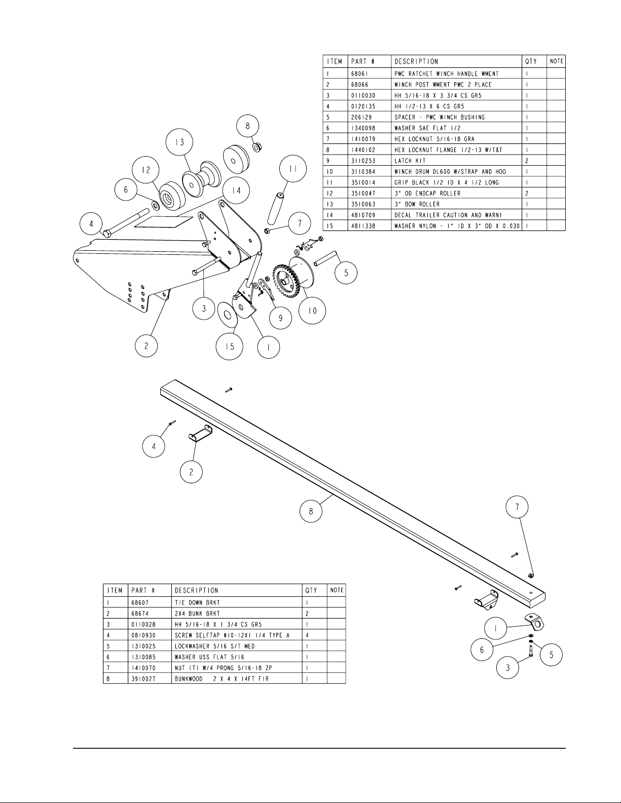
Winch Posts:
Locate one of the winch posts weldments Item #12. Place it
onto the winch post weldment mounting section of the frame
as shown. Note that there is a series of hole positions that
the winch post can be mounted in. Select the one that will
best adapt to your PWC and secure the winch post weldment
to the frame using (2) 3/8” x 3-3/4” hex bolts and flange lock
nuts. Repeat this process on the remaining winch post weldment. Do not tighten at this time because they will have to be
adjusted to the PWC’s once they are placed on the trailer.
Walk Board:
Locate the front walkboard mounting bracket. (Item #3)
Place it on the front of the frame and align the holes in
the bracket with the holes provided in the frame. Mount
the front walkboard bracket to the front of the frame by
placing two (2) 3/8” x 5” carriage bolts in the holes provided from the top side down through the frame. Secure with
3/8” lock washers and hex nuts.
Mount one of the back walk board plates to the middle cross
member by placing 3/8” x 3-1/2” carriage bolts from the top
side down through the plate and cross member.
Place the walkboard down the centerline of the trailer on
top of the walk board mounting brackets just installed.
Ce n t e r on t h e b r a c k e t s si d e w a y s a n d l e n g t h wise. Attac h the walk boa rd to the brack ets by placing No. 10 x 1-1/2” Phillips-head screws in the holes
provided in the mounting brackets from the bottom side up into
the carpeted walkboard. Thread in the screws until tight.
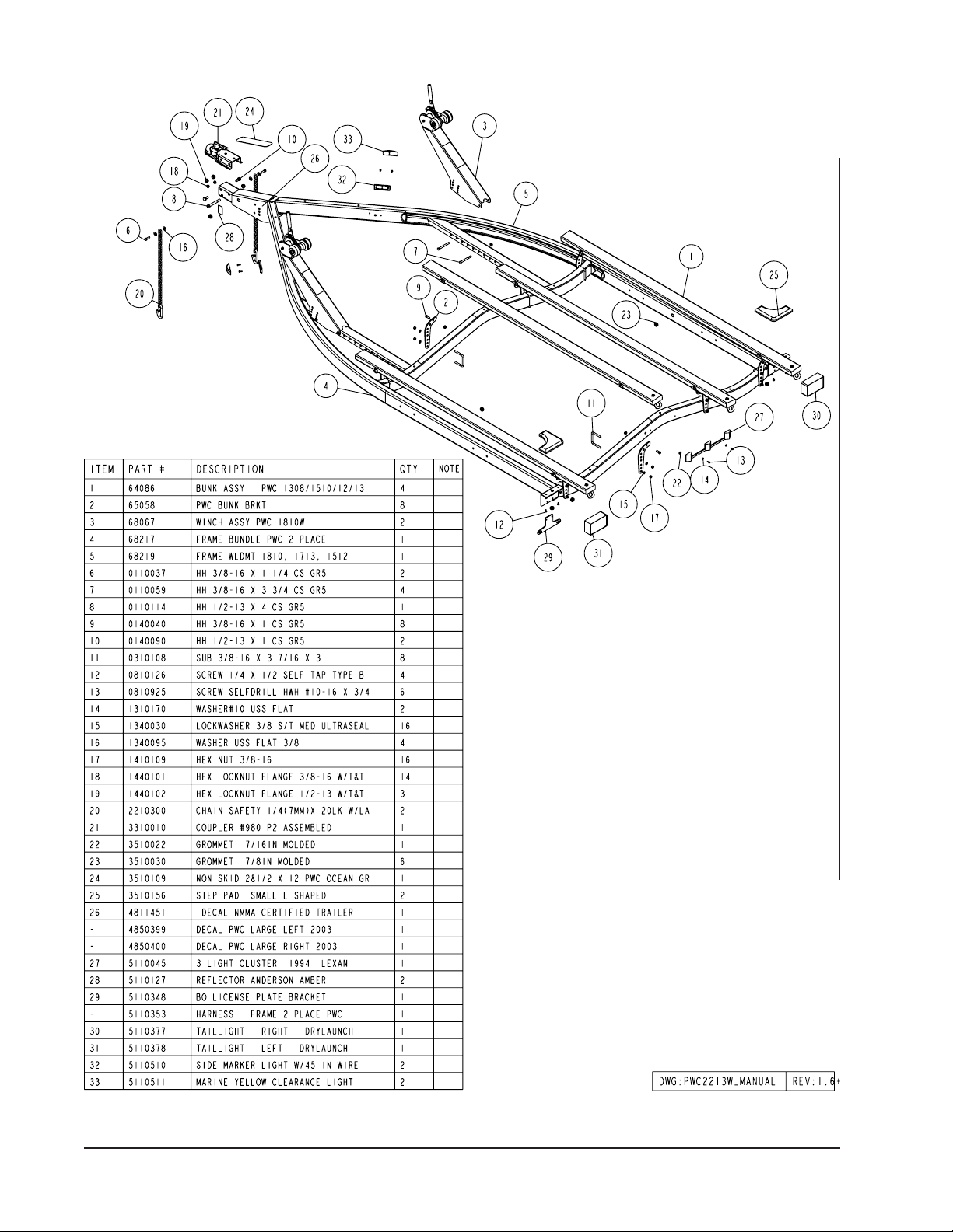
Bunks:
Front Crossmember
Outside PWC bunk brackets on each side of the trailer:
Slide a 3/8” x 3-7/16” x 3” square U-bolt (Item #31) over the
front crossmember so the threaded end of the U-bolt is pointing forward. Position the PWC bunk bracket on the front side
of the cross member so that the dog leg end of the bracket is
pointing outward. Align two holes in the PWC bunk bracket
with the legs of the U-bolt, then insert U-bolt through the holes
in the PWC bunk bracket and secure with 3/8” flange lock
nuts. Repeat this process on the other outside PWC bunk
bracket on the front crossmember.
Inside PWC bunk brackets on each side of the trailer:
Repeat the above process except point the dog-leg of the
PWC bunk brackets toward the center of the trailer.
Rear Crossmember
Outside PWC bunk brackets on each side of the trailer:
Slide a 3/8” x 3-7/16” x 3” square U-bolt (Item #31) over
the rear crossmember so the threaded end of the U-bolt is
pointing rearward. Position the PWC bunk bracket on the
rear side of the crossmember so that the dog leg end of the
PWC bunk bracket is pointing outward. Align two holes in the
PWC bunk bracket with the legs of the U-bolt, then insert Ubolt through the holes and secure with 3/8” flange lock nuts.
Repeat this process on the other PWC bunk bracket on the
rear crossmember.
Inside PWC bunk brackets on each side of the trailer:
Repeat the above process except point the dog-leg of the
PWC bunk brackets toward the center of the trailer.
Lo c ate the bu n k assem b l ies. Not e that one en d of
the bunks have a tie down bracket fastened to it. Posi t ion the bu nk abov e the PWC bu nk brac k ets jus t
installed so that the tie down bracket is to the rear of the trailer.
Align the holes in the bunk brackets (Item #98) with a hole in
the PWC bunk brackets. Note that the PWC bunk bracket must
be on the correct side of the leg of the bunk bracket attached
to the bunk so that the metal of both brackets will hinge bind
themselves when the bunks are pivoted. This will keep the
bunks from pivoting too far when the machines are removed
from the trailer. Attach the two together using 3/8” x 1” hex
bolt and 3/8” flange lock nuts. Tighten but do not over tighten.
The bunks must be allowed to pivot so they can conform to
the PWC boat bottom when it is placed on the trailer. Repeat
this process on the other bunks.
Secure with a 3/8” flange lock nut. Tighten. Repeat this process on the rear crossmember.
Midwest Industries, Inc. Ida Grove, IA 51445 800.859.3028 www.shorelandr.com 0003599
Page 6 11/17/05
Page 7

Final Adjustment:
Place the PWC’s on the trailer so the rear of the machines are
positioned at the rear of the bunks. Check the bunk positioning
for clearance with the strakes. Loosen the U-bolts securing the
PWC bunk brackets to the crossmembers and slide the bunks
either in or out so that they are located just to the outside of
matching strakes. This will not only help with loading but will
also give you proper support for your machine. Re-tighten
the bunks when in the proper location. Repeat on the other
machine.
Note the PWC bunk brackets also have multiple holes for
raising or lowering the position that the machine sets on the
trailer with respect to the frame and fenders. It may require
a change in the height adjustment to clear the fenders on
certain machines.
Winch Post Weldments:
Once the machines are properly positioned on the bunks
the winch post weldments can now be adjusted.
Remove the two 3/8” x 3-3/4” hex bolts installed earlier to
hold the winch post weldment to the frame. Slide the winch
posts weldment either forward of backward so it corresponds
with the front of the machine. Rotate the winch post weldment
so that the bow stop roller is positioned just above the bow
eye of the machine. Attach the winch strap, route under the
bow stop roller, then to the bow eye and tighten the winch
strap slightly to help hold the winch post weldment in position. Locate and align the mounting holes in the winch post
weldment with the holes in the frame member. Re-install the
3/8” x 3-3/4” hex bolts in the new location. Secure with the
3/8” lock nuts removed. Tighten in position.
Pull the machine into the winch post weldment bow eye
roller and check to make sure the positioning is correct. The
bow eye roller must be positioned just above the bow eye to
properly stop the machines in the event of a sudden stop.
The winch strap must run under the bow eye roller when it is
attached to the bow eye.
Repeat the above process on the other machine.
Tongue Weight:
Check the trailer for proper tongue weight. Best towing is
achieved when the tongue weight is 5-7% of the total gross
load of the complete unit.
Axle Adjustment:
The amount of tongue weight on you r trailer can be
adjusted as follows:
To lower the tongue weight, adjust the axle assembly
fo r w a rd, to incre a s e th e tongue weig h t , adjust the
axle assembly backward.
The distance that the axle assembly has to be moved
will vary because it is directly related to the weight and
center of gravity of the machines placed on it.
Re-check all nuts and bolts for tightness to make sure that
none have been missed during assembly. Unit is now ready
to be towed.
Midwest Industries, Inc. Ida Grove, IA 51445 800.859.3028 www.shorelandr.com 0003599
Page 7 11/17/05
Page 8

Midwest Industries, Inc. Ida Grove, IA 51445 800.859.3028 www.shorelandr.com 0003599
Page 8 11/17/05
 Loading...