

Page 1

®
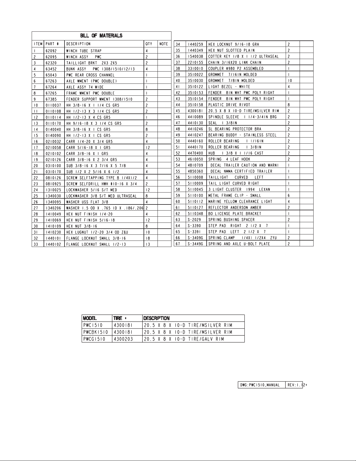
PWC1510, PWC1512 & PWC1513 Parts Manual
PWC1510 PWC 1500# Trailer; White
2 4300181 20.5 X 8 X 10-D Tire/MSilver Mod Rim
1 62340 Literature Bag - Trailers
1 6726801 Frame Bundle - PWC 1510/12/13 - White
PWCG1510 PWC 1500# Trailer; Galvanized
2 4300203 20.5 X 8 X 10-DTire/Galvanized Mod Rim
1 62340 Literature Bag - Trailers
1 6726800 Frame Bundle - PWC 1510/12/13 - Galv.
PWCBK1510 PWC 1500# Trailer; Black
2 4300181 20.5 X 8 X 10-D Tire/MSilver Mod Rim
1 62340 Literature Bag - Trailers
1 6726803 Frame Bundle - PWC 1510/12/13 - Black
PWC1512 PWC 1500# Trailer; White
2 4300184 5.30 X 12-C Tire/MSilver Mod Rim
1 62340 Literature Bag - Trailers
1 6726801 Frame Bundle - PWC 1510/12/13 - White
PWCG1512 PWC 1500# Trailer; Galvanized
2 4300206 5.30 X 12-C Tire/Galvanized Mod Rim
1 62340 Literature Bag - Trailers
1 6726800 Frame Bundle - PWC 1510/12/13 - Galv.
PWCBK1512 PWC 1500# Trailer; Black
2 4300184 5.30 X 12-C Tire/MSilver Mod Rim
1 62340 Literature Bag - Trailers
1 6726803 Frame Bundle - PWC 1510/12/13 - Black
PWC1513 PWC 1500# Trailer; White
2 4300210 ST155/80R13C Tire/MSilver Dir Rim
1 62340 Literature Bag - Trailers
1 6726801 Frame Bundle - PWC 1510/12/13 - White
PWCG1513 PWC 1500# Trailer; Galvanized
2 4300209 ST155/80R13C Tire/Galvanized Dir Rim
1 62340 Literature Bag - Trailers
1 6726800 Frame Bundle - PWC 1510/12/13 - Galv.
PWCBK1513 PWC 1500# Trailer; Black
2 4300210 ST155/80R13C Tire/MSilver Dir Rim
1 62340 Literature Bag - Trailers
1 6726803 Frame Bundle - PWC 1510/12/13 - Black
Service manual effective for models with
VIN numbers after 206205.
Tire Size &
Carrying Capacity Chart
Tire Load Carrying
Size Range Capacity
5.30 X 12 C 1045 lbs. p/tire
ST155/80R13 C 1100 lbs. p/tire
Refer to tire side wall for correct tire pressure.
Tongue Weight Adjustment
Approximate Tongue Weight for Best Towing.
Tongue weight too high, move the axle assembly forward. Tongue
weight too low, move the axle assembly backward. Tongue weight
should be 5% to 7% of the total gross weight of the boat and trailer
combined.
NOTE: ShoreLand’r offers their product line in either galvanized or
painted finish. When ordering parts it is important that you specify
the finish or color you have on your product. The five digit number
along with a two digit space _ _, notes the parts which can be
purchased with various finishes. When ordering these items use the
five digit prefix and include the following two digit suffix for proper
finish.
Suffix Finish / Color
00 or G Galvanized
01 Arctic White
03 or BK Black
Final Assembly Instructions for the PWC1510/1512/1513
Remove the small parts from the frame by cutting the bands.
Remove the bolt bag and sort all the nuts and bolts by size.
Winch Tube Assemblies:
Mount the winch tube assemblies to the frame with 3/8” X 5-7/8”
u-bolts, winch tube straps and 3/8” flange lock nuts.
Axle:
Place one of the spring bushings into the rear of the spring bracket
and secure with a 9/16” X 3-1/4” hex bolt and 9/16” hex lock nut.
Repeat on the other side. Position the axle under the frame, then
hook the spring loop around the bushing just installed. Raise the
axle assembly up so the front of the springs line up with the front
spring bracket hole. Insert the other two (2) 9/16” X 3-1/4” hex bolts
and 9/16” hex lock nuts. Tighten all nuts and bolts, but do not over
tighten. All ow the spring room enough to move.
Mount the tire and rim assemblies with 1/2” lug nuts and tighten to
80-90 ft./lbs. of torque.
Bunks:
Mount the bunk assemblies to the frame with 3/8” X 1” hex bolts in a
location that best fits your watercraft. Secure with 3/8” flange lock
nuts. DO NOT COMPLETELY TIGHTEN FASTENERS. Bunks must
pivot. Leaving the fasteners loose will aid in adjusting your
watercraft to this PWC trailer.
Safety Chain:
Place the two safety chains at the lower front hole on the tongueone (1) chain per side of tongue. Secure with 3/8” X 1-1/4” hex bolts
and 3/8” flat washers. Tighten using 3/8” flat washers and 3/8” flange
lock nuts. Refer to the parts drawing for placement.
Coupler:
Mount the coupler onto the tongue with one (1) 1/2” X 4” hex bolt
rear hole on coupler. Using two (2) 1/2” X 1” hex bolts in the front
most holes - secure the coupler to the tongue using 1/2” flange lock
nuts.
Assembly should be complete except for tightening some of
the bolts. These bolts were left loose to aid in adjusting the
trailer to the watercraft only. All fasteners must be tightened
before towing.
NOTE: The law requires that the white ground wire on both the
tongue wire harness and the vehicle harness be properly
grounded to the respective trailer and vehicle frames.
Page 2
Page 3

42
20
34
30
19
41
39
40
64
Page 4

Parts Drawing
NOTE: Optional equipment and
replacement parts must be
purchased through an authorized
ShoreLand’r dealer.
Page 5

SS1026 WALKBOARD OPTION
ASSEMBLIES:
61987 PWC WALKBOARD W/CARPET
62664 HARDWARE BAG - PWC WALKBOARD
REF# PART# DESCRIPTION .................................................... QTY
1 0210125 3/8” X 2-1/2” CARRIAGE BOLT .......................... 2
2 0210130 3/8” X 3-3/4” CARRIAGE BOLT .......................... 2
3 1340030 3/8” LOCK WASHER ........................................... 2
4 1410109 3/8” HEX FINISH NUT ......................................... 2
5 1440101 3/8” FLANGE LOCK NUT .................................... 2
6 62325 WALKBOARD SPACER CHANNEL - PWC ......... 1
7 61987 PWC WALKBOARD W/CARPET ........................ 1
Page 6

SS1110 ShoreLock’r
Material List for the SS1110
REF# PART# DESCRIPTION QTY
1 3510511 SHORELOCK’R W/LID ........................ 1
2 63058-- CENTER SUPPORT - PWC SC KIT .... 1
3 63059-- REAR SUPPORT - PWC SC KIT ......... 1
4 63083P BUNK ASSY - PWC .............................. 1
5 0210125 3/8” X 2-1/2” CARRIAGE BOLT ............ 4
6 0110059 3/8” X 3-3/4” HEX BOLT ........................ 2
7 0140040 3/8” X 1” HEX BOLT .............................. 6
8 63397-- CROSSMEMBER ANGLE - PWC SC ... 1
9 1340030 3/8” MED. S/T LOCK WASHER ............ 4
10 1340095 3/8” USS FLAT WASHER ..................... 2
11 1410109 3/8” HEX FINISH NUT .......................... 4
12 1440101 3/8” FLANGE LOCK NUT ..................... 6
Assembly Instructions for the SS1110 Storage
Compartment Kit
1. Remove the 3/8” nuts and lock washers from the u-bolt
that holds the winch posts to the main frame. Remove the
bottom support strap from the u-bolt.
2. Install the cross member angle (Ref.#8) to the frame as
shown with the leg of the angle to the front with the u-bolt
that just removed in Step 1. Reinstall the bottom support strap.
Secure in place with the lock washers and nuts just removed.
Do not tighten at this time.
3. Attach the center support walk board bracket (Ref.#2) to
the cross member with two (2) 3/8” X 1” hex bolts and 3/8”
flange lock nuts. Tighten.
4. Place the ShoreLock’r in the frame so the front of the
box is resting on the frame and the rear is resting on the
cross member. Align the holes in the rear of the ShoreLock’r
with the slots in the cross member. Insert two (2) 3/8” X 1”
hex bolts with 3/8” flat washers into the nuts molded into the
ShoreLock’r .
5. Position the front of the ShoreLock’r so that it is in the
center of the frame. Using a 13/32” drill nit, drill holes into the
ShoreLock’r by drilling from the bottom up through the holes
already in the frame. Install the 3/8” X 3-3/4” hex bolts into
the holes just drilled from the bottom up. Secure with 3/8”
flange lock nuts.
Now that he front of the ShoreLock’r is secured to the frame
in the front, position the rear cross member so that the bolts
are positioned in the center of the slotted holes front to rear.
Secure the cross member to the frame by tightening the
u-bolts in Step 2. Tighten the 3/8” X 1” hex bolts that secure
the ShoreLock’r to the cross frame. Note that the bolts
when tightened will allow movement between the
ShoreLock’r and the cross member. This is necessary to
accommodate for the expansion and contraction of the
ShoreLock’r .
6. Install the rear support brackets (Ref.#3) to the rear cross
member of the trailer with two (2) 3/8” X 1” hex bolts and lock
nuts. Do not tighten. Mount the front of the walk board onto
the center support bracket using 3/8” lock washes and hex
nuts. Secure the rear support bracket into position and
secure with the bolts installed in the walk board and 3/8”
lock washers and hex nuts. Tighten all bolts at this time.
7. Your ShoreLock’r has been designed so that the lid may
be locked to the main body by placing a padlock through the
hole in the latch installed in the front of the ShoreLock’r.
Your ShoreLock’r should be locked at all times to prevent
theft.
8. Your ShoreLock’r is equipped with a snap tighten
expandable plug.
9. Your ShoreLock’r is designed to carry approximately
100-125 pounds of gear. Exceeding this amount will void all
warranty and may cause damage to your ShoreLock’r..
Midwest Industries, Inc. Ida Grove, IA 51445 (800)859-3028 www.shorelandr.com 0002865
 Loading...