

Page 1
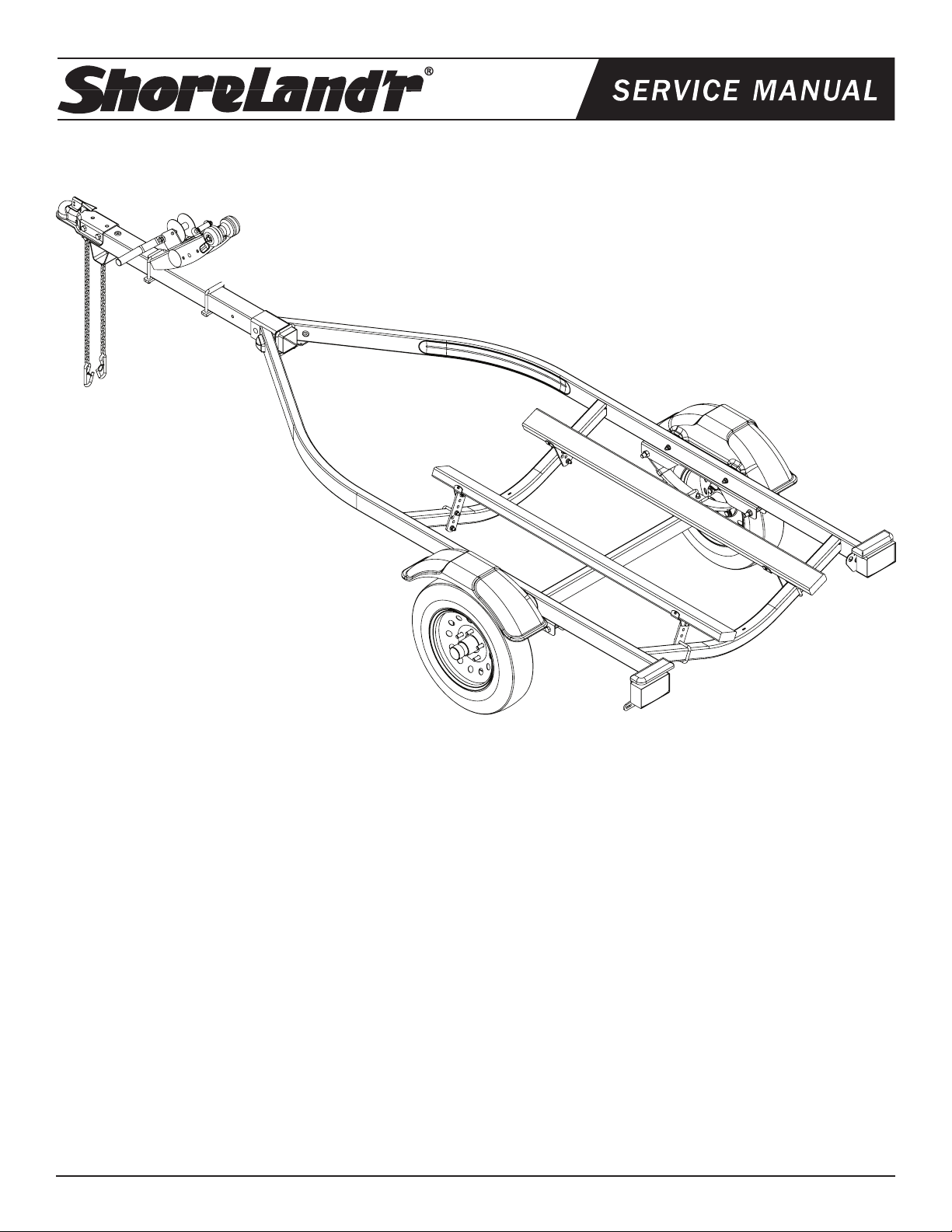
PWC12STS
PWC12STS Bundle Requirements
62340 Literature Bag - Trailers 1
69125 Hardware Box - Single PWC 1
80458-- Frame Bundle PWC1200S 1
4.80 X 12B Tire/Mod Rim 2
62484-- Tongue 42” Single - PWC 1
Midwest Industries, Inc. Ida Grove, IA 51445 800.859.3028 www.shorelandr.com 0003709
Page 1 REV B 07/06/09
Table of Contents: Page
Bundles Required ........................................................ 1
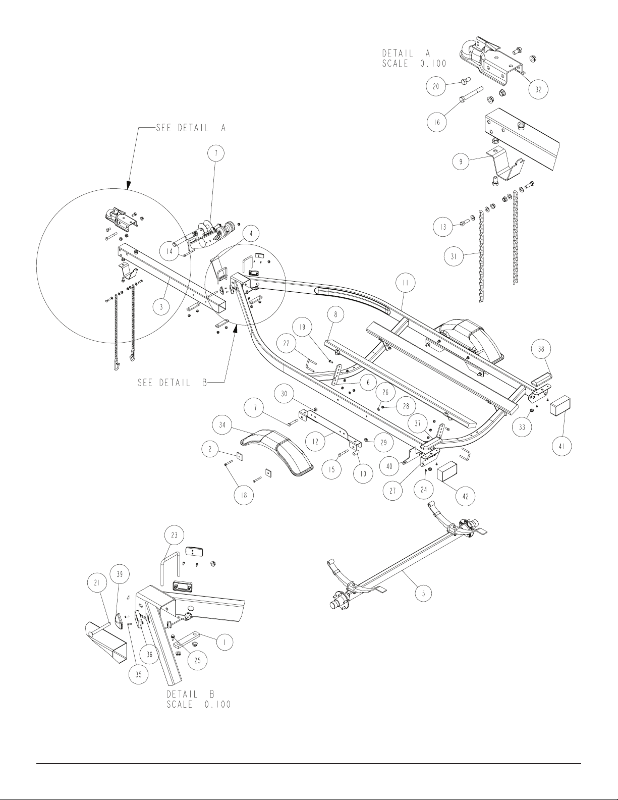
Trailer Drawing & Bill of Materials ............................... 2-3
Color Code Information ............................................... 3
Safety Instructions ....................................................... 3
Tongue Assembly Instructions. .................................... 4
Safety Chain Assembly Instructions ............................ 4
Coupler Assembly Instructions .................................... 4
Winch Post Assembly Instructions............................... 4
Axle Assembly Instructions .......................................... 4
Bunk Assembly Instructions......................................... 4
Misc. Information ......................................................... 4
Tongue Weight Adjustment ......................................... 4
Winch Dwg/BOM ......................................................... 5
Axle Dwg/BOM ............................................................ 6
Tire Size & Carrying Capacity Chart ............................ 6
Bunk Dwg/BOM ........................................................... 7
Page 2
Midwest Industries, Inc. Ida Grove, IA 51445 800.859.3028 www.shorelandr.com 0003709
Page 2 REV B 07/06/09
Page 3
Refer to your ShoreLand’r Owner’s
Guide and other decals on trailer for
additional information.
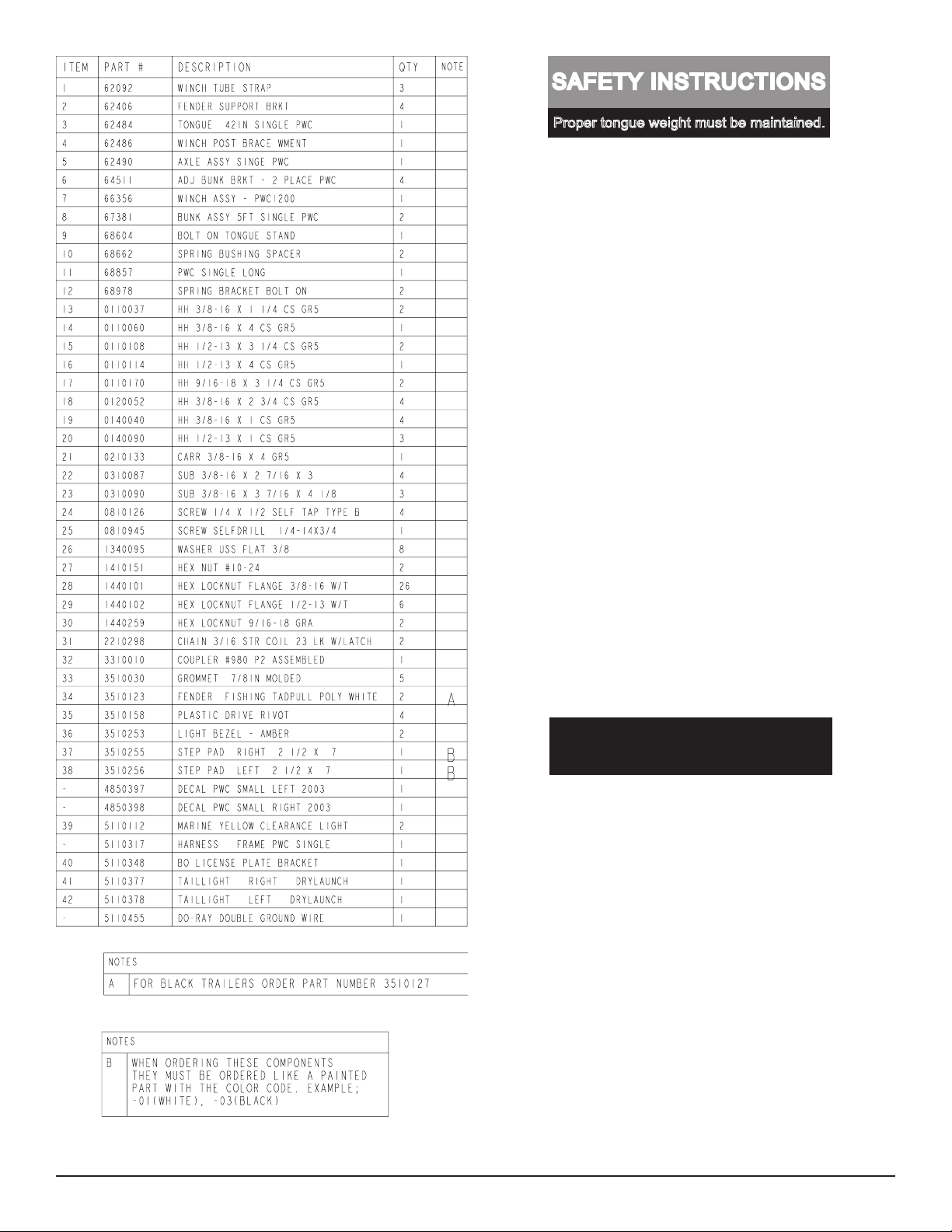
SAFETY INSTRUCTIONS
4810709
Proper tongue weight must be maintained.
Rev C 8/28/06
Before towing, check the following to ensure
that:
1. All parts, bolts, nuts and wheel lug
nuts are tight.
2. All wheel lug nuts must be tightened
to a minimum torque rating of 85 ft/lb.
3. Lug nuts must be re-torqued after the
first 50 miles, then periodically there
after.
4. Tires are inflated to manufacturer’s
standards. (See tire sidewall)
5. Wheel bearings have adequate
grease.
6. Hitch ball is the proper diameter and
has a rating equal to or greater than
the GVWR of the trailer.
7. Coupler is properly attached and
secured to coupler ball.
8. Trailer safety chains are crossed
under the tongue and attached to
towing vehicle.
9. All lights are operational. Note: It is
recommended that the trailer lights
be disconnected before backing into
the water.
10. Tie downs, winch strap and bow eye safety chain are secure.
11. Trailer tongue jack is in up or travel
position.
ShoreLand’r offers their product line in either galvanized or painted
nish. When ordering parts it is important that you specify the nish
or color you have on your product. The ve (5) digit number along
with a two (2) digit space _ _, note the parts which can be purchased
with various nishes. When ordering these items use the ve (5) digit
number along with a two (2) digit sufx for the proper nish.
00..........Galvanized
01..........White
03..........Black
Midwest Industries, Inc. Ida Grove, IA 51445 800.859.3028 www.shorelandr.com 0003709
Page 3 REV B 07/06/09
Page 4

Assembly Instructions:
Remove the small parts from the frame by cutting the banding. Remove the bolt bag and sort all the nuts and bolts by size.
Tongue: (Note: The tongue has two hole positions.)
Slide the tongue into the tongue channel to the hole location that
best ts your boat to trailer set-up. Secure with a 3/8” X 4” carriage bolt in the front and 3/8” X 3-7/16” X 4-1/8” square U-bolt, 1”
X 4-1/2” mounting strap and 3/8” ange lock nut in the rear of the
assembly. Thread the tongue wire harness through the tongue and
connect to the frame harness. Install grommets.
Safety Chain:
Insert a 3/8” X 1-1/4” hex bolt with a 3/8” at washer and safety
chain through the lower hole on the front of the tongue. Secure with
a 3/8” ange lock nut. Repeat this procedure on the opposite side
of the tongue.
Coupler:
Mount the coupler onto the tongue with one (1) 1/2” X 4” hex bolt
and two (2) 1/2” X 1” hex bolts. Secure with 1/2” ange lock nuts.
Winch Post:
Attach the winch brace to the winch post assembly with a 3/8” X 4”
hex bolt in one (1) of the three (3) holes of adjustment. Position the
winch assembly on the tongue in the desired position and fasten
with a 3/8” X 3-7/16” X 4-1/8” square U-bolts, 1” X 4-1/2” mounting
straps and 3/8” ange lock nuts.
CAUTION:
To prevent damage to your water vehicle hull, place the water vehicle on the trailer, loosen bunk U-bolts so the bunks conform to
the hull. Tighten.
Tighten all fasteners before towing.
The law requires that the white wire on both the trailer and vehicle
wire harness be grounded to the trailer and towing vehicle.
Tongue Weight Adjustment
The tongue weight should be 7% to 10% of the total gross weight
of the trailer and boat combined.
The tongue weight can be increased by moving the axle backward
or decreased by moving the axle forward. Loosen and remove the
bolts securing the fenders and spring brackets to the side frame,
reposition the axle and then reinstall in the new location using the
bolts just removed.
Axle:
Install the spring bushing in the rear spring brackets with 1/2” X 3-
1/4” hex bolts and 1/2” ange lock nuts. Position the axle under the
trailer with the spring eye to the front. Slip the at end of the spring
in the rear spring bracket over the bushing and fasten the front
spring eye to the front of the spring bracket with 9/16” X 3-1/4” hex
bolts and 9/16” hex lock nuts.
Mount the tire and rim assemblies with 1/2” lug nuts and tighten to
85-95 ft./lbs. of torque.
Bunk:
Slide a 3/8” X 2-7/16” X 2-3/4” square bolt over the rear cross member with the threads facing the FRONT. Place an adjustable bunk
bracket on the U-bolt legs and secure with 3/8” ange lock nuts.
Slide on a 3/8” X 2-7/16” X 2-3/4” square U-bolt over the front cross
member with the threads facing the REAR. Place an adjustable
bunk bracket on the U-bolt legs and secure with 3/8” ange lock
nuts. Fasten the bunk assembly to the adjustable bunk brackets
just mounted and secure with 3/8” X 1” hex bolts and 3/8” ange
lock nuts.
Midwest Industries, Inc. Ida Grove, IA 51445 800.859.3028 www.shorelandr.com 0003709
Page 4 REV B 07/06/09
Page 5

Midwest Industries, Inc. Ida Grove, IA 51445 800.859.3028 www.shorelandr.com 0003709
Page 5 REV B 07/06/09
Page 6

Tire Size & Carrying Capacity Chart
Tire Size: 4.80 X 12
Load Range: B
Carrying Capacity: 780 lbs. per/tire
Midwest Industries, Inc. Ida Grove, IA 51445 800.859.3028 www.shorelandr.com 0003709
Page 6 REV B 07/06/09
Page 7

Midwest Industries, Inc. Ida Grove, IA 51445 800.859.3028 www.shorelandr.com 0003709
Page 7 REV B 07/06/09
Page 8

Midwest Industries, Inc. Ida Grove, IA 51445 800.859.3028 www.shorelandr.com 0003709
Page 8 REV B 07/06/09
 Loading...