

Page 1
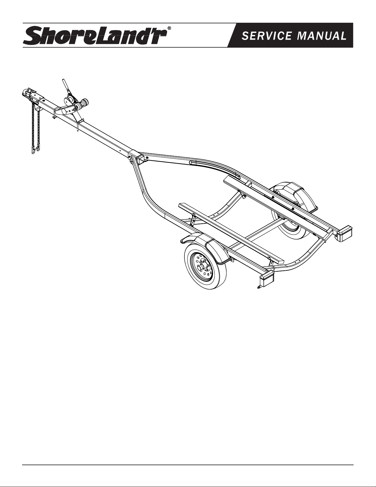
PWC1000L
Bundles Required for PWC1000L
62340 Literature Bag - Trailers 1
80458-- Frame Bundle - PWC1000L 1
4.80x12B Tire / Mod. Rim 2
65265-- Tongue Assy - 65” 1
69125 Box Hardware Single PWC 1
ShoreLand’r offers their product line in either galvanized or painted
finish. When ordering parts it is important that you specify the finish
or color you have on your product. The five (5) digit number along
with a two (2) digit space _ _, note the parts which can be purchased
with various finishes. When ordering these items use the five (5) digit
number along with a two (2) digit suffix for the proper finish.
00 .........Galvanized
01 .........White
03 .........Black
Tire Size & Carrying Capacity Chart
Tire Size: 4.80 X 12
Load Range: B
Carrying Capacity: 780 lbs. per/tire
Tongue Weight Adjustment
Slide the water vehicle either forward or backward on the trailer
until the proper tongue weight has been achieved.
Table of Contents: Page
Bundles Required ..................................................................1
Color Code Information .........................................................1
Tire Size & Carrying Capacity Chart ......................................1
Tongue Weight Adjustment ................................................... 1
Trailer Drawing & Bill of Materials .........................................2-3
Tongue Assembly Instructions. ..............................................3
Safety Chain Assembly Instructions ......................................3
Coupler Assembly Instructions ..............................................3
Winch Post Assembly Instructions ........................................3
Axle Assembly Instructions ....................................................3
Bunk Assembly Instructions ..................................................3
Misc. Information ................................................................... 3
Winch Dwg/BOM ................................................................... 4
Midwest Industries, Inc. Ida Grove, IA 51445 800.859.3028 www.shorelandr.com 0002990
Page 1 REV A 01/09/06
Page 2
Midwest Industries, Inc. Ida Grove, IA 51445 800.859.3028 www.shorelandr.com 0002990
Page 2 REV A 01/09/06
Page 3

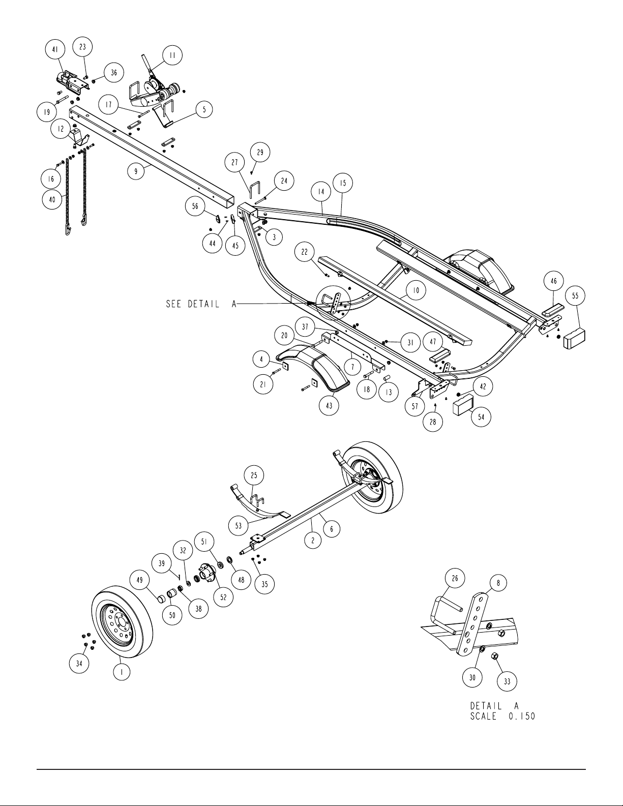
Remove the small parts from the frame by cutting the banding. Remove the bolt bag and sort all the nuts and bolts by size.
Tongue:
Take the tongue and slide into the tongue channel. Secure with
a 3/8” X 4” carriage bolt in the front and 3/8” X 3-7/16” X 4-1/8”
square u-bolt, 1” X 4-1/2” mounting strap and 3/8” flange lock nut in
the rear of the assembly. Thread the tongue wire harness through
the tongue and connect to the frame harness. Install grommets.
NOTE: Install the tongue in one of the two adjustment holes in the
tongue channel. Refer to the parts drawing for placement.
Safety Chain:
Insert a 3/8” X 1-1/4” hex bolt with a 3/8” flat washer and safety
chain through the lower hole on the front of the tongue. Secure with
a 3/8” flange lock nut. Repeat this procedure on the opposite side
of the tongue.
Coupler:
Mount the coupler onto the tongue with one (1) 1/2” X 4” hex bolt
and two (2) 1/2” X 1” hex bolts. Secure with 1/2” flange lock nuts.
Axle:
Install the spring bushing in the rear spring brackets with 1/2” X 31/4” hex bolts and 1/2” flange lock nuts. Position the axle under the
trailer with the spring eye to the front. Slip the flat end of the spring
in the rear spring bracket over the bushing and fasten the front
spring eye to the front of the spring bracket with 9/16” X 3-1/4” hex
bolts and 9/16” hex lock nuts.
Mount the tire and rim assemblies with 1/2” lug nuts and tighten to
80-90 ft./lbs. of torque.
Bunk:
Slide a 3/8” X 2-7/16” X 2-3/4” square bolt over the rear cross member with the threads facing the REAR. Place an adjustable bunk
bracket on the u-bolt legs and secure with 3/8” flange lock nuts.
Slide on a 3/8” X 2-7/16” X 2-3/4” square u-bolt over the front cross
member with the threads facing the FRONT. Place an adjustable
bunk bracket on the u-bolt legs and secure with 3/8” flange lock
nuts. Fasten the bunk assembly to the adjustable bunk brackets
just mounted and secure with 3/8” X 1” hex bolts and 3/8” flange
lock nuts.
Winch Post:
Attach the winch brace to the winch post assembly with a 3/8” X 4”
hex bolt in one (1) of the three (3) holes of adjustment. Position the
winch assembly on the tongue in the desired position and fasten
CAUTION:
To prevent damage to your water vehicle hull, place the water vehicle on the trailer, loosen bunk u-bolts so the bunks conform to the
hull. Tighten.
with a 3/8” X 3-7/16” X 4-1/8” square u-bolts, 1” X 4-1/2” mounting
straps and 3/8” flange lock nuts.
Tighten all fasteners before towing.
The law requires that the white wire on both the tongue and vehicle
wire harness be grounded to the trailer and towing vehicle.
Midwest Industries, Inc. Ida Grove, IA 51445 800.859.3028 www.shorelandr.com 0002990
Page 3 REV A 01/09/06
Page 4

Midwest Industries, Inc. Ida Grove, IA 51445 800.859.3028 www.shorelandr.com 0002990
Page 4 REV A 01/09/06
 Loading...