

Page 1
®
PWC1000
PWC1000 Single PWC TRailer - 1200 lb. - White
2 4300183 4.80X12-B Tire/MSilver Mod Rim
1 6249201 Frame Bundle - Single PWC
1 62340 Literature Bag - Trailers
PWCG1000 Single PWC TRailer - 1200 lb. - Galvanized
2 4300205 4.80X12-B Tire/Galv Mod Rim
1 6249200 Frame Bundle - Single PWC
1 62340 Literature Bag - Trailers
PWCBK1000 Single PWC TRailer - 1200 lb. - Black
2 4300183 4.80X12-B Tire/MSilver Mod Rim
1 6249203 Frame Bundle - Single PWC
1 62340 Literature Bag - Trailers
Midwest Industries, Inc. Ida Grove, IA 51445 800.859.3028 www.shorelandr.com 0003109
Tire Load Carrying
Size Range Capacity
4.80X12 B 780 lbs. per/tire
Refer to tire side wall for correct tire pressure.
Slide the water vehicle wither forward or backward on the
trailer until the proper tongue weight has been achieved.
Tire Size & Carrying Capacity Chart
Tongue Weight Adjustment
REV B 11/22/04
Page 2
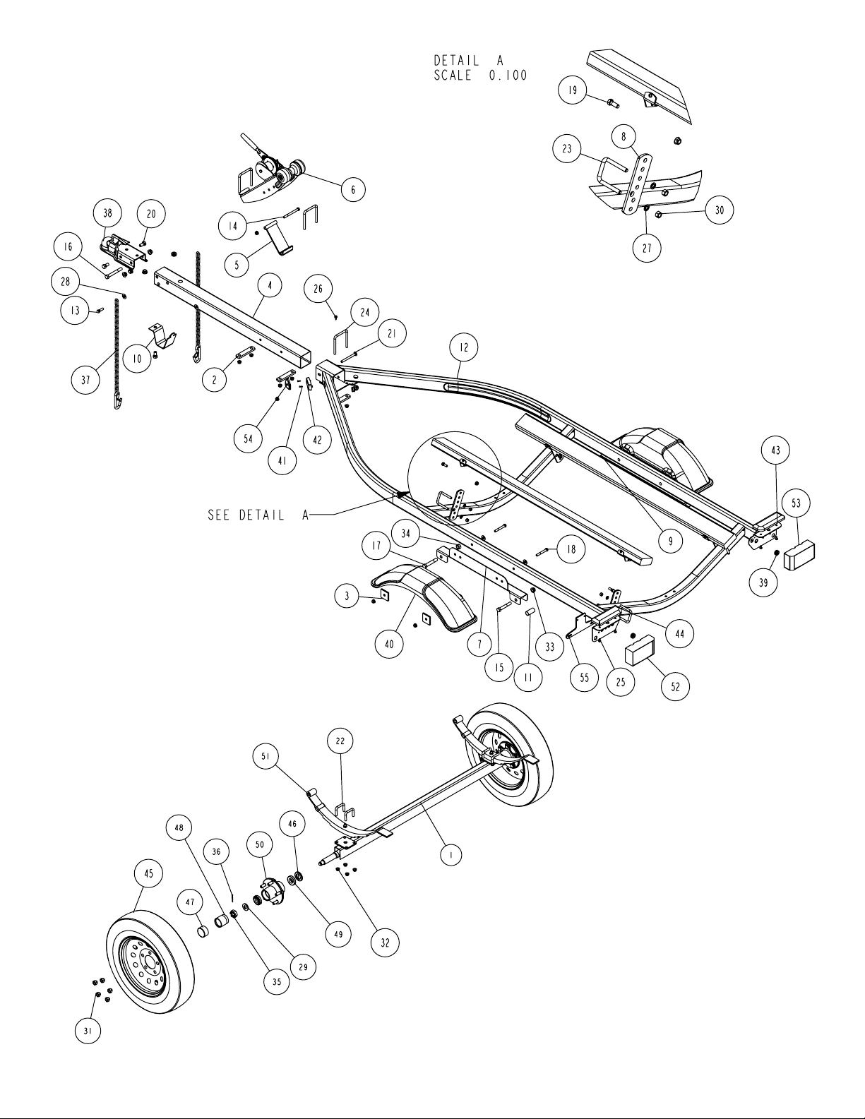
PARTS DRAWING
NOTE: Optional equipment and
replacement parts must be purchased
through an authorized ShoreLand’r
dealer.
Midwest Industries, Inc. Ida Grove, IA 51445 800.859.3028 www.shorelandr.com 0003109
REV B 11/22/04
Page 3

Material List for the PWC1000
NOTE: ShoreLand’r offerse their product line in either galvanized or painted finish. When ordering parts it is important that you specify the
finish or color you have on your product. The five digit number along with a two digit space _ _, notes the parts which can be purchased
with various finishes. When ordering these items use the five digit prefix and include the following two digit suffix for proper finish.
Suffix Finish / Color
00 or G Galvanized
01 Arctic White
03 or BK Black
Assemblies:
68064-- Winch Assembly
67381P 6’ Bunk Assembly
62491 Hardware Bag
62490-- Axle Assembly
Decals:
4810709 Trailer - Caution/Warning Decal ..............1
4850397 PWC Decal, Left .....................................1
4850398 PWC Decal, Right ...................................1
4811451 NMMA Certified Trailer Decal .................1
3110253 Latch Kit
SS818 1-1/16” - 1-1/16” Hub & Bearing Kit
BK-6 1-1/16” - 1-1/16” Bearing Kit
Midwest Industries, Inc. Ida Grove, IA 51445 800.859.3028 www.shorelandr.com 0003109
REV B 11/22/04
Page 4

Final Assembly Instructions
Remove all small parts from the frame by cutting the bands.
Remove the bolt bag and sort all nuts and bolts by size.
Tongue:
Remove the tongue assembly from the frame bundle and
slide into the tongue channel. Secure with a 3/8” X 4” carriage bolt in the front and 3/8” X 3-7/16” X 4-1/8” square
u-bolt, 1” X 4-1/2” mounting strap and 3/8” flange lock nut
in rear of the assembly. Thread the tongue wire harness
through the tongue and connect to the frame harness and
install the grommets. NOTE: Install the tongue in one of the
two adjustment holes in the tongue channel. Refer to the
parts drawing for placement.
Safety Chain:
Insert a 3/8” X 1-1/4” hex bolt with a 3/8” flat washer and
safety chain through the lower hole on the front of the tongue.
Secure with a 3/8” flat washer and 3/8” flange lock nut. Repeat this procedure on the opposite side of the tongue.
Coupler:
Mount the coupler onto the tongue with one (1) 1/2” X 4” hex
bolt and two (2) 1/2” X 1” hex bolts. Secure with 1/2” flange
lock nuts.
Winch Post:
Attach the winch brace to the winch post assembly with a
3/8” X 4” hex bolt in one (1) of the three (3) holes of adjustment. Position the winch assembly on the tongue in a
location that will best fit your watercraft. Fasten with 3/8” X
3-7/16” X 4-1/8” square u-bolt, 1” X 4-1/2” mounting straps
and 3/8” flange lock nuts.
Axle:
Install the spring bushing in the rear spring bracket with 1/2”
X 3-1/4” hex bolts and 1/2” flange lock nuts. Position the axle
under the trailer with the spring eye to the front. Slip the flat
end of the spring in the rear spring bracket and fasten the
front spring eye to the front of the spring bracket with 9/16” X
3-1/4” hex bolts and 9/16” hex lock nuts.
Mount the tire and rim assemblies with 1/2” lug nuts and
tighten to 80-90 ft./lbs. of torque.
Bunk:
Slide a 3/8” X 2-7/16” X 2-3/4” square bolt over the rear
cross member with the threads facing the FRONT. Place an
adjustable bunk bracket on the u-bolt legs and secure with
3/8” flange lock nuts. Slide a 3/8” X 2-7/16” X 2-3/4” square
u-bolt over the front cross member with the threads facing
the REAR. Place an adjustable bunk bracket on the u-bolt
legs and secure with 3/8” flange lock nuts. Fasten the bunk
assembly to the adjustable bunk brackets just mounted and
secure with 3/8” X 1” hex bolts and 3/8” flange lock nuts.
CAUTION:
To prevent damage to your water vehicle hull, place the wa-
ter vehicle on the trailer, loosen bunk u-bolts so the bunks
conform to the hull. Tighten.
To prevent damage to the trailer or tow vehicle, tighten all
fasteners before towing.
The law requires that the white wire on both the tongue and
tow vehicle wire harnesses be grounded to the trailer and
the towing vehicle.
Midwest Industries, Inc. Ida Grove, IA 51445 800.859.3028 www.shorelandr.com 0003109
REV B 11/22/04
 Loading...