

Page 1
®
PVB1412-03
Prairie View Pontoon Fishing Trailer
PVB1412-03 Prairie View Pontoon Fishing Trailer
62340 Literature Bag - Trailers
6606703 Frame Bundle - Pontoon Fishing
6578003 Tongue - 3x3x14 ga. x 7’
66066 Hardware Box - Pontoon Fishing
*4.80x12B Tire / T-Silver Mod Rim
*Check with your dealer/customer service representative for current tire/rim assembly part number.
ShoreLand’r offers its product line in painted nishes. When
ordering parts, it is important that you specify the nish or
color you have on your product. The 5-digit number along
with a 2-digit space _ _, note that the parts can be purchased
PVB1412-03 Specications
Capacity 1200 lbs.
GVWR: 1560 lbs.
GAWR: 1560 lbs.
Ship Wt: 335 lbs.
Frm Size: 1.5X3 (11 Ga)
Tire Size:
Rim Size: 12 X 4 “J”
Brake: N/A
Coupler: 2” Coupler
Suspension: 4 Leaf Slipper Springs
Tongue Size: 3X3X7’ Tongue
4.80x12B
in various nishes.
03..........Black
Midwest Industries, Inc. Ida Grove, IA 51445 800.859.3028 www.shorelandr.com 0003881
Rev A 06/14/2011
Page 1
Page 2
Midwest Industries, Inc. Ida Grove, IA 51445 800.859.3028 www.shorelandr.com 0003881
Rev A 06/14/2011
Page 2
Page 3

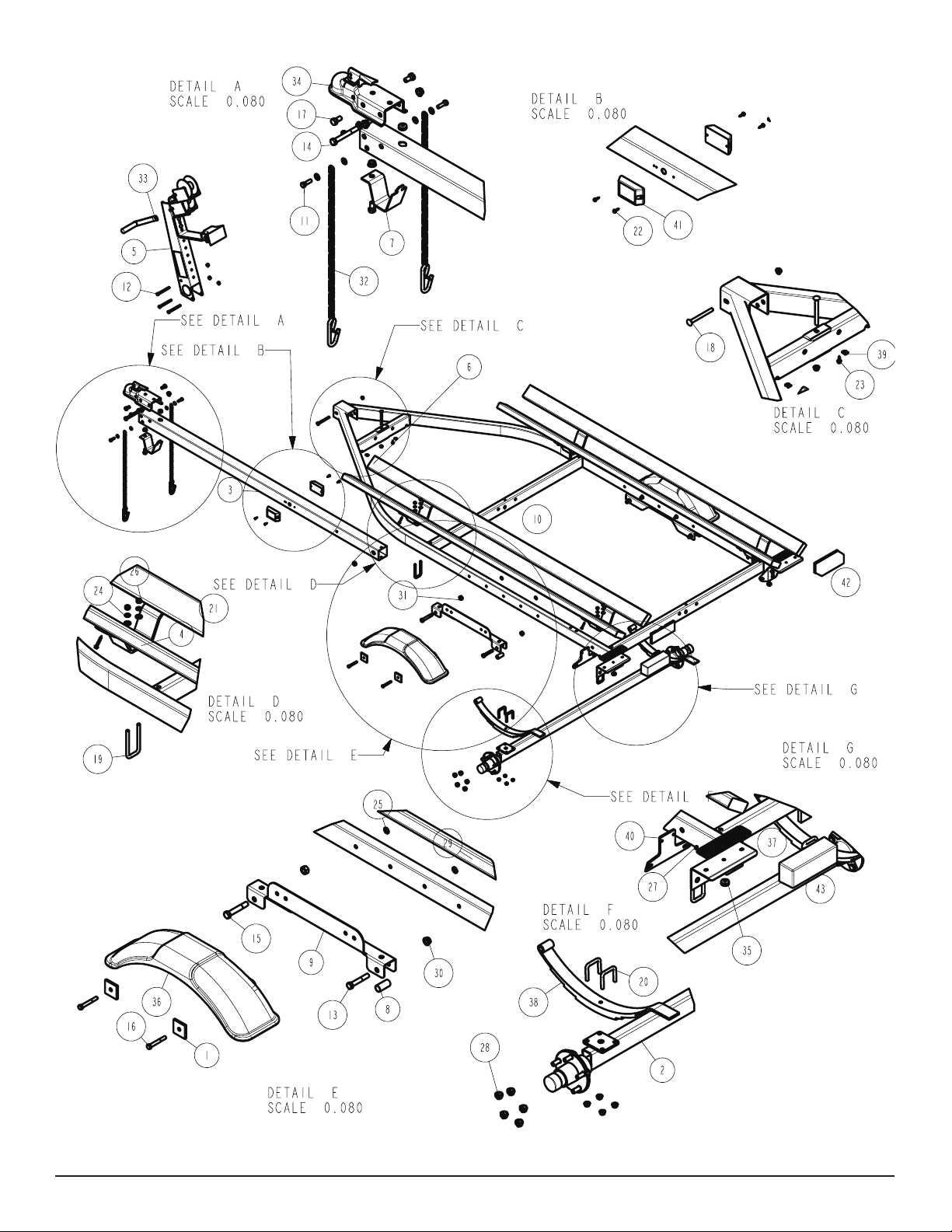
Side Marker Light
Locate the side marker light holes on the side of the tongue. Mount
the amber side marker light to the tongue using two #10 x 3/4” selfdrill screw. Refer to Detail B for placement. Repeat on other side
of tongue.
Safety Chain
Insert a 3/8” X 1-1/4” hex bolt through a 3/8” at washer, a safety
chain and another 3/8” at washer (in placement order). Proceed to
insert this assembly into the lower hole on the front of the tongue.
Secure with a 3/8” ange lock nut on the inside of the tongue tube.
Refer to Detail A for placement. Repeat on other side of tongue.
Coupler
Mount the coupler to the top two holes on the front of the tongue.
Using two 1/2” x 1” hex bolts in the rst two holes on the coupler/
tongue, secure with 1/2” ange lock nuts on the inside of the tongue
tube. The second hole on the tongue/coupler will be secured with
a 1/2” x 4” hex bolt and 1/2” ange lock nut on the inside of the
tongue tube. Refer to Detail A for placement.
Tongue Stand
Mount the tongue stand to the front under side of the tongue by
inserting the key lock into the key hole. Turn tongue stand and align
with front under side hole on the tongue. Place a 1/2” x 1” hex bolt
up through the tongue stand/tongue and secure with a 1/2” ange
lock nut on the inside of the tongue tube. Refer to Detail A for place-
ment.
FINAL ASSEMBLY INSTRUCTIONS
Remove all banded items and the hardware bag from the frame.
Remove the parts and sort by size.
Tongue
Locate the tongue and install by sliding it in the front of the tongue
channel, continue to rst crossmember as shown in Detail C. Insert
a 3/8” X 4” carriage bolt from the top down into the front crossmember and tongue. Secure with a 3/8” ange lock nut. Insert another
3/8” X 4” carriage bolt through the side of the tongue change cap on
the frame and into the tongue. Secure with a 3/8” lock nut.
Winch
Mount the winch stand to the tongue in location that would best t
your watercraft. Secure with three 3/8” x 4” hex bolts and three 3/8”
ange lock nuts.
Mount the winch handle on the winch assembly using the hardware
provided. Refer the parts drawing for placement.
Springs
Mount the leaf slipper springs to the top of the axle using two 3/8”
x 2-3/16” x 2” square u-bolts. Secure with 3/8” ange lock nuts. Repeat on opposite side of axle. Refer to Detail F for placement.
Axle
Place one spring bushing into the rear of the spring bracket and
secure with 1/2” x 3” hex bolt and 1/2” ange lock nut. Repeat on
opposite side of the trailer. Position the axle under the frame, slide
the slipper spring above the bushing. Raise the axle assembly up
so that the front of the spring line up with the front spring bracket
hole. Insert a 9/16” x 3-1/4” hex bolt and secure with a 9/16” hex
lock nut. Repeat on other side of the trailer. Refer to Detail E and
F. Do not overtighten. The springs must be able to react to road
variances.
Tire & Wheel Assemblies
Mount the tire and wheel assemblies using the 1/2” ne threaded
tapered lug nuts provided. Tighten to 85-95 ft/lb. of torque using the
rotation pattern as shown in the ShoreLandr ’s Owners Manual.
Re-torque the lug nuts after 50 miles of driving and then periodically thereafter.
Tire Size and Carrying Capacity Chart
Tire Size ............................
4.80 x 12B
GVWR ...............................1560 LB.
Carrying Capacity ..............1200 LB.
Axle....................................N/A
Refer to the tire side wall for correct tire pressure.
Midwest Industries, Inc. Ida Grove, IA 51445 800.859.3028 www.shorelandr.com 0003881
Rev A 06/14/2011
Page 3
Page 4

Midwest Industries, Inc. Ida Grove, IA 51445 800.859.3028 www.shorelandr.com 0003881
Rev A 06/14/2011
Page 4
Page 5

Midwest Industries, Inc. Ida Grove, IA 51445 800.859.3028 www.shorelandr.com 0003881
Rev A 06/14/2011
Page 5
Page 6

Bunk
Mount the saddle brackets to the frame using 3/8” x 1-15/16” x 4”
square u-bolts from the bottom side of the frame and up through
the saddle bracket. Secure with 3/8” at washers, 3/8” lock washers, and 3/8” hex nuts. Refer to Detail D for placement.
Mount the bunk to the saddle brackets on the frame using 1/4” x 11/2” self-tapping screws. About 4” of the bunk will protrude out the
back of the trailer, measuring from the taillight bracket.
Assembly should be complete except for tightening some of the
bolts. These bolts were left loose only to aid in adjusting the trailer
to the boat. All bolts and nuts must be tightened before towing!
NOTE: The law requires that the white ground wire on both the
tongue wire harness and vehicle harness must be properly grounded to the trailer and vehicle frames.
Midwest Industries, Inc. Ida Grove, IA 51445 800.859.3028 www.shorelandr.com 0003881
Rev A 06/14/2011
Page 6
 Loading...