

Page 1
®
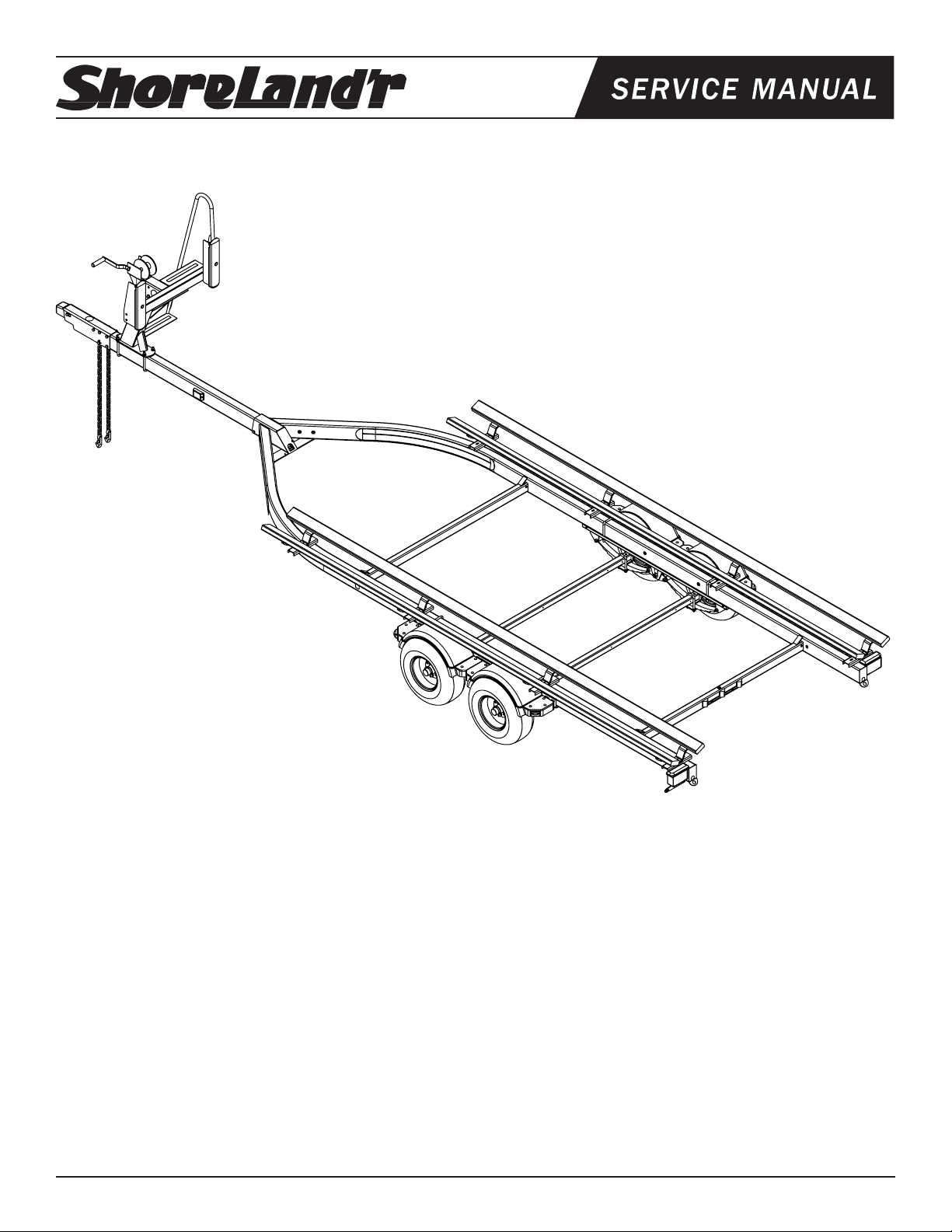
PT30TBBM
Bundles Required for PT30TBBM
69082 Literature Bag - Trailers - Brakes 1
Table of Contents: Page
80441-- Frame Bundle - PT30TBBM 1
*20.5x8x10E Tire / Galv. Rim 4
68028-- Tongue Assy w/UFP Actuator - Drum 1
60106-- Axle Assy w/Brakes - Pontoon 1
64157 Brake Kit - First Axle 1
*Check with your dealer/customer service representative for current tire/rim assembly part number.
Frame Drawing & Bill of Materials ............................... 2-3
Bunk Assembly Instructions ........................................ 3
Tongue / Side Marker Lights Assy Instr. ...................... 3
White Ground Wire Installation .................................... 3
Safety Chain Assembly Instructions ............................ 3
Brakeline Assembly Instructions .................................. 3
ShoreLand’r offers their product line in either galvanized or
painted finish. When ordering parts it is important that you
specify the finish or color you have on your product. The five
(5) digit number along with a two (2) digit space _ _, note the
parts which can be purchased with various finishes. When
ordering these items use the five (5) digit number along with
a two (2) digit suffix for the proper finish.
Tongue / Safety Chain Dwg/BOM ............................... 4
Winch PostDwg/BOM/Assy Instr. ................................ 5
Chassis Drawing & Bill of Materials ............................. 6-7
Spring Assembly Instructions ...................................... 8
First Axle Brake Instructions ........................................ 8
Second Axle Brake Instructions ................................... 8
Tire & Wheel Assembly ............................................... 8
Winch Post Adjustments .............................................. 9
00 ....... Galvanized
03 ....... Black
Midwest Industries, Inc. Ida Grove, IA 51445 800.859.3028 www.shorelandr.com 0003590
Page 1
Axle Adjustments ......................................................... 9
Safety Instructions ....................................................... 9
Page 2
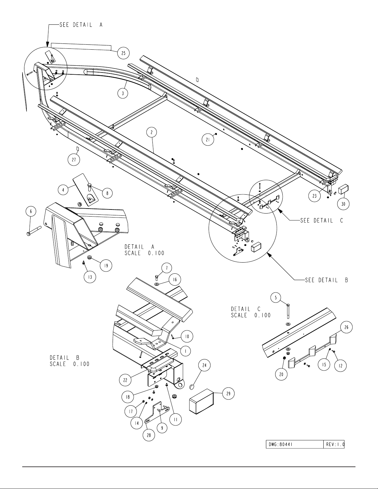
Diagram A
Midwest Industries, Inc. Ida Grove, IA 51445 800.859.3028 www.shorelandr.com 0003590
Page 2
Page 3

TONGUE
See Diagram B, Page 4.
Locate the proper length tongue. Insert the rear of the tongue into
the frame tongue channel until the mounting holes line up. Locate
the wire harness. Unwind and insert the end with the two plugs that
mate with the frame harness into the hole and route out the rear of
the tongue. Place a rubber grommet around the wire in the hole on
top of the tongue.
If brakes are going to be installed, the line should be installed inside
the tongue at this time.
SIDE MARKER LIGHTS FOR TONGUE
Note: When installing the tongue in the trailer, the side marker
lights will have to be mounted to the tongue. They are shipped in a
bag that is attached to the frame. Insert the wire harness from the
side marker light into the larger hole in the side of the tongue, then
route the wire harness to the rear of the tongue. Attach the light in
position using the No. 10 x ¾” self-tapping screws provided. Plug
the side marker light into one of the single plugs located at the rear
of the tongue harness. Repeat on the other side marker light.
Secure the tongue into the frame by placing a ½” x 4” cross bolt in
the front of the tongue channel. Locate the tongue cover plate as
shown in Diagram A, detail A. Feed the wire harness and brake line
if applicable through the hole in the tongue cover plate. Position the
tongue cover plate so the mounting hole aligns with the hole in the
rear bottom of the tongue. Place a ½” x 1 ½” hex bolt downward
through the tongue cover plate, tongue and tongue channel. Secure both mounting bolts with ½ flange lock nuts. Tighten.
Remove the small parts from the frame by cutting the banding. Remove the bolt bag and sort all the nuts and bolts by size.
BUNKS
Note that the bunk system is adjustable for width to fit most center dimensions of the pontoon tubes. Determine the centers of the
bunk support system that fits the pontoon tubes for the pontoon
that is going to be placed on the trailer and position accordingly.
Position the carpeted bunks so approximately 10” extends past
the back of the rear bunk saddle support. Attach the bunks to the
brackets using the ¼” x 1 ½” lag screws provided. Position the second bunk so it is just to the front of the rear bunk just installed.
Repeat this process on the bunks on the other side of the bunk
saddle support and then on the other side of the trailer.
Plug the tongue wire harness ends into the frame harnesses by
matching colors and ends. Push the excess wire provided either
into the rear of the tongue or else remove the grommet in the side
frame and place the excess wire in the side frame. Replace grommet just removed.
WHITE GROUND WIRE INSTALLATION
Place the self-tapping screw provided through the round metal ring
on the white ground wire of the tongue harness located at the rear
of the tongue. Attach the ground wire to the main frame by driving
the screw in the hole provided next to the tongue channel of the
frame. This will assure a positive ground for the lighting.
SAFETY CHAINS
Locate the 1/2” x 5” hex bolt. Slip the bolt through a 1/2” flat washer,
then place through the last link of one of the safety chains. Slide
through actuator housing and tongue. Slide other safety chain over
bolt and add a 1/2” flat washer. Secure with a 1/2” flange lock nut.
See Diagram B.
Assembly is complete.
BRAKE LINE
Locate the brass brake line coupling. Remove the plastic cap and
thread the brake line coming out the rear of the tongue into one
end of the coupling. Bend the line in a smooth gradual radius being
careful not to kink the line. Bend so it can be mated to the brake
line from the side frame. Once aligned, thread the side frame brake
line into the other end of the coupling. Tighten both lines into the
coupling.
Midwest Industries, Inc. Ida Grove, IA 51445 800.859.3028 www.shorelandr.com 0003590
Page 3
Page 4

Diagram B
Midwest Industries, Inc. Ida Grove, IA 51445 800.859.3028 www.shorelandr.com 0003590
Page 4
Page 5

Diagram C
WINCH POST
See Diagram C.
Position the winch post on the tongue and secure in place using
½” x 3 9/16” x 6” square U-bolts. Secure with ½” flange lock nuts.
Tighten only to hold in position because they will have to be moved
when the pontoon is placed on the trailer.
Attach the winch handle to the winch using the nylon locking nut
provided on the winch.
Midwest Industries, Inc. Ida Grove, IA 51445 800.859.3028 www.shorelandr.com 0003590
Page 5
Page 6

Diagram D
Midwest Industries, Inc. Ida Grove, IA 51445 800.859.3028 www.shorelandr.com 0003590
Page 6
Page 7

Midwest Industries, Inc. Ida Grove, IA 51445 800.859.3028 www.shorelandr.com 0003590
Page 7
Page 8

SPRINGS
See Diagram D.
Position the axle under the frame so it is properly orientated. All
2” x 2” pontoon axles have holes drilled for mounting brake lines.
These attaching holes must be positioned to the rear of the trailer.
(If a brake axle is being installed, make sure axle is oriented so the
brake backup plates are on the right sides of the trailer. (Right on
right and left of left.)
• Check all fittings and screws to make sure they are secure.
• Bleed the brake system according to brake manufacturer in-
structions.
Fill the actuator reservoir with brake fluid and bleed the line per the
bleeding instructions in one of the following; UFP Brake Bleeding
Manual or the ShoreLand’r Disc Brake Manual. Refill the reser-
voir and replace the reservoir cap.
Place the springs under the axle as shown so the closed eye of the
spring is to the front of the trailer. Drop two ½´x 2 9/16´x 5” square
U-bolts down around the axle and on each side of the spring as
shown.
Align the legs of the U-bolt with the holes in a spring pad and then
insert so the spring pad is up against the spring. Secure with ½”
flange lock nuts. Tighten to keep all items in position but do not securely tighten until the axle assembly is completely installed under
the frame.
AXLE
Place one of the spring bracket bushings into the rear of the spring
bracket and secure with a 9/16” x 3 1/4” hex bolt and hex lock nut.
Repeat in other spring bracket. Position the axle under the frame,
then hook the loop end of the spring around the bushings just installed. Note that if the axle is positioned too low when trying to
hook, the loops will not hook around the bushings.
Raise the front of the springs up so they align with the front hole
of the spring bracket. Secure in place with 9/16” X 3-1/4” hex bolts
and lock nuts. Repeat this process on the other spring.
Tighten all axle U-bolts and spring bolts not tightened at this time.
Note that the brake lines are not installed in or on these axles during assembly because of possible damage during shipping. The
side frame brake line is factory installed on all brake models.
• Remove all contents from the brake kit box and sort by size.
Locate and straighten the long brake line tubing.
• Begin forming the end of the long brake line tubing so it can be
inserted into the fitting on the left brake cluster. Carefully form
the tubing so once inserted into the fitting that it will run parallel
to the centerline of the axle and the back of the axle.
• Now place a clip over the line and insert a screw to hold in place
while attaching the one side of the tee to the long brake line tube
and tighten so it will lay flat against the axle tube with one open ing toward the top of the axle.
• Taking the 12” line begin forming this to fit into the fitting on the
right brake cluster, the line should be formed so that it will fit into
the other side of the tee attached to the long brake line.
• Take the remaining clips and screws and secure the line to the
rear of the axle placing the screws into the locations provided
making sure the brake line tubing fits into the loop on the clips.
• Screw the brake line hose into the opening on top of the tee and
tighten. Place the other end of the hose thru the clip on the
spring bracket and secure with the u-shaped clip.
• Uncoil only enough of the frame brake line to make it fit into the
end of the brake line hose.
SECOND AXLE PONTOON BRAKE LINE ASSEMBLY
Note that the brake lines are not installed in or on these axles dur-
ing assembly because of possible damage during shipping.
• Remove all contents from the brake kit box and sort by size.
Locate and straighten the long brake line tubing.
• Begin forming the end of the long brake line tubing so it can be
inserted into the fitting on the left brake cluster. Carefully form
the tubing so once inserted into the fitting that it will run parallel
to the centerline of the axle and the back of the axle.
• Now place a clip over the line and insert a screw to hold in
place while attaching the one side of the tee to the long brake
line tube and tighten so it will lay flat against the axle tube with
one opening toward the top of the axle.
• Taking the 12” line begin forming this to fit into the fitting on the
right brake cluster, the line should be formed so that it will fit
into the other side of the tee attached to the long brake line.
• Take the remaining clips and screws and secure the line to the
rear of the axle placing the screws into the locations provided
making sure the brake line tubing fits into the loop on the
clips.
• Take the brake line bracket and two (2) self tapping screws
and attach the bracket to the side frame of the trailer behind
the axle 2”.
• Screw the brake line hose into the opening on top of the
tee and tighten. Place the other end of the hose thru the clip
just mounted on the side frame and secure with the u-shaped
clip.
• Undo the frame brake line from the brake line hose and insert
the inverted flare fitting into the hose and reattach the frame
brake line.
• Uncoil the other brake line and fit it into the end of the brake
line hose and the other end into the fitting inserted on the other
hose and tighten.
• Check all fittings and screws to make sure they are secure.
• Bleed the brake system according to brake manufacturer in-
structions.
TIRE AND WHEEL ASSEMBLIES
Mount the tire and wheel assemblies using the ½” fine threaded
tapered lug nuts provided. Tighten to 85-95 ft/lb. of torque using the
rotation pattern as shown in the ShoreLandr’s Owners Manual.
Re-torque the lug nuts after 50 miles of driving and then periodi-
cally thereafter.
Midwest Industries, Inc. Ida Grove, IA 51445 800.859.3028 www.shorelandr.com 0003590
Page 8
Page 9

ADJUSTING INSTRUCTIONS
Place the pontoon on the trailer so that the pontoon tubes are flush
with the ends of the bunks. This will give you maximum support.
The bunk spacing has already been determined and set for width
when the trailer was assembled.
WINCH POST
With the pontoon in its proper position, slide the winch post assembly backward until it contacts the deck. The plastic stops allow
for the variance in most deck heights. It is adjustable up or down
approximately 3” if required. This is accomplished by loosening and
removing the two bolts that attach the top of the winch post assembly to the base.
Once the winch post is contacting the deck, tighten in position.
Hook the winch strap into the bow eye and tighten by cranking the
winch.
AXLE ADJUSTMENT
The amount of tongue weight on your trailer can be adjusted as
follows:
To lower the tongue weight, adjust the axle assembly forward. To
increase the tongue weight, adjust the axle assembly backward.
The distance that the axle assembly has to be moved will vary because it is directly related to the weight and center of gravity of the
boat placed on it.
Best towing is achieved when the tongue weight is 5-7% of the total
gross load of the complete unit.
Note: The law requires that the white ground wire on both the
tongue wire harness and vehicle harness be properly grounded to
respective trailer and vehicle frames.
Recheck all fasteners on the complete trailer to make sure they are
all tight and ready for towing. All fasteners should be periodically
checked before towing.
See your ShoreLand’r Owner’s Guide for further technical information regarding your trailer and its components.
Midwest Industries, Inc. Ida Grove, IA 51445 800.859.3028 www.shorelandr.com 0003590
Page 9
Page 10

Midwest Industries, Inc. Ida Grove, IA 51445 800.859.3028 www.shorelandr.com 0003590
Page 10
 Loading...